1993 DODGE TRUCK boot
[x] Cancel search: bootPage 42 of 1502
•
LUBRICATION
AND
MAINTENANCE
0 - 23 GEAR SHIFTER BOOTS
Inspect the shifter boots periodically for stone and
heat damage. Replace, if necessary.
SEVERE DRIVING CONDITIONS The interval between the transmission drain and
refill maintenance should be decreased to:
• NV4500 manual transmission—every 29 000 km (18,000 miles)
• Automatic transmission—every 19 000 km (12,000
miles)
A severe driving condition includes:
• Extended operation with heavy cargo loads
• Driving in deep mud or snow
• Off-road operation (4WD)
• Trailer towing
• Operation as a commercial vehicle
• Snow plowing
MANUAL TRANSMISSIONS
INSPECTION/LUBE
OIL
LEVEL
The transmission should be checked for leaks when
other service is necessary under the vehicle. To check
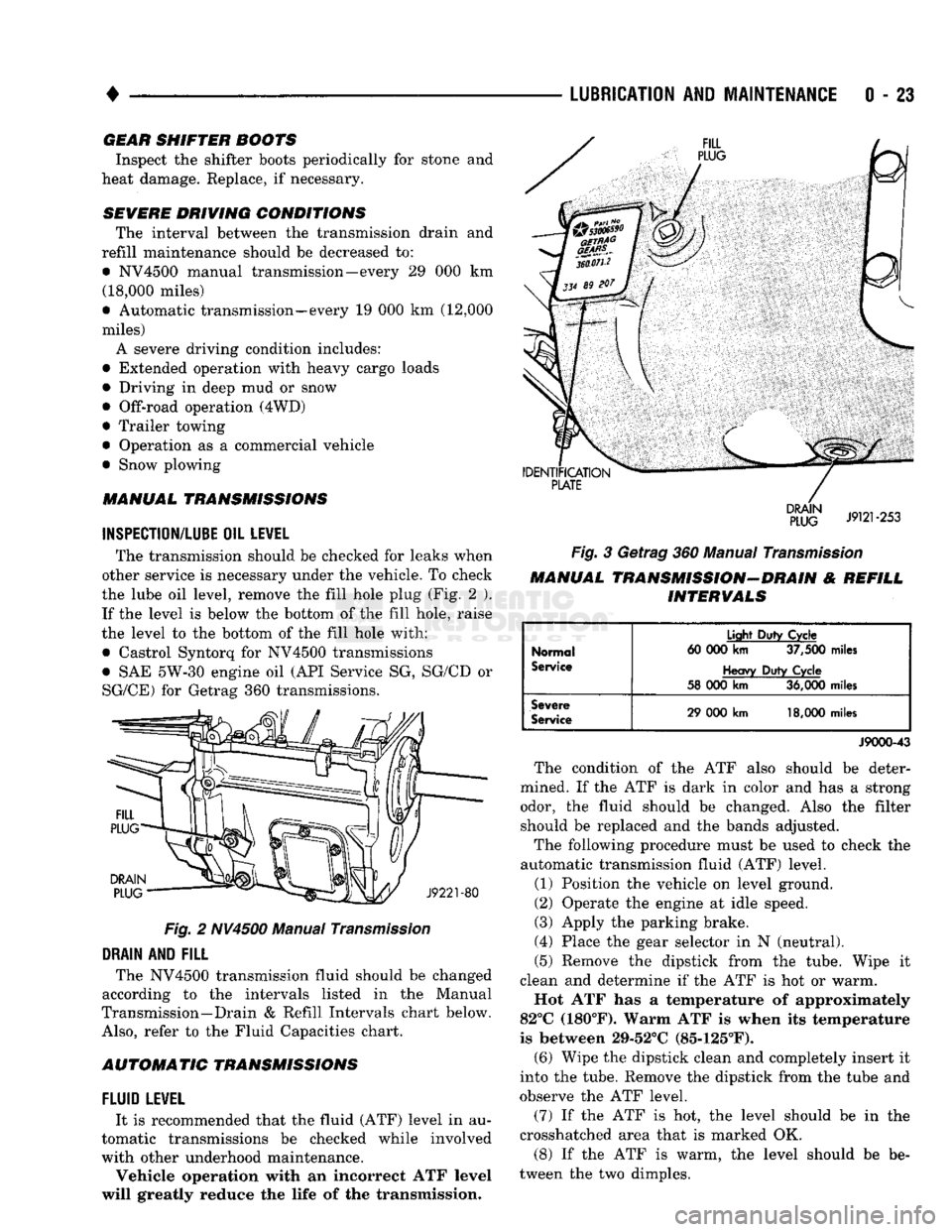
the lube oil level, remove the fill hole plug (Fig. 2 ). If the level is below the bottom of the fill hole, raise
the level to the bottom of the fill hole with:
• Castrol Syntorq for NV4500 transmissions
• SAE 5W-30 engine oil (API Service SG, SG/CD or
SG/CE) for Getrag 360 transmissions.
Fig.
2 NV4500 Manual
Transmission
DRAIN
AND
FILL
The NV4500 transmission fluid should be changed
according to the intervals listed in the Manual
Transmission—Drain & Refill Intervals chart below.
Also,
refer to the Fluid Capacities chart.
AUTOMATIC TRANSMISSIONS
FLUID
LEWEL
It is recommended that the fluid (ATF) level in au
tomatic transmissions be checked while involved
with other underhood maintenance.
Vehicle operation with an incorrect ATF level
will greatly reduce the life of the transmission.
Fig.
3 Getrag 360 Manual
Transmission
MANUAL TRANSMISSION-DRAIN & REFILL INTERVALS
Normal
Service
Light
Duty
Cycle
60 000
km
37,500
miles
Heavy
Duty
Cycle
58 000
km
36,000
miles
Severe
Service
29 000
km
18,000
miles
J9000-43
The condition of the ATF also should be deter
mined. If the ATF is dark in color and has a strong odor, the fluid should be changed. Also the filter should be replaced and the bands adjusted.
The following procedure must be used to check the
automatic transmission fluid (ATF) level.
(1) Position the vehicle on level ground.
(2) Operate the engine at idle speed.
(3) Apply the parking brake.
(4) Place the gear selector in N (neutral).
(5) Remove the dipstick from the tube. Wipe it
clean and determine if the ATF is hot or warm.
Hot ATF has a temperature of approximately
82°C (180°F). Warm ATF is when its temperature
is between 29-52°C (85-125°F). (6) Wipe the dipstick clean and completely insert it
into the tube. Remove the dipstick from the tube and
observe the ATF level.
(7) If the ATF is hot, the level should be in the
crosshatched area that is marked OK.
(8) If the ATF is warm, the level should be be
tween the two dimples.
Page 50 of 1502
•
LUBRICATION
AND
MAINTENANCE
0 - 31
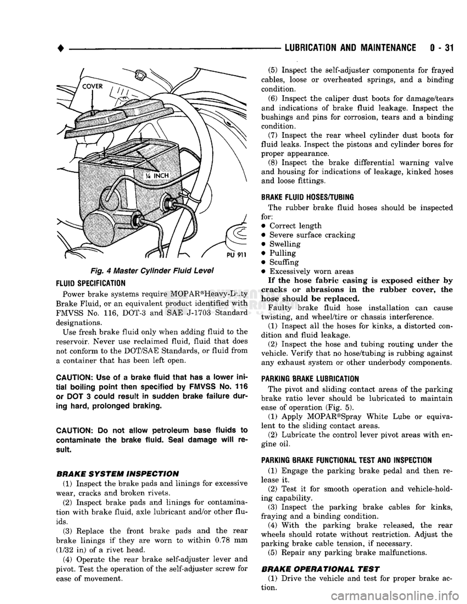
Fig. 4 Master Cylinder Fluid Level
FLUID
SPECIFICATION
Power brake systems require MOP AR®Heavy-D uty
Brake Fluid, or an equivalent product identified with
FMVSS No. 116, DOT-3 and SAE J-1703 Standard designations. Use fresh brake fluid only when adding fluid to the
reservoir. Never use reclaimed fluid, fluid that does not conform to the DOT/SAE Standards, or fluid from a container that has been left open.
CAUTION:
Use of a
brake fluid that
has a
lower ini
tial
boiling point then specified
by
FMVSS
No. 116
or
DOT 3
could result
in
sudden brake failure dur
ing
hard, prolonged braking.
CAUTION:
Do not
allow petroleum base
fluids
to
contaminate
the
brake fluid. Seal damage
will
re
sult.
BRAKE SYSTEM INSPECTION (1) Inspect the brake pads and linings for excessive
wear, cracks and broken rivets.
(2) Inspect brake pads and linings for contamina
tion with brake fluid, axle lubricant and/or other flu
ids.
(3) Replace the front brake pads and the rear
brake linings if they are worn to within 0.78 mm (1/32 in) of a rivet head.
(4) Operate the rear brake self-adjuster lever and
pivot. Test the operation of the self-adjuster screw for ease of movement. (5) Inspect the self-adjuster components for frayed
cables, loose or overheated springs, and a binding
condition.
(6) Inspect the caliper dust boots for damage/tears
and indications of brake fluid leakage. Inspect the
bushings and pins for corrosion, tears and a binding condition.
(7) Inspect the rear wheel cylinder dust boots for
fluid leaks. Inspect the pistons and cylinder bores for
proper appearance. (8) Inspect the brake differential warning valve
and housing for indications of leakage, kinked hoses and loose fittings.
BRAKE
FLUID
HOSES/TUBING
The rubber brake fluid hoses should be inspected
for:
• Correct length
• Severe surface cracking
• Swelling
• Pulling
• Scuffing
• Excessively worn areas If the hose fabric casing is exposed either by
cracks or abrasions in the rubber cover, the
hose should be replaced.
Faulty brake fluid hose installation can cause
twisting, and wheel/tire or chassis interference.
(1) Inspect all the hoses for kinks, a distorted con
dition and fluid leakage. (2) Inspect the hose and tubing routing under the
vehicle. Verify that no hose/tubing is rubbing against any exhaust system or other underbody components.
PARKING
BRAKE
LUBRICATION
The pivot and sliding contact areas of the parking
brake ratio lever should be lubricated to maintain ease of operation (Fig. 5).
(1) Apply MOPAR®Spray White Lube or equiva
lent to the sliding contact areas.
(2) Lubricate the control lever pivot areas with en
gine oil.
PARKING
BRAKE
FUNCTIONAL
TEST
AND
INSPECTION
(1) Engage the parking brake pedal and then re
lease it. (2) Test it for smooth operation and vehicle-hold
ing capability.
(3) Inspect the parking brake cables for kinks,
fraying and a binding condition. (4) With the parking brake released, the rear
wheels should rotate without restriction. Adjust the
parking brake cable tension, if necessary.
(5) Repair any parking brake malfunctions.
BRAKE OPERATIONAL TEST (1) Drive the vehicle and test for proper brake ac
tion.
Page 78 of 1502
•
FRONT
SUSPENSION
AND
AXLE
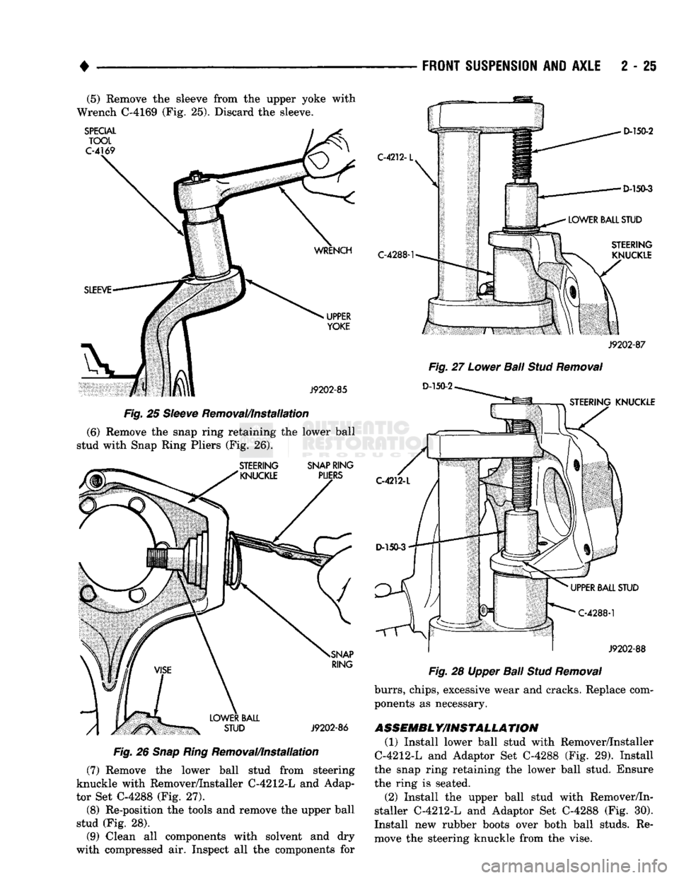
2 - 25 (5) Remove the sleeve from the upper yoke with
Wrench C-4169 (Fig. 25). Discard the sleeve.
Fig.
25
Sleeve
Removal/Installation
(6) Remove the snap ring retaining the lower ball
stud with Snap Ring Pliers (Fig. 26).
Fig.
26
Snap
Ring
Removal/Installation
(7) Remove the lower ball stud from steering
knuckle with Remover/Installer C-4212-L and Adap
tor Set C-4288 (Fig. 27).
(8) Re-position the tools and remove the upper ball
stud (Fig. 28).
(9) Clean all components with solvent and dry
with compressed air. Inspect all the components for
Fig.
28 Upper
Ball
Stud
Removal
burrs,
chips, excessive wear and cracks. Replace com
ponents as necessary.
ASSEMBL Y/INSTALLA TION
(1) Install lower ball stud with Remover/Installer
C-4212-L and Adaptor Set C-4288 (Fig. 29). Install
the snap ring retaining the lower ball stud. Ensure
the ring is seated.
(2) Install the upper ball stud with Remover/In
staller C-4212-L and Adaptor Set C-4288 (Fig. 30).
Install new rubber boots over both ball studs. Re
move the steering knuckle from the vise.
Page 214 of 1502
•
BRAKES
5 - 27 CHRYSLER
DISC
BRAKE
INDEX
page
Caliper
Installation
. 33
Caliper Overhaul
32
Caliper Removal
31
Disc
Brake Inspection
29
Disc
Brakeshoe
Installation
, 31
GENERAL
INFORMATION
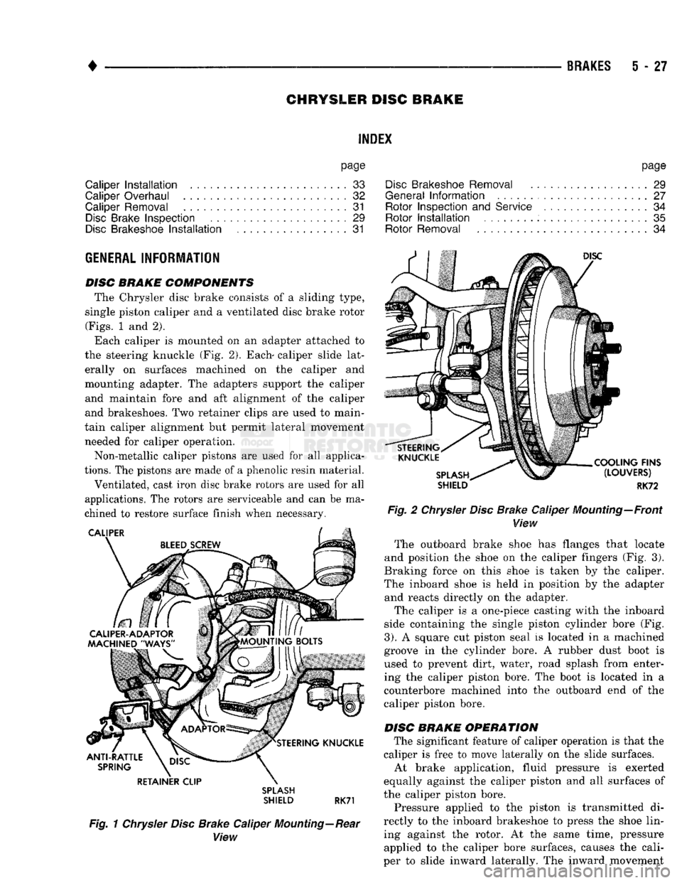
DISC BRAKE COMPONENTS The Chrysler disc brake consists of a sliding type,
single piston caliper and a ventilated disc brake rotor
(Figs.
1 and 2).
Each caliper is mounted on an adapter attached to
the steering knuckle (Fig. 2). Each- caliper slide lat erally on surfaces machined on the caliper and
mounting adapter. The adapters support the caliper and maintain fore and aft alignment of the caliper
and brakeshoes. Two retainer clips are used to main
tain caliper alignment but permit lateral movement needed for caliper operation.
Non-metallic caliper pistons are used for all applica
tions.
The pistons are made of a phenolic resin material.
Ventilated, cast iron disc brake rotors are used for all
applications. The rotors are serviceable and can be ma
chined to restore surface finish when necessary. RETAINER CLIP
SPLASH
SHIELD RK71
Fig. 1 Chrysler Disc Brake Caliper Mounting—Rear View
page
Disc
Brakeshoe Removal
29
General
Information
....................... 27
Rotor Inspection
and
Service
................ 34
Rotor
Installation
. 35
Rotor Removal
34
SHIELD
RK72
Fig. 2 Chrysler Disc Brake Caliper Mounting—Front View The outboard brake shoe has flanges that locate
and position the shoe on the caliper fingers (Fig. 3).
Braking force on this shoe is taken by the caliper.
The inboard shoe is held in position by the adapter and reacts directly on the adapter.
The caliper is a one-piece casting with the inboard
side containing the single piston cylinder bore (Fig.
3).
A square cut piston seal is located in a machined
groove in the cylinder bore. A rubber dust boot is used to prevent dirt, water, road splash from enter
ing the caliper piston bore. The boot is located in a
counterbore machined into the outboard end of the
caliper piston bore.
DISC BRAKE OPERATION The significant feature of caliper operation is that the
caliper is free to move laterally on the slide surfaces. At brake application, fluid pressure is exerted
equally against the caliper piston and all surfaces of
the caliper piston bore.
Pressure applied to the piston is transmitted di
rectly to the inboard brakeshoe to press the shoe lin ing against the rotor. At the same time, pressure applied to the caliper bore surfaces, causes the cali
per to slide inward laterally. The inward movement
Page 216 of 1502
•
BRAKES
5 - 29 presses the outboard shoe lining against the opposite
side of the rotor to complete braking action.
The application or release of fluid pressure causes
only a very slight movement of the caliper and pis
ton. At brake release, the piston and caliper return
to the non-applied position.
The brakeshoes do not retract an appreciable dis
tance from the rotor. The minimal running clearance
between the lining and rotor provides improved re sponse and reduced pedal travel. It also helps in pre
venting dirt and foreign material from lodging
between the shoe and rotor surfaces.
DISC
BRAKE
LINING WEAR COMPENSATION
Normal lining wear is compensated for by extension
of the caliper piston and by lateral movement of the cal
iper in the adapter. Piston position is also determined
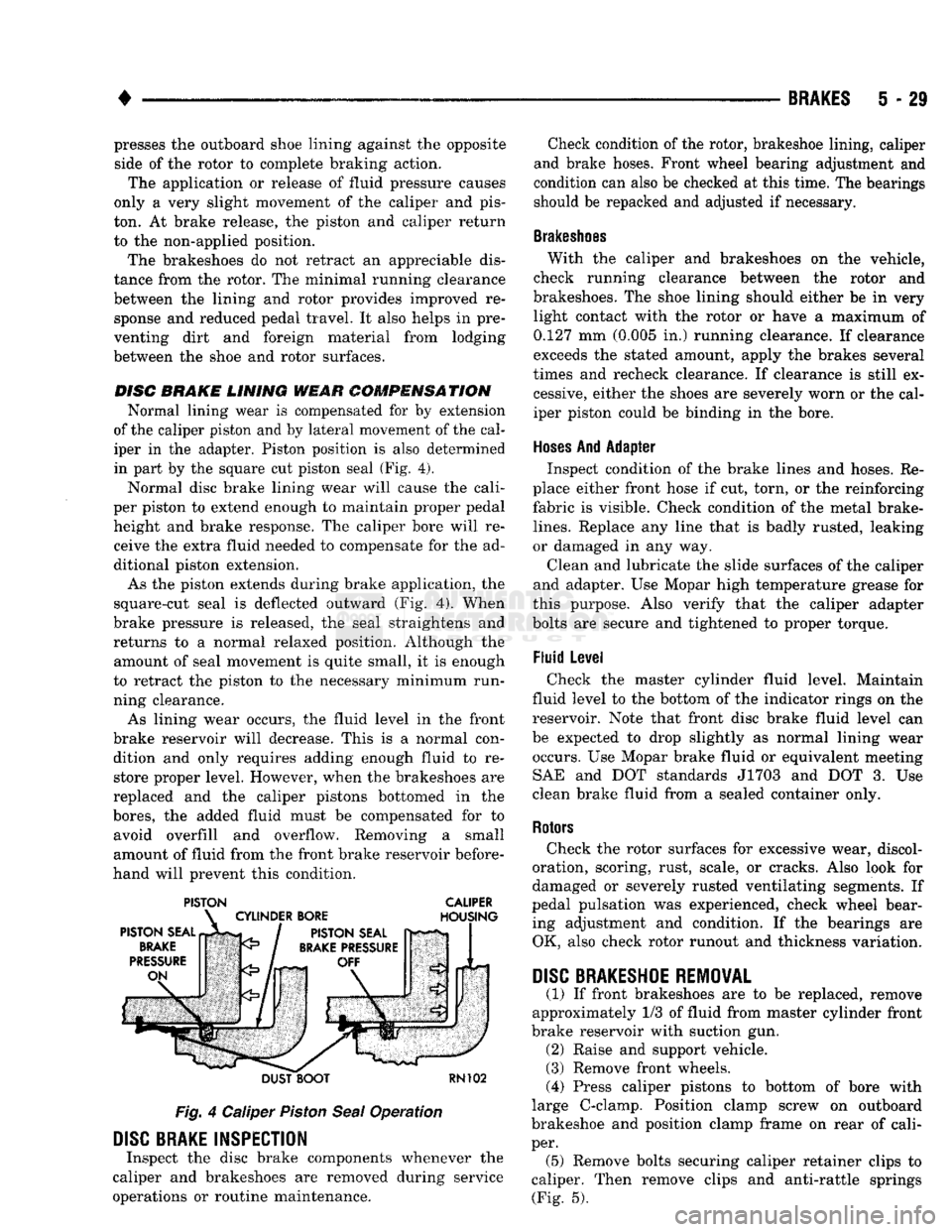
in part by the square cut piston seal (Fig. 4).
Normal disc brake lining wear will cause the cali
per piston to extend enough to maintain proper pedal height and brake response. The caliper bore will receive the extra fluid needed to compensate for the ad
ditional piston extension.
As the piston extends during brake application, the
square-cut seal is deflected outward (Fig. 4). When
brake pressure is released, the seal straightens and
returns to a normal relaxed position. Although the amount of seal movement is quite small, it is enough
to retract the piston to the necessary minimum run
ning clearance.
As lining wear occurs, the fluid level in the front
brake reservoir will decrease. This is a normal con dition and only requires adding enough fluid to restore proper level. However, when the brakeshoes are
replaced and the caliper pistons bottomed in the
bores,
the added fluid must be compensated for to avoid overfill and overflow. Removing a small
amount of fluid from the front brake reservoir before
hand will prevent this condition.
PISTON CALIPER
DUST BOOT
RN102
Fig.
4 Caliper
Piston
Seal
Operation
DISC
BRAKE INSPECTION
Inspect the disc brake components whenever the
caliper and brakeshoes are removed during service
operations or routine maintenance. Check condition of the rotor, brakeshoe lining, caliper
and brake hoses. Front wheel bearing adjustment and
condition can also be checked at this time. The bearings
should be repacked and adjusted if necessary.
Brakeshoes
With the caliper and brakeshoes on the vehicle,
check running clearance between the rotor and
brakeshoes. The shoe lining should either be in very light contact with the rotor or have a maximum of
0.127 mm (0.005 in.) running clearance. If clearance
exceeds the stated amount, apply the brakes several
times and recheck clearance. If clearance is still ex cessive, either the shoes are severely worn or the cal
iper piston could be binding in the bore.
Hoses
And Adapter Inspect condition of the brake lines and hoses. Re
place either front hose if cut, torn, or the reinforcing
fabric is visible. Check condition of the metal brake-
lines.
Replace any line that is badly rusted, leaking
or damaged in any way.
Clean and lubricate the slide surfaces of the caliper
and adapter. Use Mopar high temperature grease for
this purpose. Also verify that the caliper adapter
bolts are secure and tightened to proper torque.
Fluid Level Check the master cylinder fluid level. Maintain
fluid level to the bottom of the indicator rings on the
reservoir. Note that front disc brake fluid level can
be expected to drop slightly as normal lining wear occurs. Use Mopar brake fluid or equivalent meeting SAE and DOT standards J1703 and DOT 3. Use
clean brake fluid from a sealed container only.
Rotors
Check the rotor surfaces for excessive wear, discol
oration, scoring, rust, scale, or cracks. Also look for
damaged or severely rusted ventilating segments. If
pedal pulsation was experienced, check wheel bear ing adjustment and condition. If the bearings are OK, also check rotor runout and thickness variation.
DISC
BRAKESHOE
REMOVAL
(1) If front brakeshoes are to be replaced, remove
approximately 1/3 of fluid from master cylinder front
brake reservoir with suction gun. (2) Raise and support vehicle.
(3) Remove front wheels.
(4) Press caliper pistons to bottom of bore with
large C-clamp. Position clamp screw on outboard
brakeshoe and position clamp frame on rear of cali
per. (5) Remove bolts securing caliper retainer clips to
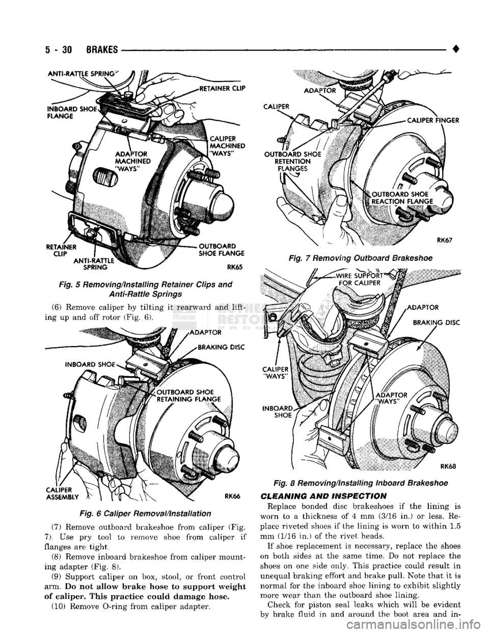
caliper. Then remove clips and anti-rattle springs (Fig. 5).
Page 217 of 1502
5 - 31
BRAKES
Fig.
5 Removing/installing Retainer Clips and Anti-Rattle Springs (6) Remove caliper by tilting it rearward and lift
ing up and off rotor (Fig. 6).
Fig.
6 Caliper Removal/Installation
(7) Remove outboard brakeshoe from caliper (Fig.
7).
Use pry tool to remove shoe from caliper if
flanges are tight,
(8) Remove inboard brakeshoe from caliper mount
ing adapter (Fig. 8). (9) Support caliper on box, stool, or front control
arm. Do not allow brake hose to support weight
of caliper. This practice could damage hose.
(10) Remove O-ring from caliper adapter. •
Fig.
7
Removing
Outboard
Brakeshoe
Fig.
8 Removing/Installing Inboard
Brakeshoe
CLEANING
AND
INSPECTION
Replace bonded disc brakeshoes if the lining is
worn to a thickness of 4 mm (3/16 in.) or less. Re
place riveted shoes if the lining is worn to within 1.5
mm (1/16 in.) of the rivet heads.
If shoe replacement is necessary, replace the shoes
on both sides at the same time. Do not replace the shoes on one side only. This practice could result in
unequal braking effort and brake pull. Note that it is
normal for the inboard shoe lining to exhibit slightly more wear than the outboard shoe lining. Check for piston seal leaks which will be evident
by brake fluid in and around the boot area and in-
Page 218 of 1502
•
BRAKES
5 - 31 board lining. Also check condition of the caliper pis
ton dust boot. If leakage is evident or if the boot is
cut, torn, or damaged in any way, it will be necessary to overhaul the caliper.
Remove the O-ring from the caliper adapter and clean
the slide surfaces of the adapter and the machined ways on the caliper with a wire brush and sandpaper.
DISC
BRAKESHOE
INSTALLATION
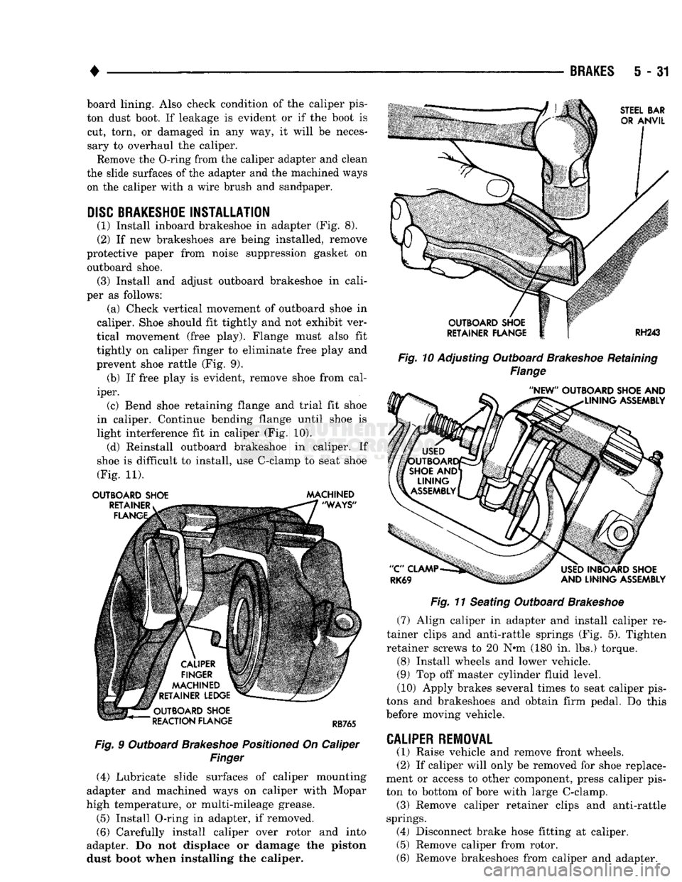
(1) Install inboard brakeshoe in adapter (Fig. 8).
(2) If new brakeshoes are being installed, remove
protective paper from noise suppression gasket on outboard shoe. (3) Install and adjust outboard brakeshoe in cali
per as follows: (a) Check vertical movement of outboard shoe in
caliper. Shoe should fit tightly and not exhibit ver
tical movement (free play). Flange must also fit
tightly on caliper finger to eliminate free play and
prevent shoe rattle (Fig. 9). (b) If free play is evident, remove shoe from cal
iper. (c) Bend shoe retaining flange and trial fit shoe
in caliper. Continue bending flange until shoe is
light interference fit in caliper (Fig. 10). (d) Reinstall outboard brakeshoe in caliper. If
shoe is difficult to install, use C-clamp to seat shoe
(Fig. 11).
OUTBOARD SHOE MACHINED
Fig.
9 Outboard
Brakeshoe
Positioned
On Caliper
Finger
(4) Lubricate slide surfaces of caliper mounting
adapter and machined ways on caliper with Mopar
high temperature, or multi-mileage grease.
(5) Install O-ring in adapter, if removed.
(6) Carefully install caliper over rotor and into
adapter. Do not displace or damage the piston dust boot when installing the caliper.
Fig. 10
Adjusting Outboard
Brakeshoe
Retaining
Flange
Fig.
11 Seating Outboard
Brakeshoe
(7) Align caliper in adapter and install caliper re
tainer clips and anti-rattle springs (Fig. 5). Tighten
retainer screws to 20 N«m (180 in. lbs.) torque.
(8) Install wheels and lower vehicle.
(9) Top off master cylinder fluid level. (10) Apply brakes several times to seat caliper pis
tons and brakeshoes and obtain firm pedal. Do this
before moving vehicle.
CALIPER
REMOVAL
(1) Raise vehicle and remove front wheels.
(2) If caliper will only be removed for shoe replace
ment or access to other component, press caliper pis
ton to bottom of bore with large C-clamp. (3) Remove caliper retainer clips and anti-rattle
springs. (4) Disconnect brake hose fitting at caliper. (5) Remove caliper from rotor.
(6) Remove brakeshoes from caliper and adapter.
Page 219 of 1502
5
- 32
BRAKES
•
CALIPER
OVERHAUL
CALIPER DISASSEMBLY (1) Drain
old
fluid
out of
caliper.
(2)
Pad
outboard shoe side
of
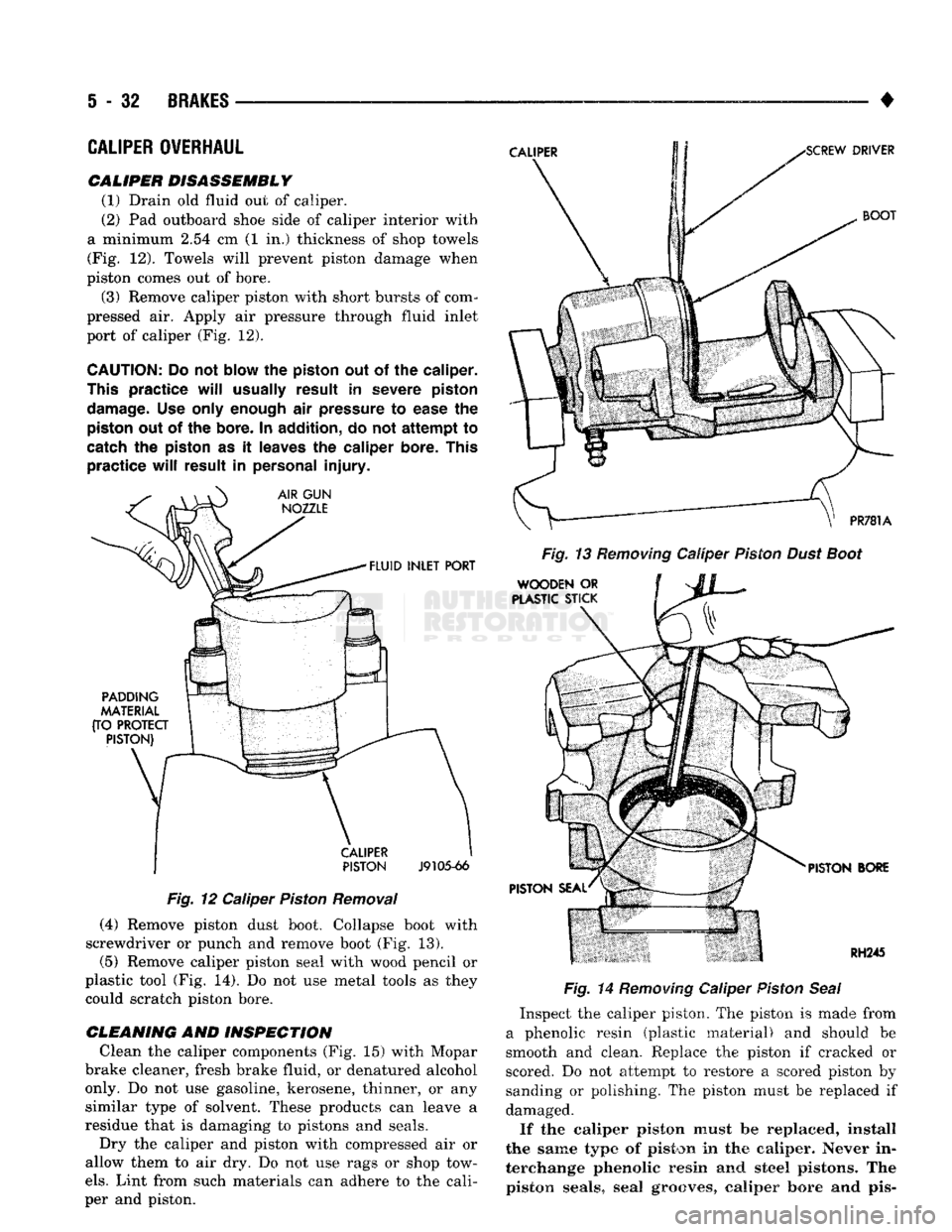
caliper interior with
a minimum
2.54 cm (1 in.)
thickness
of
shop towels (Fig.
12).
Towels will prevent piston damage when
piston comes
out of
bore.
(3) Remove caliper piston with short bursts
of
com
pressed
air.
Apply
air
pressure through fluid inlet
port
of
caliper
(Fig. 12).
CAUTION:
Do
not
blow
the
piston
out of the
caliper.
This
practice
will
usually
result
in
severe piston
damage.
Use
only enough
air
pressure
to
ease
the
piston
out of the
bore.
In
addition,
do not
attempt
to
catch
the
piston
as it
leaves
the
caliper
bore. This
practice
will
result
in
personal
injury.
Fig.
12
Caliper Piston Removal
(4) Remove piston dust boot. Collapse boot with
screwdriver
or
punch
and
remove boot
(Fig. 13).
(5) Remove caliper piston seal with wood pencil
or
plastic tool
(Fig. 14). Do not use
metal tools
as
they could scratch piston bore.
CLEANING
AND
INSPECTION Clean
the
caliper components
(Fig. 15)
with Mopar
brake cleaner, fresh brake fluid,
or
denatured alcohol only.
Do not use
gasoline, kerosene, thinner,
or any
similar type
of
solvent. These products
can
leave
a
residue that
is
damaging
to
pistons
and
seals. Dry
the
caliper
and
piston with compressed
air or
allow them
to air dry. Do not use
rags
or
shop tow
els.
Lint from such materials
can
adhere
to the
cali
per
and
piston. Fig. 14 Removing Caliper Piston Seal
Inspect
the
caliper piston.
The
piston
is
made from
a phenolic resin (plastic material)
and
should
be
smooth
and
clean. Replace
the
piston
if
cracked
or
scored.
Do not
attempt
to
restore
a
scored piston
by
sanding
or
polishing.
The
piston must
be
replaced
if
damaged.
If
the
caliper piston must
be
replaced, install
the same
type
of
piston
in the
caliper.
Never
in
terchange phenolic resin
and
steel
pistons.
The
piston seals,
seal
grooves,
caliper bore
and pis-