1993 DODGE TRUCK fuel filter location
[x] Cancel search: fuel filter locationPage 34 of 1502

•
LUBRICATION
AND
MAINTENANCE
0 - 15
DIESEL
ENGINES
The Diesel engine oil level indicator is located at
the left center of the engine, above the
fuel
injection
pump (Fig. 3).
Fig.
3
Diesel
Engine
Oil
Dipstick
ACCEPTABLE
OIL
LEVEL
To maintain proper lubrication of an engine, the
engine oil must be maintained at an acceptable level.
For gasoline engines, the acceptable levels are indi cated between the ADD and
FULL
marks on oil
dip
stick. For Diesel engines, the acceptable levels are
indicated between the L (low) and H
(high) marks
on
oil dipstick. The oil level should be checked periodically. The
vehicle should be on a level surface. Wait for
five
minutes after stopping the engine. For gasoline en
gines,
add oil only when the level indicated on the
dipstick is at or below the ADD mark. For Diesel en
gines,
add oil only when the level indicated on the
dipstick is between the L and H marks.
Never oper
ate a Diesel
engine when
the oil
level
is below
the L mark. The distance between the L and H
marks represents 1.9L (2 Qts) engine oil.
CAUTION:
Do not
overfill
an
engine crankcase
with
oil. This
will
cause
oil
aeration
and
result
in a de
crease
in the
engine
oil
pressure.
ENGINE
OIL
CHANGE AND FILTER REPLACEMENT
WARNING: PROTECTIVE CLOTHING
AND
GLOVES SHOULD
BE
WORN. EXPOSED SKIN SHOULD
BE
WASHED
WITH
SOAP
AND
WATER
TO
REMOVE
USED
ENGINE
OIL.
DO NOT
USE
GASOLINE, THIN
NER,
OR
SOLVENTS
TO
REMOVE ENGINE
OIL
FROM
SKIN.
DO NOT
POLLUTE. DISPOSE
OF
USED
ENGINE
OIL
PROPERLY.
ENGINE
OIL
FILTER
All engines are equipped with a throw-away type
oil filter. The same type of filter is recommended
when the filter is changed.
OIL CHANGE
AND
FILTER
REPLACEMENT
Bring engine up to normal operating temperature.
A more complete drainage of oil will result.
(1) Remove the drain hole plug and drain the en
gine oil from the crankcase.
(2) Install the drain hole plug with a replacement
gasket. For gasoline engines, the oil filter should be
replaced during every second engine oil change.
For Diesel engines, the oil filter should be re
placed during every engine oil change.
(3) Rotate the oil filter counterclockwise to remove
it.
(4) Clean the engine cylinder block oil filter boss. (5) Apply a light coat of new engine oil to the rub
ber seal on the oil filter.
(6) Install and hand tighten the oil filter 1/2 to 3/4
of a turn clockwise. (7) Add new engine oil at the fill hole location on
top of the engine cylinder head cover. Wipe off any spilled oil.
(8) Observe the oil level on the dipstick.
CAUTION:
Do not
overfill
the
engine crankcase
with
oil.
(9)
Start the engine. Observe the oil pressure
gauge or warning lamp (as applicable). If the oil
pressure does not increase, stop the engine immedi ately. Check oil level.
COOLING SYSTEM
WARNING:
USE
EXTREME CAUTION WHEN
THE
ENGINE
IS
OPERATING.
DO NOT PUT
YOUR
HANDS NEAR
THE
DRIVE BELT(S), PULLEYS
OR
FAN BLADE.
DO NOT
STAND
IN A
DIRECT LINE
WITH
THE FAN
BLADE.
INSPECTION SCHEDULE
Determine the coolant level. Inspect the cooling
system hoses/clamps after each service interval has
elapsed.
COOLANT LEVEL
It is recommended that the engine coolant level be
inspected at least once a month during periods of hot
weather.
With the engine at normal operating temperature,
check the coolant level in the coolant reserve tank.
The coolant level must be at least above the ADD mark. Add coolant to the coolant reserve tank only.
Page 607 of 1502

9
- 2
ENGINES
rial surrounds each mounting hole. Excess material
can easily be wiped off. Components should be
torqued in place within 15 minutes. The use of a lo cating dowel is recommended during assembly to pre
vent smearing the material off location.
ENGINE PERFORMANCE
To provide best vehicle performance and lowest ve
hicle emissions, it is most important that the tune-up
be done accurately. Use the specifications listed on
the Vehicle Emission Control Information label found on the engine compartment hood.
(1) Test cranking amperage draw (refer to Group
8B,
Battery/Starter/Generator Service for the proper
procedures).
(2) Tighten the intake manifold bolts (refer to
Group 11, Exhaust System and Intake Manifold for
the proper specifications). (3) Perform cylinder compression test:
(a) Check engine oil level and add oil, if neces
sary.
(b) Drive the vehicle until engine reaches normal
operating temperature. (c) Select a route free from traffic and other
forms of congestion, observe all traffic laws and
briskly accelerate through the gears several times. The higher engine speed may help clean out valve seat deposits which can prevent accurate compres
sion readings.
CAUTION:
DO NOT
overspeed
the
engine.
(d) Remove all spark plugs from engine. As
spark plugs are being removed, check electrodes for
abnormal firing indicators - fouled, hot, oily, etc.
Record cylinder number of spark plug for future
reference.
(e) Disconnect coil wire from distributor and se
cure to good ground to prevent a spark from start
ing a fire.
(f) Be sure throttle blades are fully open during
the compression check. (g) Insert compression gage adaptor into the
No.l spark plug hole. Crank engine until maxi
mum pressure is reached on gauge. Record this
pressure as No.l cylinder pressure.
(h) Repeat Step 3g for all remaining cylinders.
(i) Compression should not be less than 689 kPa
(100 psi) and not vary more than 172 kPa (25 psi)
from cylinder to cylinder.
(j) If cylinder(s) have abnormally low compres
sion pressures, repeat steps 3a through 3h. (k) If the same cylinder(s) repeat an abnormally
low reading, it could indicate the existence of a
problem in the cylinder.
The recommended compression pressures are
to be used only as a guide to diagnosing engine
problems. An engine should NOT be disassem bled to determine the cause of low compression
unless some malfunction is present. (4) Clean or replace spark plugs as necessary. Ad
just gap (refer to Group 8D, Ignition System for gap adjustment and torque).
(5) Test resistance of spark plug cables (refer to
Group 8D, Ignition System.
(6) Inspect the primary wire. Test coil output volt
age,
primary and secondary resistance. Replace parts as necessary (refer to Group 8D, Ignition System and
make necessary adjustment).
(7) Set ignition timing to specifications (refer to
Specification Label on engine compartment hood).
(8) Perform a combustion analysis.
(9) Test fuel pump for pressure and vacuum (refer
to Group 14, Fuel System for the proper specifica
tions).
(10) Inspect air filter element (refer to Group 0,
Lubrication and Maintenance for the proper proce
dure).
(11) Inspect crankcase ventilation system (refer to
Group 0, Lubrication and Maintenance for the proper
procedure).
(12) For emission controls refer to Group 25, Emis
sion Controls System for service procedures.
(13) Inspect and adjust accessory belt drives (refer
to Group 7, Cooling System for the proper adjust
ments).
(14) Road test vehicle as a final test.
H0NIN6
CYLINDER
BORES
Before honing, stuff plenty of clean shop towels un
der the bores and over the crankshaft to keep abra sive materials from entering the crankshaft area.
(1) Used carefully, the Cylinder Bore Sizing Hone
C-823 equipped with 220 grit stones, is the best tool
for this job. In addition to deglazing, it will reduce
taper and out-of-round as well as removing light scuffing, scoring or scratches. Usually a few strokes
will clean up a bore and maintain the required lim
its.
CAUTION:
DO NOT use rigid type
hones
to remove
cylinder
wall
glaze.
(2) Deglazing of the cylinder walls may be done if
the cylinder bore is straight and round. Use a cylin
der surfacing hone, Honing Tool C-3501, equipped
with 280 grit stones (C-3501-3810). 20-60 strokes, de
pending on the bore condition, will be sufficient to
provide a satisfactory surface. Using honing oil C-3501-3880 or a light honing oil available from ma
jor oil distributors.
CAUTION:
DO NOT use engine or
transmission
oil, mineral
spirits
or
kerosene.
Page 861 of 1502
VACUUM
LINE
PROTECTIVE
CAP
INTERNAL
FUEL FILTER FUEL
PRESSURE
REGULATOR FUEL RAIL
CONNECTOR
HOSES
J9214-27
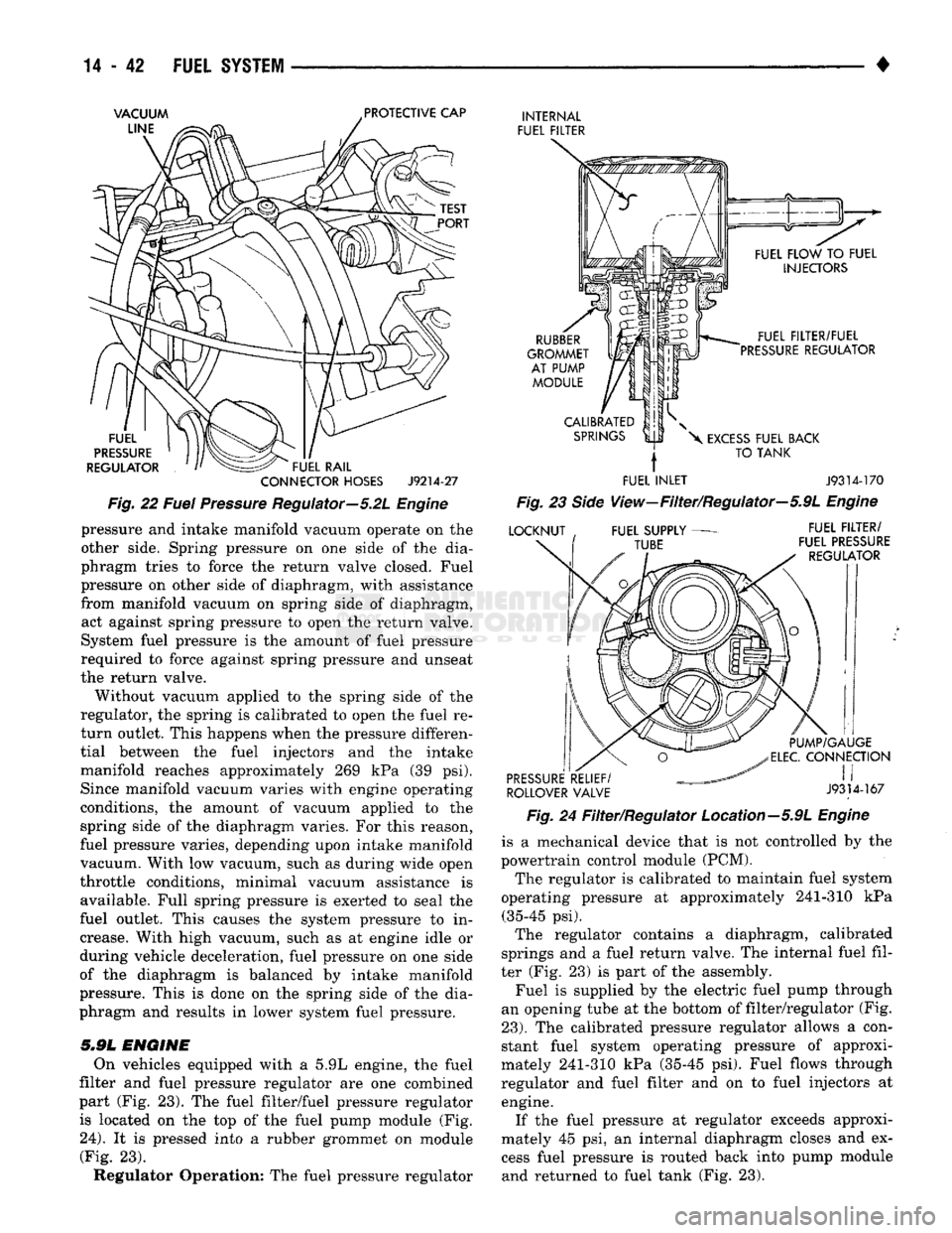
Fig.
22
Fuel
Pressure
Regulator—5.2L
Engine
pressure
and
intake manifold vacuum operate
on the
other side. Spring pressure
on one
side
of the
dia
phragm tries
to
force
the
return valve closed. Fuel
pressure
on
other side
of
diaphragm, with assistance from manifold vacuum
on
spring side
of
diaphragm, act against spring pressure
to
open
the
return valve.
System fuel pressure
is the
amount
of
fuel pressure
required
to
force against spring pressure
and
unseat
the return valve.
Without vacuum applied
to the
spring side
of the
regulator,
the
spring
is
calibrated
to
open
the
fuel
re
turn outlet. This happens when
the
pressure differen
tial between
the
fuel injectors
and the
intake
manifold reaches approximately
269 kPa (39 psi).
Since manifold vacuum varies with engine operating
conditions,
the
amount
of
vacuum applied
to the
spring side
of the
diaphragm varies.
For
this reason,
fuel pressure varies, depending upon intake manifold
vacuum. With
low
vacuum, such
as
during wide open
throttle conditions, minimal vacuum assistance
is
available. Full spring pressure
is
exerted
to
seal
the
fuel outlet. This causes
the
system pressure
to in
crease. With high vacuum, such
as at
engine idle
or
during vehicle deceleration, fuel pressure
on one
side
of
the
diaphragm
is
balanced
by
intake manifold
pressure. This
is
done
on the
spring side
of the
dia
phragm
and
results
in
lower system fuel pressure.
5.9L
ENGINE
On vehicles equipped with
a 5.9L
engine,
the
fuel
filter and fuel pressure regulator
are one
combined
part
(Fig. 23). The
fuel filter/fuel pressure regulator is located
on the top of the
fuel pump module
(Fig.
24).
It is
pressed into
a
rubber grommet
on
module (Fig.
23).
Regulator Operation:
The
fuel pressure regulator
RUBBER
GROMMET AT PUMP MODULE FUEL FILTER/FUEL
PRESSURE REGULATOR
CALIBRATED SPRINGS
X
EXCESS FUEL BACK
TO TANK
FUEL INLET J9314-170
Fig.
23
Side
View—Filter/Regulator—5.9L
Engine
LOCKNUT FUEL SUPPLY
TUBE FUEL FILTER/
FUEL PRESSURE REGULATOR PUMP/GAUGE
ELEC.
CONNECTION
PRESSURE RELIEF/
, I I
ROLLOVER VALVE
J9314-167
Fig.
24
Filter/Regulator Location—5.9L
Engine
is
a
mechanical device that
is not
controlled
by the
powertrain control module (PCM).
The regulator
is
calibrated
to
maintain fuel system
operating pressure
at
approximately 241-310
kPa
(35-45
psi).
The regulator contains
a
diaphragm, calibrated
springs
and a
fuel return valve.
The
internal fuel fil
ter
(Fig. 23) is
part
of the
assembly. Fuel
is
supplied
by the
electric fuel pump through
an opening tube
at the
bottom
of
filter/regulator
(Fig.
23).
The
calibrated pressure regulator allows
a
con
stant fuel system operating pressure
of
approxi
mately 241-310
kPa
(35-45
psi).
Fuel flows through
regulator
and
fuel filter
and on to
fuel injectors
at
engine. If
the
fuel pressure
at
regulator exceeds approxi
mately
45 psi, an
internal diaphragm closes
and ex
cess fuel pressure
is
routed back into pump module and returned
to
fuel tank
(Fig. 23).
Page 883 of 1502
MULTI-PORT
FUEL
INJECTION
(MPI)-COMPONENT
REMOVAL/INSTALLATION
—EXCEPT DIESEL
INDEX
page
Accelerator Pedal
and Throttle
Cable
. 64
Air Conditioning (A/C) Clutch Relay
64
Air
Filter/Filter
Housing
64
Automatic Shut Down (ASD) Relay
. 64
Brake
Switch
64
Camshaft
Position
Sensor
..................
64
Charge
Air
Temperature
Sensor
64
Crankshaft Position
Sensor
64
Engine
Coolant Temperature
Sensor
65
EVAP
Canister Purge Solenoid
65
Fuel
Filter
65
Fuel Filter/Fuel Pressure Regulator—5.9L Engine
. 65
Fuel Injector(S)
67
Fuel Pressure Regulator
67
Fuel Pump Module
68
Fuel Pump Relay
68
ACCELERATOR
PEDAL
AND THROTTLE
CABLE
Refer
to
the
Accelerator Pedal
and
Throttle Cable
section
of
this group
for
removal/installation proce
dures.
AIR
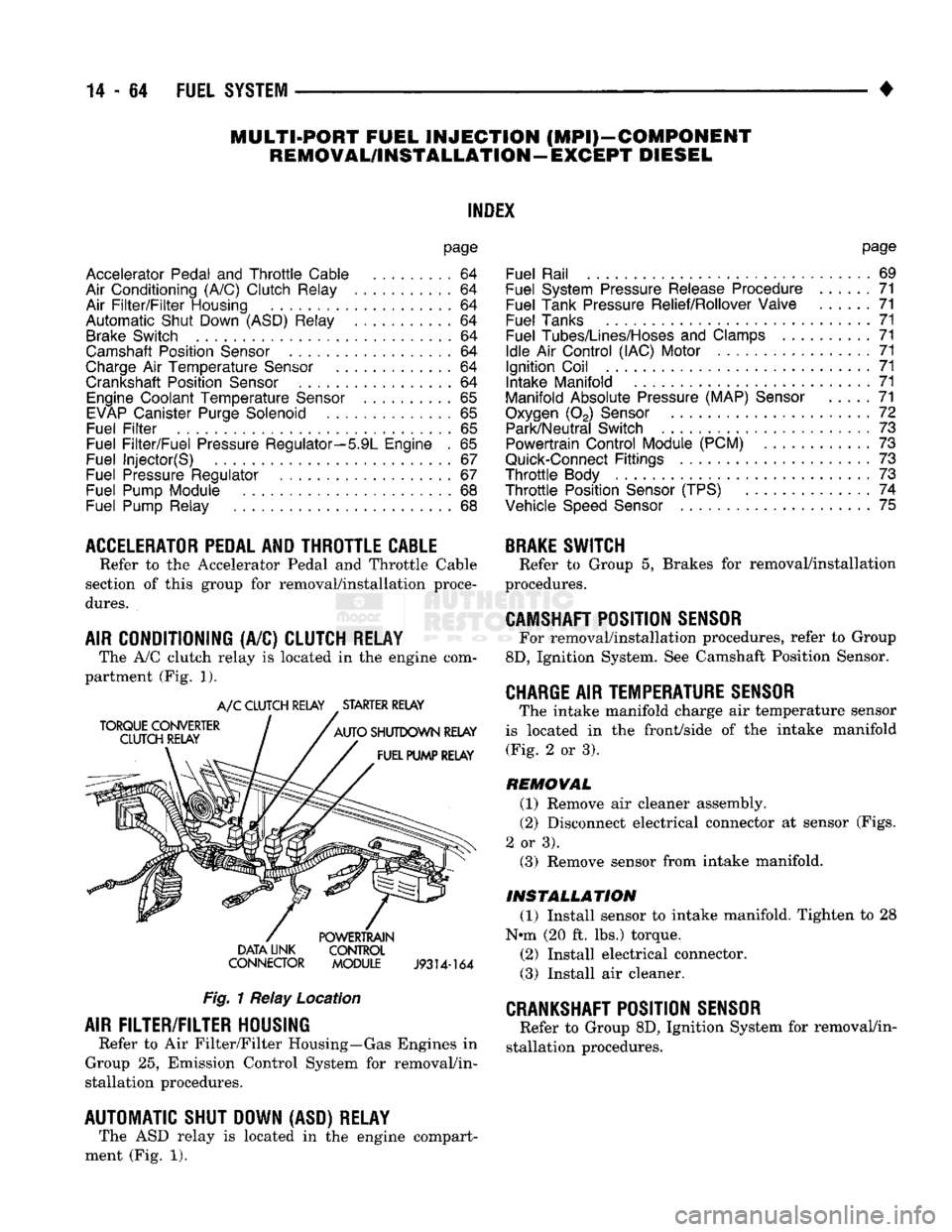
CONDITIONING (A/C) CLUTCH RELAY The A/C clutch relay
is
located
in
the
engine com
partment (Fig.
1).
A/C CLUTCH RELAY STARTER RELAY
DATA LINK CONTROL
CONNECTOR MODULE
J9314-164
Fig.
1 Relay Location
AIR
FILTER/FILTER
HOUSING
Refer
to
Air Filter/Filter Housing—Gas Engines
in
Group
25,
Emission Control System
for
removal/in
stallation procedures.
AUTOMATIC SHUT DOWN (ASD) RELAY The ASD relay
is
located
in
the
engine compart
ment (Fig.
1).
page
Fuel Rail
69
Fuel System Pressure Release Procedure
......
71
Fuel Tank Pressure Relief/Rollover Valve
71
Fuel Tanks
71
Fuel
Tubes/Lines/Hoses
and
Clamps
71
Idle
Air
Control (IAC) Motor
71
Ignition Coil
71
Intake Manifold
71
Manifold Absolute Pressure (MAP)
Sensor
71
Oxygen
(02)
Sensor
72
Park/Neutral Switch
. 73
Powertrain Control Module (PCM)
73
Quick-Connect
Fittings
73
Throttle
Body
73
Throttle
Position
Sensor
(TPS)
......
74
Vehicle
Speed
Sensor
75
BRAKE
SWITCH
Refer
to
Group
5,
Brakes
for
removal/installation
procedures.
CAMSHAFT
POSITION
SENSOR
For removal/installation procedures, refer
to
Group
8D,
Ignition System. See Camshaft Position Sensor.
CHARGE
AIR
TEMPERATURE SENSOR
The intake manifold charge
air
temperature sensor
is located
in the
front/side
of
the
intake manifold (Fig.
2
or
3).
REMOVAL
(1) Remove
air
cleaner assembly.
(2) Disconnect electrical connector
at
sensor (Figs.
2
or
3). (3) Remove sensor from intake manifold.
INSTALLATION
(1) Install sensor
to
intake manifold. Tighten
to 28
Nnn (20
ft.
lbs.) torque.
(2) Install electrical connector.
(3) Install
air
cleaner.
CRANKSHAFT
POSITION
SENSOR
Refer
to
Group 8D, Ignition System
for
removal/in
stallation procedures.
Page 885 of 1502
14
- 66
FUEL
SYSTEM
REMOVAL
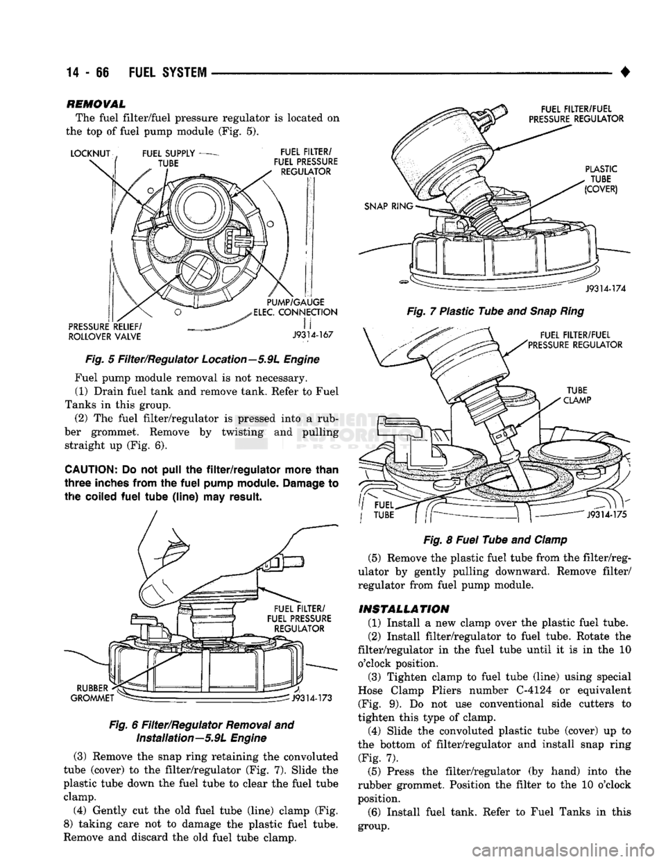
The fuel filter/fuel pressure regulator is located on
the top of fuel pump module (Fig. 5).
ROLLOVER
VALVE
J9314-167
Fig.
5 Filter/Regulator Location—5.9L
Engine
Fuel pump module removal is not necessary. (1) Drain fuel tank and remove tank. Refer to Fuel
Tanks in this group. (2) The fuel filter/regulator is pressed into a rub
ber grommet. Remove by twisting and pulling straight up (Fig. 6).
CAUTION;
Do not pull the
filter/regulator
more
than
three
inches
from
the
fuel
pump
module.
Damage
to
the
coiled
fuel
tube
(line)
may
result.
Fig.
6 Filter/Regulator
Removal
and Installation—5.9L
Engine
(3) Remove the snap ring retaining the convoluted
tube (cover) to the filter/regulator (Fig. 7). Slide the
plastic tube down the fuel tube to clear the fuel tube clamp.
(4) Gently cut the old fuel tube (line) clamp (Fig.
8) taking care not to damage the plastic fuel tube.
Remove and discard the old fuel tube clamp.
Fig.
7 Plastic Tube and
Snap
Ring
Fig.
8
Fuel
Tube and
Clamp
(5) Remove the plastic fuel tube from the filter/reg
ulator by gently pulling downward. Remove filter/
regulator from fuel pump module.
INSTALLATION
(1) Install a new clamp over the plastic fuel tube.
(2) Install filter/regulator to fuel tube. Rotate the
filter/regulator in the fuel tube until it is in the 10 o'clock position. (3) Tighten clamp to fuel tube (line) using special
Hose Clamp Pliers number C-4124 or equivalent (Fig. 9). Do not use conventional side cutters to
tighten this type of clamp.
(4) Slide the convoluted plastic tube (cover) up to
the bottom of filter/regulator and install snap ring (Fig. 7).
(5) Press the filter/regulator (by hand) into the
rubber grommet. Position the filter to the 10 o'clock
position.
(6) Install fuel tank. Refer to Fuel Tanks in this
group.
Page 896 of 1502
•
FUEL
SYSTEM
14-77
FUEL FROM SUPPLY TANK
LIFT
PUMP
LOW
PRESSURE
SUPPLY LINE
FUEL/WATER SEPARATOR FILTER
4A. FUEL HEATER
4B. FUEL/WATER DRAIN VALVE
FUEL/WATER SEPARATOR FILTER
W.I.F. (WATER
IN
FUEL) SENSOR
CHARGE
AIR
TEMP. SENSOR
BLEED
SCREW
LOW
PRESSURE
SUPPLY LINE
INJECTION PUMP
TURBO BOOST CONTROL LINE POWERTRAIN CONTROL MODULE
FUEL DRAIN MANIFOLD
(RETURN FUEL
TO
TANK)
HIGH
PRESSURE
LINES
INJECTORS
KSB
SOLENOID
MANUAL SHUT DOWN LEVER
TDC TIMING
PIN
AIR TEMP. SWITCH
NOTE: #10 CONTROLS INTAKE HEATER,
KSB
VALVE, FUEL HEATER,
WIF
SENSOR
J9314-179
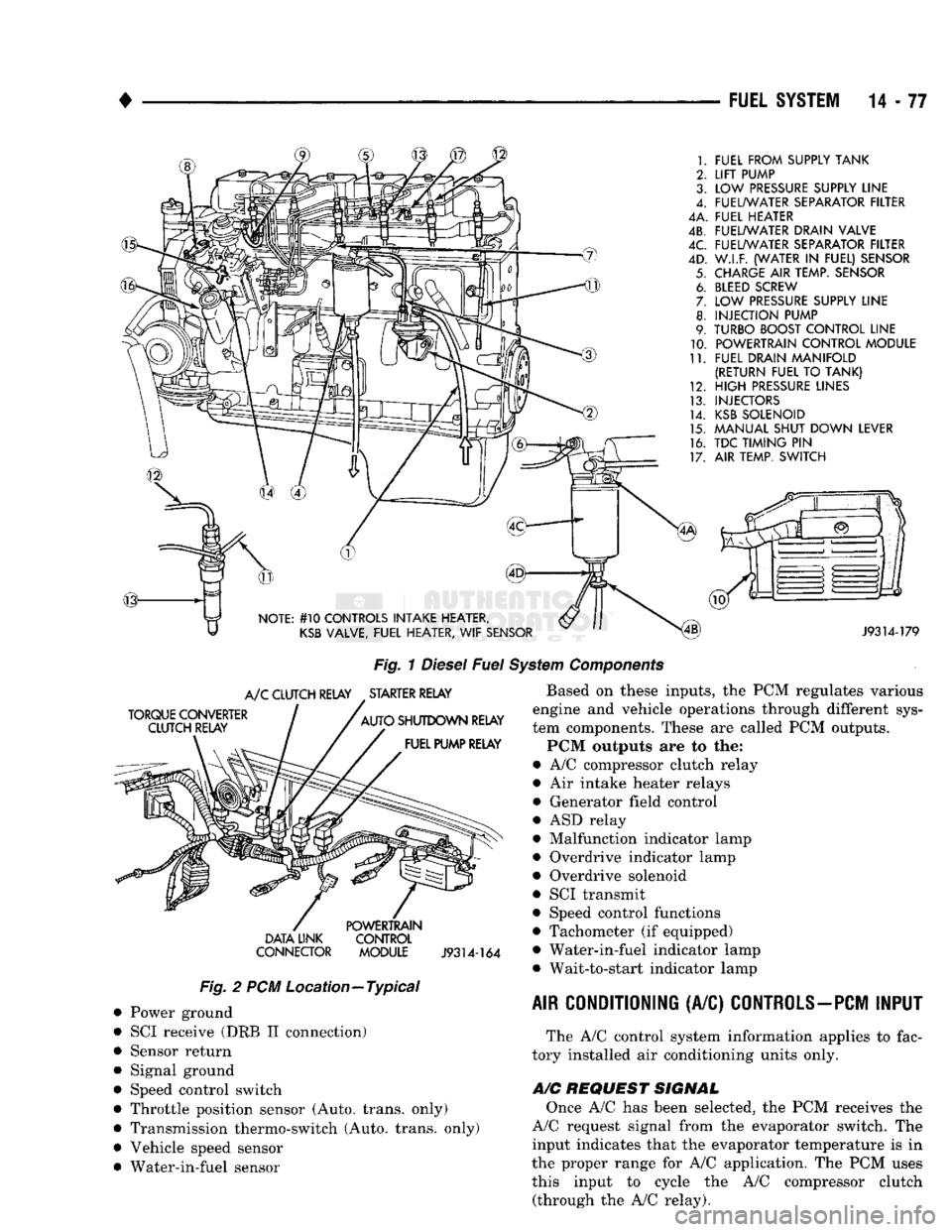
Fig.
1
Diesel
Fuel
System
Components
TORQUE CONVERTER CLUTCH RELAY
A/C
CLUTCH RELAY STARTER RELAY
AUTO SHUTDOWN RELAY FUEL PUMP RELAY DATA UNK
CONNECTOR POWERTRAIN
CONTROL
MODULE
J9314-164
Fig.
2 PCM Location—Typical Power ground
SCI receive (DRB II connection)
Sensor return
Signal ground
Speed control switch
Throttle position sensor (Auto, trans, only)
Transmission thermo-switch (Auto, trans, only)
Vehicle speed sensor
Water-in-fuel sensor Based on these inputs, the PCM regulates various
engine and vehicle operations through different sys
tem components. These are called PCM outputs.
PCM outputs are to the:
• A/C compressor clutch relay
• Air intake heater relays
• Generator field control
• ASD relay
• Malfunction indicator lamp
• Overdrive indicator lamp
• Overdrive solenoid
• SCI transmit
• Speed control functions
• Tachometer (if equipped)
• Water-in-fuel indicator lamp • Wait-to-start indicator lamp
AIR CONDITIONING
(A/C)
CONTROLS-PCM
INPUT
The A/C control system information applies to fac
tory installed air conditioning units only.
A/C
REQUEST SIGNAL
Once A/C has been selected, the PCM receives the
A/C request signal from the evaporator switch. The input indicates that the evaporator temperature is in
the proper range for A/C application. The PCM uses this input to cycle the A/C compressor clutch (through the A/C relay).
Page 899 of 1502
14 - 80
FUEL SYSTEM
•
SCI
RECEIVE-PCM
INPUT
The serial communication interface (SCI) receive
and transmit outputs allow the PCM to communicate
with the DRB II scan tool.
SENSOR
RETURN-PCM
INPUT
Sensor return provides a low noise ground refer
ence for all system sensors.
SIGNAL
GROUND-PCM
INPUT
Provides a common ground for the input signals.
SPEED
CONTROL-PCM
INPUT
The PCM regulates the speed control system based
on inputs it receives. The speed control operating
range is from 35 to 85 mph. Inputs that effect speed control operation are:
• Park/neutral switch
• Vehicle speed sensor
• Throttle position sensor
• Engine speed sensor
• Brake switch
THROTTLE
POSITION SENSOR (TPS) —PCM
INPUT
The throttle position sensor is not used with man
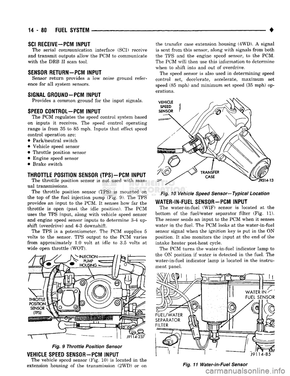
ual transmissions. The throttle position sensor (TPS) is mounted on
the top of the fuel injection pump (Fig. 9). The TPS
provides an input to the PCM. It senses how far the
throttle is open (past the idle position). The PCM uses the TPS input, along with vehicle speed sensor and engine speed sensor inputs to determine 3-4 up
shift (overdrive) and 4-3 downshift. The TPS is a potentiometer. The PCM supplies 5
volts to the sensor. TPS output to the PCM varies
from approximately 1.0 volt at idle to 3.5 volts at
wide open throttle (WOT). T
J9114-237
Fig.
9
Throttle
Position
Sensor
VEHICLE SPEED SENSOR-PCM
INPUT
The vehicle speed sensor (Fig. 10) is located in the
extension housing of the transmission (2WD) or on the transfer case extension housing (4WD). A signal
is sent from this sensor, along with signals from both
the TPS and the engine speed sensor, to the PCM.
The PCM will then use this information to determine
when to shift into and out of overdrive.
The speed sensor is also used in determining speed
control set, decelerate, accelerate, maximum set
speed (85 mph) and minimum set speed (35 mph) op
erations.
VEHICLE
SPEED
SENSOR
Fig.
10 Vehicle
Speed
Sensor—Typical Location
WATER-IN-FUEL SENSOR-PCM
INPUT
The water-in-fuel (WIF) sensor is located at the
bottom of the fuel/water separator filter (Fig. 11). The sensor sends an input to the PCM when it senses
water in the fuel. The PCM looks at the water-in-fuel sensor signal when the ignition key is put in the ON
position. It also monitors the input at the end of the intake heater post-heat cycle. The PCM turns the water-in-fuel indicator lamp to
the ON position if water is detected in the fuel. The
water-in-fuel indicator lamp is located in the instru ment panel.
J91 14-85
Fig.
11 Water-in-Fuel
Sensor
Page 1479 of 1502
25
- 2
EMISSION
CONTROL
SYSTEMS
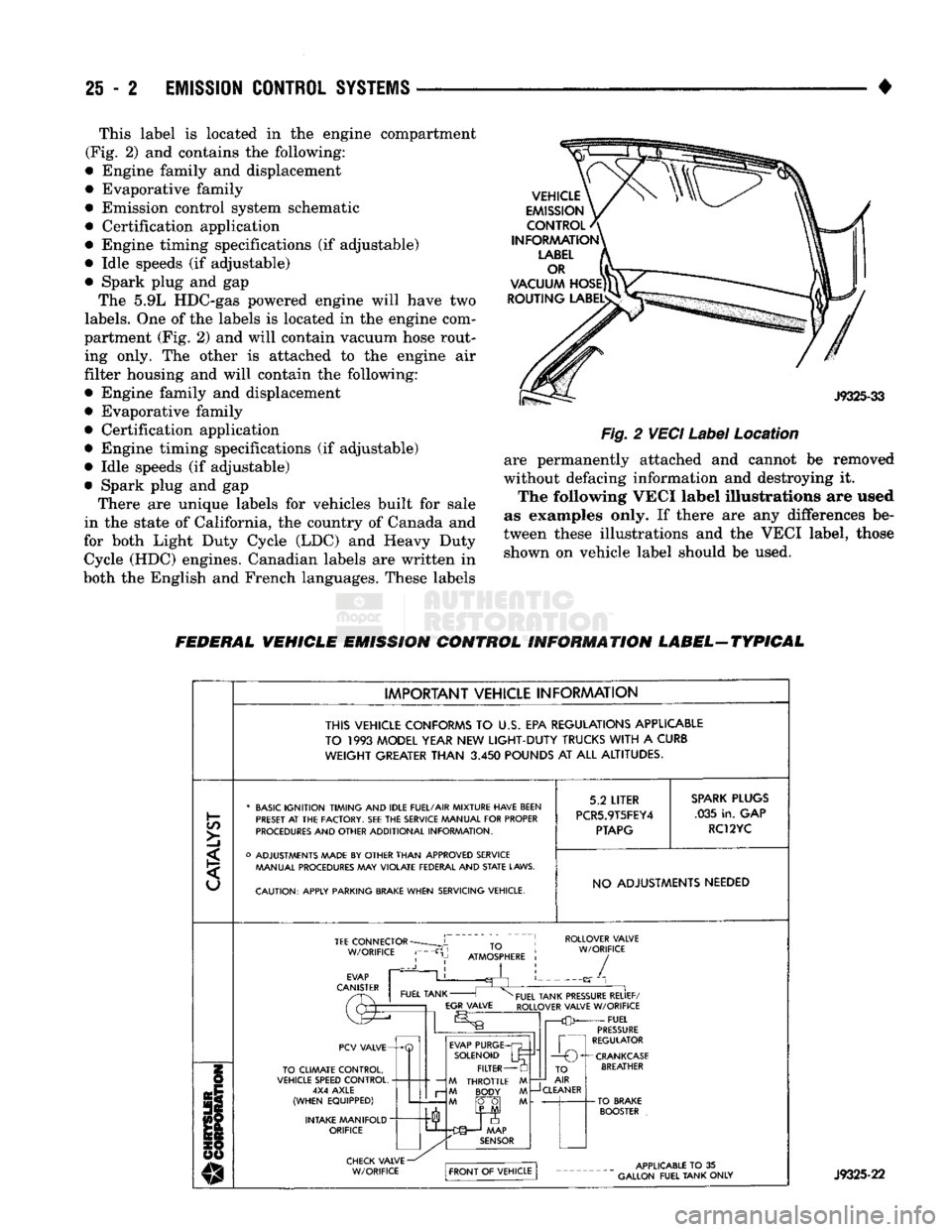
• This label is located in the engine compartment
(Fig. 2) and contains the following:
• Engine family and displacement
• Evaporative family
• Emission control system schematic
• Certification application
• Engine timing specifications (if adjustable)
• Idle speeds (if adjustable)
• Spark plug and gap The 5.9L HDC-gas powered engine will have two
labels.
One of the labels is located in the engine com
partment (Fig. 2) and will contain vacuum hose rout ing only. The other is attached to the engine air
filter housing and will contain the following:
• Engine family and displacement
• Evaporative family
• Certification application
• Engine timing specifications (if adjustable)
• Idle speeds (if adjustable)
• Spark plug and gap There are unique labels for vehicles built for sale
in the state of California, the country of Canada and
for both Light Duty Cycle (LDC) and Heavy Duty Cycle (HDC) engines. Canadian labels are written in
both the English and French languages. These labels
Fig.
2
VECI
Label
Location
are permanently attached and cannot be removed
without defacing information and destroying it. The following VECI label illustrations are used
as examples only. If there are any differences be
tween these illustrations and the VECI label, those shown on vehicle label should be used.
FEDERAL VEHICLE EMISSION CONTROL INFORMATION LABEL-TYPICAL
IMPORTANT VEHICLE INFORMATION
THIS VEHICLE CONFORMS
TO U.S. EPA
REGULATIONS APPLICABLE
TO
1993
MODEL YEAR
NEW
LIGHT-DUTY
TRUCKS
WITH
A
CURB
WEIGHT
GREATER
THAN
3.450
POUNDS
AT ALL
ALTITUDES.
C/5
>]
* BASIC IGNITION TIMING AND IDLE FUEL/AIR MIXTURE HAVE BEEN
PRESET
AT THE
FACTORY.
SEE THE
SERVICE MANUAL FOR PROPER
PROCEDURES AND OTHER ADDITIONAL INFORMATION.
o ADJUSTMENTS MADE
BY
OTHER THAN APPROVED SERVICE MANUAL PROCEDURES
MAY
VIOLATE FEDERAL AND
STATE
LAWS.
CAUTION: APPLY PARKING
BRAKE
WHEN SERVICING VEHICLE. 5.2
LITER
PCR5.9T5FEY4
PTAPG
SPARK
PLUGS
.035 in. GAP
RC12YC
NO ADJUSTMENTS NEEDED TEE
CONNECTOR
W/ORIFICE ROLLOVER VALVE
W/ORIFICE
PCV VALVE-
TO CLIMATE CONTROL,
VEHICLE SPEED CONTROL, 4X4 AXLE
(WHEN EQUIPPED)
INTAKE MANIFOLD
"
ORIFICE EVAP PURGE
SOLENOID FILTER
M THROTTLE M M BODY M
M fO~0| M TO
AIR
—J
CLEANER
-CRANKCASE
BREATHER J9325-22