1993 DODGE TRUCK engines
[x] Cancel search: enginesPage 4 of 1502
GROUP TAB LOCATOR
Introduction
0
Lubrication
and
Maintenance
2
Front Suspension
and
Axle
3
Rear Suspension
and
Axles
5
Brakes
6
Clutch
7
Cooling System
8
Electrical
9
Engines
11
Exhaust System
and
Intake
Manifold
13
Frame
and Bumpers
14
Fuel
System
16
Propeller Shafts
19
Steering
21
Transmission
and
Transfer Case
22
Wheels and Tires
23
Body Components
24
Heating
and Air
Conditioning
25
Emission Control Systems Component and System Index
Service Manual Comment Forms (Rear
of
Manual)
Page 7 of 1502
2 INTRODUCTION
•
MFD
BY
GAWR
FRONT
GAWR REAR
CHRYSLER
CORPORATION
DATE
OF MFR
GVWR
WITH
TIRES
WITH
TIRES
RIMS
AT
RIMS
AT
PSI
COLD
PSI
COLD
THIS
VEHICLE CONFORMS
TO
ALL APPLICABLE FEDERAL MOTOR VEHICLE SAFETY
STANDARDS
IN
EFFECT ON
THE
DATE
OF
MANUFACTURE SHOWN ABOVE.
SINGLE
DUAL
MDH:
BAR
CODE
VEHICLE MADE
IN
4648503
J9HN-25
Fig. 1 Vehicle Safety Certification Label
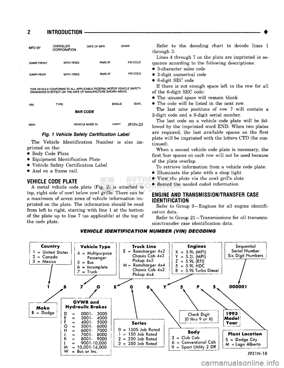
The Vehicle Identification Number is also im
printed on the:
• Body Code Plate
• Equipment Identification Plate
• Vehicle Safety Certification Label
• And on a frame rail.
VEHICLE CODE PLATE
A metal vehicle code plate (Fig. 2) is attached to
top,
right side of cowl below cowl grille. There can be a maximum of seven rows of vehicle information im
printed on the plate. The information should be read
from left to right, starting with line 1 at the bottom
of the plate up to line 7 (as applicable) at the top of
the code plate. Refer to the decoding chart to decode lines 1
through 3.
Lines 4 through 7 on the plate are imprinted in se
quence according to the following descriptions:
• 3-character sales code • 3-digit numerical code
• 6-digit SEC code If there is not enough space left in the row for all
of the 6-digit SEC code:
• The unused space will remain blank
• The code will be listed in the next row.
The last nine positions of row 7 will contain a
2-digit code and a 6-digit serial number.
The last code on a vehicle code plate will be fol
lowed by the imprinted word END. When two plates
are required, the last available spaces on the first
plate will be imprinted with the letters CTD (for con tinued).
When a second vehicle code plate is necessary, the
first four spaces on each row will not be used because of the plate overlap.
To retrieve information from a vehicle code plate:
• Illuminate the plate with a shop light
• View the plate via the cowl grille slots
• Record the needed coded information.
ENGINE AND TRANSMISSION/TRANSFER CASE
IDENTIFICATION
Refer to Group 9—Engines for all engine identifi
cation data. Refer to Group 21—Transmissions for all transmis
sion/transfer case identification data.
VEHICLE IDENTIFICATION NUMBER (VIN) DECODING
Country
1
=
United States
2
=
Canada
3
=
Mexico Vehicle Type
4
=
Multipurpose
Passenger
5
=
Bus
6
=
Incomplete
7
=
Truck
GVWR
and
Hydraulic Brakes
0001 3001
4001
5001 6001
7001 8001
9001
10,001
Bus
or I
3000
4000
5000 6000
7000 8000
9000
10,000
14,000
nc.
Truck Line
E
=
Ramcharger
4x2
Chassis
Cab
4x2
Pickup
4x2
M
=
Ramcharger
4x4
Chassis
Cab
4x2
Pickup
4x4
Engines
X
=
3.9L
(MPI)
Y = 5.2L
(MPI)
Z
=
5.9L
(EFI)
5
=
5.9L HDC
8
=
5.9L Turbo Diesel Sequential
Serial Number
Six
Digit Numbers
Series
0 =
150S Job Rated
1
= 150
Job Rated
2
= 250
Job Rated
3
= 350
Job Rated
Body
3
=
Club Cab 6
=
Conventional Cab
9
=
Sport
Utility
2 DR
Plant Location
S
=
Dodge City
M
=
Lago
Alberto J931N-18
Page 21 of 1502
0 - 2
LUBRICATION
AND
MAINTENANCE
• Commercial service
When a vehicle is continuously subjected to severe
driving conditions, lubricate:
• Body components
• All the driveline coupling joints
• Steering linkage More often than normal driving conditions
DUSTY
AREAS
With this type of severe driving condition, special
care should be given to the:
• Engine air cleaner filter
• PCV filter
• Crankcase ventilation system
• Brake booster control valve air filter. Verify that the filters and the associated compo
nents are clean. Also verify that they are functioning
effectively. This will minimize the amount of abra sive particles that enter the engine.
OFF-ROAD
(4WD)
OPERATION
After off-road (4WD) operation, inspect the under
side of the vehicle. Inspect the:
• Tires
• Body structure
• Steering components
• Suspension components • Exhaust system
• Threaded fasteners
HARSH
SURFACE ENVIRONMENTS
After extended operation in harsh environments,
the brake drums, brake linings, and rear wheel bear ings should be inspected and cleaned. This will pre
vent wear and erratic brake action.
ROUTINE MAINTENANCE
The following routine maintenance is recommended
on a monthly basis: TIRES—Inspect the tires for unusual wear/damage.
Determine if the inflation pressure is adequate for
the vehicle load. BATTERY—Inspect and clean the terminals.
Tighten the terminals if necessary. FLUIDS—Determine if the component fluid levels
are acceptable. Add fluid, if necessary. LIGHTS/ELECTRICAL—Test all the electrical sys
tems in the vehicle for proper operation. It is also recommended that the engine oil and the
washer fluid level be determined at each fuel fill-up.
VEHICLE
NOISE CONTROL
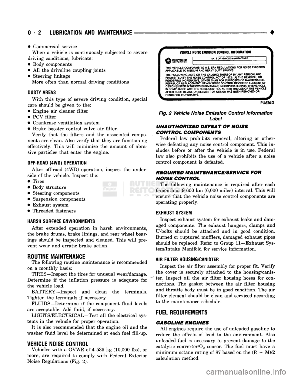
Vehicles with a GVWR of 4 535 kg (10,000 lbs), or
more, are required to comply with Federal Exterior Noise Regulations (Fig. 2).
VEHICLE
NOISE
EMISSION
CONTROL INFORMATION
DATE
OF
VEHICLE
MANUFACTURE
THIS
VEHICLE CONFORMS
TO
U.S. EPA REGULATIONS FOR NOISE EMISSION
APPLICABLE
TO
MEDIUM
AND HEAVY
DUTY
TRUCKS. THE
FOLLOWING
ACTS OR THE CAUSING THEREOF BY ANY PERSON ARE PROHIBITED BY THE NOISE CONTROL ACT
OF 1972. (A) THE
REMOVAL
OR
RENDERING
INOPERATIVE, OTHER
THAN
FOR
PURPOSES
OF
MAINTENANCE,
REPAIR.
OR REPLACEMENT, OF ANY NOISE CONTROL DEVICE OR ELEMENT OF
DESIGN
(LISTED
IN
THE
OWNERS
MANUAL)
INCORPORATED
INTO
THIS
VEHICLE
IN COMPLIANCE
WITH
THE NOISE CONTROL
ACT:
(B) THE
USE
OF
THIS
VEHICLE
AFTER SUCH DEVICE
OR
ELEMENT
OF
DESIGN HAS BEEN REMOVED
OR
RENDERED
INOPERATIVE.
PU626D
Fig.
2 Vehicle
Noise
Emission
Control Information
Label
UNAUTHORIZED
DEFEAT
OF
NOISE
CONTROL COMPONENTS
Federal law prohibits removal, altering or other
wise defeating any noise control component. This in
cludes before or after the vehicle is in use. Federal
law also prohibits the use of a vehicle after a noise
control component is defeated.
REQUIRED MAINTENANCE/SERVICE
FOR
NOISE
CONTROL
The following maintenance is required after each
6-month or 9 600 km (6,000 miles) interval. This will
ensure that the vehicle noise control components are
operating properly.
EXHAUST SYSTEM
Inspect exhaust system for exhaust leaks and dam
aged components. The exhaust hangers, clamps and
U-bolts should be attached and in good condition.
Burned or ruptured mufflers, damaged exhaust pipes should be replaced. Refer to Group 11—Exhaust Sys
tem/Intake Manifold for service information.
AIR
FILTER
HOUSING/CANISTER
Inspect the air filter assembly for proper fit. Verify
the cover is securely attached to the housing/canis
ter. Inspect all the air filter housing hoses for con nections. The gasket between the air filter housing and throttle body must be in good condition. The air
filter element should be clean and serviced according
to the maintenance schedule.
FUEL
REQUIREMENTS
GASOLINE
ENGINES
All engines require the use of unleaded gasoline to
reduce the effects of lead to the environment. Also unleaded fuel is necessary to prevent damage to the
catalytic converter/02 sensor. The fuel must have a
minimum octane rating of 87 based on the (R + M)/2
calculation method.
Page 22 of 1502

•
LUBRICATION AND MAINTENANCE
0 - 3
CAUTION: UNLEADED FUEL ONLY must
be
used
in
vehicles equipped
with
a
catalyst emission
control
system.
All
vehicles have reminders
printed
on the
instrument
panel below
the
fuel
gauge
and on the
fuel
filler
door.
The
vehicles also have
fuel
filler
tubes
that
are
specially designed
to
accept only
the
small-diameter nozzles.
It is
illegal
to
bypass
the
design
of an
unleaded
fuel
filler
tube.
DIESEL ENGINES All
Ram
Truck
and Ram
Cab/Chassis Diesel
en
gines normally
can use
number
2D
Diesel fuel
for
most year-round operations.
A
fuel conforming
to
ASTM Specification D-975
is
recommended.
For ex
treme cold-weather, number
ID
Diesel fuel
is
recom mended.
CLASSIFICATION
OF
LUBRICANTS
Lubricating fluids
and
chassis lubricants
are
clas
sified according
to
standards recommended
by the:
• Society
of
Automotive Engineers
(SAE)
• American Petroleum Institute
(API)
• National Lubricating Grease Institute (NLGI)
ENGINE
OIL
SAE
VISCOSITY
GRADE
An
SAE
viscosity grade
is
used
to
specify
the
vis
cosity
of
engine
oil. SAE 30
specifies
a
single viscos
ity engine
oil.
Engine oils also have multiple viscosities. These
are specified with
a
dual
SAE
viscosity grade which
indicates
the
cold-to-hot temperature viscosity range (Fig.
3).
API
SERVICE
GRADE
The
API
Service Grade specifies
the
type
of
perfor
mance
the
engine
oil is
intended
to
provide.
The API
Service Grade specifications also apply
to
energy con
serving engine oils
(Fig. 3).
For maximum gasoline engine protection,
use API
Service Grade
SG,
SG/CD
or
SG/CE engine
oil.
For maximum Diesel engine protection,
use
API Service
CE or
SG/CE engine
oil.
GEAR LUBRICANTS A dual grade
is
also used
to
specify
the
viscosity
of
multi-purpose gear lubricants.
The
API
grade designation identifies gear lubri
cants
in
terms
of
recommended usage.
OIL
QUALITY
SAE
VISCOSITY
GRADE
FUEL
ECONOMY
NOTATION
J91004
Fig.
3 SAE Oil
Viscosity Grade
& API
Service
Grade
CHASSIS COMPONENT
AND
WHEEL BEARING
LUBRICANTS The chassis
and
wheel bearing lubricants
are
iden
tified
by the
NLGI Certification Symbol.
The
symbol
contains
a
coded designation. This identifies
the us
age
and
quality
of the
lubricant.
The letter
G
within
the
symbol designates wheel
bearing lubricant.
The
letter
L
designates chassis
lu
bricant. When
the
letters
are
combined,
the
lubricant can
be
used
for
dual applications.
Use
only lubricants
that display
the
NLGI Certification Symbol.
NATIONAL LUBRICATING
GREASE
INSTITUTE
NLGI
AUTOMOTIVE
WHEEL BEARING
&
CHASSIS LUBRICANT
GC-LB
-CERTIFICATION
SYMBOL
—
USAGE
AND
QUALITY
DESIGNATION
J920W7
Fig.
4
NLGI
Lubricant Container
Certification/
Identification
Symbol
LUBRICATION
AND
REPLACEMENT
PARTS
RECOMMENDATION
Ram Trucks
are
engineered
to
provide many years
of dependable operation. However, lubrication service
and maintenance
are
required
for
each vehicle. When
necessary, MOPAR®brand lubricants
and
genuine
re
placement parts
are
recommended.
Page 28 of 1502
•
LUBRICATION AND MAINTENANCE
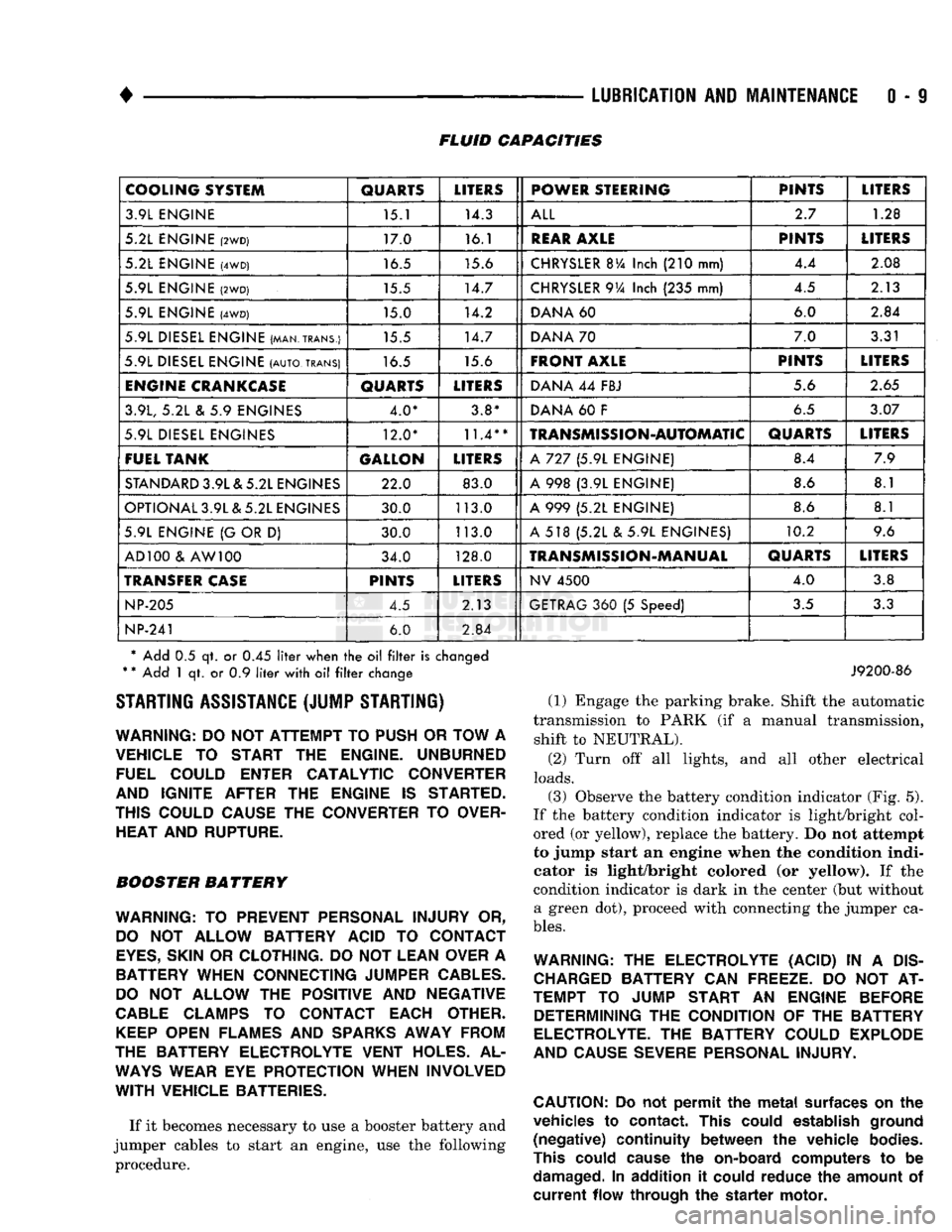
0 - 9 FLUID CAPACITIES
COOLING SYSTEM
QUARTS
LITERS
POWER STEERING PINTS
LITERS
3.9L ENGINE 15.1 14.3
ALL
2.7
1.28
5.2L ENGINE
(2WD)
17.0 16.1
REAR
AXLE
PINTS
LITERS
5.2L ENGINE
(4WD)
16.5 15.6
CHRYSLER
BVa
Inch
(210
mm) 4.4
2.08
5.9L ENGINE
(2WD)
15.5 14.7
CHRYSLER
9Va
Inch
(235
mm) 4.5
2.13
5.9L ENGINE
(4WD)
15.0 14.2
DANA
60 6.0
2.84
5.9L DIESEL ENGINE (MAN.TRANS.) 15.5 14.7
DANA
70 7.0
3.31
5.9L DIESEL ENGINE
(AUTO,
TRANS)
16.5 15.6
FRONT AXLE
PINTS
LITERS
ENGINE
CRANKCASE
QUARTS
LITERS
DANA
44
FBJ 5.6
2.65
3.9L,
5.2L & 5.9
ENGINES 4.0* 3.8*
DANA
60 F
6.5
3.07
5.9L DIESEL ENGINES 12.0*
11.4**
TRANSMISSION-AUTOMATIC
QUARTS
LITERS
FUEL TANK GALLON
LITERS
A
727 (5.9L
ENGINE) 8.4
7.9
STANDARD
3.9L & 5.2L ENGINES 22.0 83.0
A
998 (3.9L
ENGINE) 8.6
8.1
OPTIONAL 3.9L & 5.2L ENGINES 30.0 113.0
A
999 (5.2L
ENGINE) 8.6
8.1
5.9L ENGINE
{G
OR
D)
30.0 113.0
A
518 (5.2L & 5.9L
ENGINES) 10.2
9.6
AD 100
&
AW 100 34.0 128.0
TRANSMISSION-MANUAL
QUARTS
LITERS
TRANSFER
CASE
PINTS
LITERS
NV
4500
4.0
3.8
NP-205
4.5 2.13
GETRAG
360 (5
Speed)
3.5
3.3
NP-241
6.0
2.84
* Add
0.5 qt. or 0.45
liter
when
the oil filter
is
changed
*
*
Add
1 qt. or 0.9
liter
with
oil filter
change STARTING ASSISTANCE (JUMP STARTING)
WARNING:
DO NOT
ATTEMPT
TO
PUSH
OR
TOW
A
VEHICLE
TO
START
THE
ENGINE. UNBURNED FUEL COULD ENTER CATALYTIC CONVERTER
AND IGNITE AFTER
THE
ENGINE
IS
STARTED.
THIS COULD CAUSE
THE
CONVERTER
TO
OVER HEAT AND RUPTURE.
BOOSTER BATTERY
WARNING:
TO
PREVENT PERSONAL INJURY
OR,
DO
NOT
ALLOW BATTERY ACID
TO
CONTACT
EYES,
SKIN
OR
CLOTHING.
DO NOT
LEAN OVER
A
BATTERY WHEN CONNECTING JUMPER
CABLES.
DO
NOT
ALLOW
THE
POSITIVE
AND
NEGATIVE
CABLE
CLAMPS
TO
CONTACT EACH OTHER.
KEEP
OPEN FLAMES
AND
SPARKS
AWAY FROM
THE BATTERY ELECTROLYTE VENT HOLES.
AL
WAYS
WEAR
EYE
PROTECTION WHEN INVOLVED
WITH
VEHICLE BATTERIES.
If it becomes necessary to use a booster battery and
jumper cables to start an engine, use the following procedure.
J9200-86
(1) Engage the parking brake. Shift the automatic
transmission to PARK (if a manual transmission, shift to NEUTRAL).
(2) Turn off all lights, and all other electrical
loads.
(3)
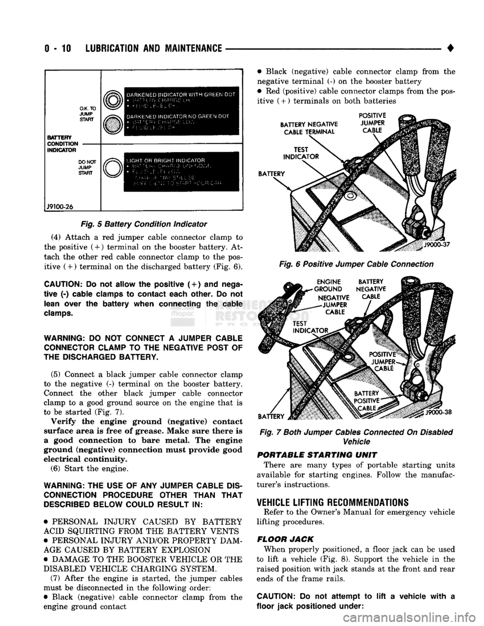
Observe the battery condition indicator (Fig. 5).
If the battery condition indicator is light/bright col
ored (or yellow), replace the battery. Do not attempt
to jump start an engine when the condition indi
cator is light/bright colored (or yellow). If the
condition indicator is dark in the center (but without a green dot), proceed with connecting the jumper ca
bles.
WARNING:
THE
ELECTROLYTE (ACID)
IN A
DIS
CHARGED
BATTERY
CAN
FREEZE.
DO NOT AT
TEMPT
TO
JUMP START
AN
ENGINE BEFORE DETERMINING
THE
CONDITION
OF THE
BATTERY
ELECTROLYTE.
THE
BATTERY COULD EXPLODE
AND CAUSE SEVERE PERSONAL INJURY.
CAUTION:
Do not
permit
the
metal
surfaces
on the
vehicles
to
contact.
This
could
establish
ground
(negative)
continuity
between
the
vehicle
bodies.
This
could
cause
the
on-board
computers
to be
damaged.
In
addition
it
could
reduce
the
amount
of
current
flow
through
the
starter
motor.
Page 29 of 1502
0-10
LUBRICATION
AND
MAINTENANCE
•
O.K.TO
JUMP
START BATTERY
CONDITION
INDICATOR DO NOT
JUMP
START J9100-26 DARKENED
INDICATOR
WITH
GREEN
DOT
•
LETTERS
Uk-
FLUID
Lt- E:L .
DARKENED
INDICATOR
NO
GREEN
DOT •
BATTERY CHARGE
10'//
• Ft UID
L
EVEl
OK
LIGHT
OR
BRIGHT
INDICATOR
•
RAT-cci,
C
H
A
P
C;
F
R^'^Owh
AM.w-GE
FlAf StIll BE
r-
•
!
F-
r tjr r
?
STA
F
•
r
O U n
C
AI:
Fig.
5
Battery
Condition indicator
(4) Attach a red jumper cable connector clamp to
the positive (4-) terminal on the booster battery. At
tach the other red cable connector clamp to the pos itive (+) terminal on the discharged battery (Fig. 6).
CAUTION:
Do not
allow
the
positive (
+
)
and
nega
tive
(-)
cable clamps
to
contact each other.
Do not
lean over
the
battery when connecting
the
cable
clamps.
WARNING:
DO NOT
CONNECT
A
JUMPER CABLE CONNECTOR CLAMP
TO THE
NEGATIVE POST
OF
THE DISCHARGED BATTERY.
(5) Connect a black jumper cable connector clamp
to the negative (-) terminal on the booster battery. Connect the other black jumper cable connector
clamp to a good ground source on the engine that is
to be started (Fig. 7).
Verify the engine ground (negative) contact
surface area is free of grease. Make sure there is
a good connection to bare metal. The engine
ground (negative) connection must provide good
electrical continuity.
(6) Start the engine.
WARNING:
THE
USE
OF ANY
JUMPER CABLE
DIS
CONNECTION PROCEDURE OTHER THAN
THAT
DESCRIBED
BELOW COULD RESULT
IN:
• PERSONAL INJURY CAUSED BY BATTERY
ACID SQUIRTING FROM THE BATTERY VENTS
• PERSONAL INJURY AND/OR PROPERTY DAM
AGE CAUSED BY BATTERY EXPLOSION
• DAMAGE TO THE BOOSTER VEHICLE OR THE
DISABLED VEHICLE CHARGING SYSTEM. (7) After the engine is started, the jumper cables
must be disconnected in the following order:
• Black (negative) cable connector clamp from the
engine ground contact • Black (negative) cable connector clamp from the
negative terminal (-) on the booster battery
• Red (positive) cable connector clamps from the pos itive
(
+ ) terminals on both batteries
BATTERY NEGATIVE
CABLE
TERMINAL POSITIVE
JUMPER
CABLE
BATTERY
J9000-37
Fig.
6 Positive
Jumper
Cable
Connection
ENGINE BATTERY
•GROUND NEGATIVE NEGATIVE
CABLE
-JUMPER
CABLE
BATTERY
J9000-38
Fig.
7
Both
Jumper
Cables
Connected
On
Disabled
Vehicle PORTABLE STARTING UNIT
There are many types of portable starting units
available for starting engines. Follow the manufac
turer's instructions.
VEHICLE
LIFTING RECOMMENDATIONS
Refer to the Owner's Manual for emergency vehicle
lifting procedures.
FLOOR JACK When properly positioned, a floor jack can be used
to lift a vehicle (Fig. 8). Support the vehicle in the
raised position with jack stands at the front and rear ends of the frame rails.
CAUTION:
Do not
attempt
to lift a
vehicle with
a
floor jack positioned under:
Page 33 of 1502

0 - 14
LUBRICATION
AND
MAINTENANCE
•
ENGINE
MAINTENANCE
INDEX
page
Air
Injection
Systems/Air Pump
. 17
Air-Conditioner
Compressor
21
Battery
19
Cooling System
15
Crankcase
Ventilation
System
17
Diesel Engine
Air Filter
Canister
17
Drive Belts
20
Engine
Air
Cleaner
Filter
Element
16
Engine Break-In
14
Engine
Oil 14
Engine
Oil
Change
and Filter
Replacement
15
Exhaust Gas
Recirculation
(EGR) System
...... 19
page
Exhaust
Manifold
Heat
Control
Valve
. 17
Exhaust System
, 21
Fuel System
18
Hoses
and
Fittings
16
Ignition
Cables,
Distributor
Cap and
Rotor
...... 19
Ignition
Timing
. 19
Oxygen
(02)
Sensor
19
Rubber/Plastic Components
20
Spark Plugs
. 19
Throttle
Control
Linkage
18
Vacuum Operated, Emission
Control
Components
19
ENGINE BREAK-IN
After first starting a new engine, allow it to idle
for 15 seconds before shifting into a drive gear. Also:
• Drive the vehicle at varying speeds less than 88
km/h (55 mph) for the first 480 km (300 miles).
• Avoid fast acceleration and sudden stops.
• Do not drive at full-throttle for extended periods of
time
• Do not drive at constant speeds
• Do not idle the engine excessively A special break-in engine oil is not required. The
original engine oil installed is a high quality lubri
cant. New engines tend to consume more fuel and oil un
til after the break-in period has ended.
ENGINE
OIL SPECIFICATIONS
API SERWICE
GRADE
Use an engine oil that conforms to API Service
Grade S5 SG/CD or SG/CE. MOPAR®provides engine
oils that conform to all of these service grades.
SULFATED ASH—DIESEL ENGINES
Oils that contain an excessive amount of sulfated
ash can cause deposits to develop on Diesel engine
valves. These deposits can result in valve wear.
SAE
WISC0SITY
An SAE viscosity grade is used to specify the vis
cosity of engine oil. SAE 30 specifies a single viscos
ity engine oil.
Engine oils also have multiple viscosities. 10W-30
<
5W-30
1
1 1
F
-20 0 10 20 32 60 80 100
C
-29 -18 -12 -7 0 16 27 38
ANTICIPATED
TEMPERATURE RANGE BEFORE
NEXT
OIL
CHANGE
J9000-39
Fig.
1 Temperature/Engine Oil Viscosity—Gasoline
Engines
-12°C
-18°C 10°F
0°F- 15W-40
-23°c(^-10eF
I
10W-30
WITH
WITHOUT
BLOCK HEATER
BLOCK
SYNTHETIC
OIL
HEATER
10W-30 5W-30
J9100-29
Fig.
2 Temperature/Engine Oil Viscosity—Diesel
Engines
ENERGY
G0NSERWING
OIL
An Energy Conserving type oil is recommended for
gasoline engines. They are designated as either EN
ERGY CONSERVING or ENERGY CONSERVING
II.
OIL
LEVEL
INDICATOR (DIPSTICK)
GASOLINE ENGINES
The engine oil indicator is located at the right
front of the engine.
Page 34 of 1502

•
LUBRICATION
AND
MAINTENANCE
0 - 15
DIESEL
ENGINES
The Diesel engine oil level indicator is located at
the left center of the engine, above the
fuel
injection
pump (Fig. 3).
Fig.
3
Diesel
Engine
Oil
Dipstick
ACCEPTABLE
OIL
LEVEL
To maintain proper lubrication of an engine, the
engine oil must be maintained at an acceptable level.
For gasoline engines, the acceptable levels are indi cated between the ADD and
FULL
marks on oil
dip
stick. For Diesel engines, the acceptable levels are
indicated between the L (low) and H
(high) marks
on
oil dipstick. The oil level should be checked periodically. The
vehicle should be on a level surface. Wait for
five
minutes after stopping the engine. For gasoline en
gines,
add oil only when the level indicated on the
dipstick is at or below the ADD mark. For Diesel en
gines,
add oil only when the level indicated on the
dipstick is between the L and H marks.
Never oper
ate a Diesel
engine when
the oil
level
is below
the L mark. The distance between the L and H
marks represents 1.9L (2 Qts) engine oil.
CAUTION:
Do not
overfill
an
engine crankcase
with
oil. This
will
cause
oil
aeration
and
result
in a de
crease
in the
engine
oil
pressure.
ENGINE
OIL
CHANGE AND FILTER REPLACEMENT
WARNING: PROTECTIVE CLOTHING
AND
GLOVES SHOULD
BE
WORN. EXPOSED SKIN SHOULD
BE
WASHED
WITH
SOAP
AND
WATER
TO
REMOVE
USED
ENGINE
OIL.
DO NOT
USE
GASOLINE, THIN
NER,
OR
SOLVENTS
TO
REMOVE ENGINE
OIL
FROM
SKIN.
DO NOT
POLLUTE. DISPOSE
OF
USED
ENGINE
OIL
PROPERLY.
ENGINE
OIL
FILTER
All engines are equipped with a throw-away type
oil filter. The same type of filter is recommended
when the filter is changed.
OIL CHANGE
AND
FILTER
REPLACEMENT
Bring engine up to normal operating temperature.
A more complete drainage of oil will result.
(1) Remove the drain hole plug and drain the en
gine oil from the crankcase.
(2) Install the drain hole plug with a replacement
gasket. For gasoline engines, the oil filter should be
replaced during every second engine oil change.
For Diesel engines, the oil filter should be re
placed during every engine oil change.
(3) Rotate the oil filter counterclockwise to remove
it.
(4) Clean the engine cylinder block oil filter boss. (5) Apply a light coat of new engine oil to the rub
ber seal on the oil filter.
(6) Install and hand tighten the oil filter 1/2 to 3/4
of a turn clockwise. (7) Add new engine oil at the fill hole location on
top of the engine cylinder head cover. Wipe off any spilled oil.
(8) Observe the oil level on the dipstick.
CAUTION:
Do not
overfill
the
engine crankcase
with
oil.
(9)
Start the engine. Observe the oil pressure
gauge or warning lamp (as applicable). If the oil
pressure does not increase, stop the engine immedi ately. Check oil level.
COOLING SYSTEM
WARNING:
USE
EXTREME CAUTION WHEN
THE
ENGINE
IS
OPERATING.
DO NOT PUT
YOUR
HANDS NEAR
THE
DRIVE BELT(S), PULLEYS
OR
FAN BLADE.
DO NOT
STAND
IN A
DIRECT LINE
WITH
THE FAN
BLADE.
INSPECTION SCHEDULE
Determine the coolant level. Inspect the cooling
system hoses/clamps after each service interval has
elapsed.
COOLANT LEVEL
It is recommended that the engine coolant level be
inspected at least once a month during periods of hot
weather.
With the engine at normal operating temperature,
check the coolant level in the coolant reserve tank.
The coolant level must be at least above the ADD mark. Add coolant to the coolant reserve tank only.