1993 DODGE TRUCK manual transmission
[x] Cancel search: manual transmissionPage 4 of 1502
GROUP TAB LOCATOR
Introduction
0
Lubrication
and
Maintenance
2
Front Suspension
and
Axle
3
Rear Suspension
and
Axles
5
Brakes
6
Clutch
7
Cooling System
8
Electrical
9
Engines
11
Exhaust System
and
Intake
Manifold
13
Frame
and Bumpers
14
Fuel
System
16
Propeller Shafts
19
Steering
21
Transmission
and
Transfer Case
22
Wheels and Tires
23
Body Components
24
Heating
and Air
Conditioning
25
Emission Control Systems Component and System Index
Service Manual Comment Forms (Rear
of
Manual)
Page 28 of 1502
•
LUBRICATION AND MAINTENANCE
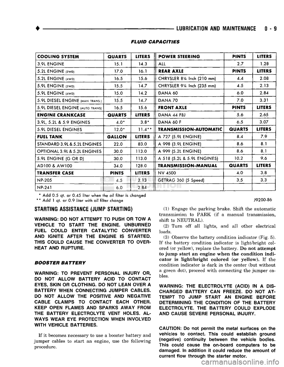
0 - 9 FLUID CAPACITIES
COOLING SYSTEM
QUARTS
LITERS
POWER STEERING PINTS
LITERS
3.9L ENGINE 15.1 14.3
ALL
2.7
1.28
5.2L ENGINE
(2WD)
17.0 16.1
REAR
AXLE
PINTS
LITERS
5.2L ENGINE
(4WD)
16.5 15.6
CHRYSLER
BVa
Inch
(210
mm) 4.4
2.08
5.9L ENGINE
(2WD)
15.5 14.7
CHRYSLER
9Va
Inch
(235
mm) 4.5
2.13
5.9L ENGINE
(4WD)
15.0 14.2
DANA
60 6.0
2.84
5.9L DIESEL ENGINE (MAN.TRANS.) 15.5 14.7
DANA
70 7.0
3.31
5.9L DIESEL ENGINE
(AUTO,
TRANS)
16.5 15.6
FRONT AXLE
PINTS
LITERS
ENGINE
CRANKCASE
QUARTS
LITERS
DANA
44
FBJ 5.6
2.65
3.9L,
5.2L & 5.9
ENGINES 4.0* 3.8*
DANA
60 F
6.5
3.07
5.9L DIESEL ENGINES 12.0*
11.4**
TRANSMISSION-AUTOMATIC
QUARTS
LITERS
FUEL TANK GALLON
LITERS
A
727 (5.9L
ENGINE) 8.4
7.9
STANDARD
3.9L & 5.2L ENGINES 22.0 83.0
A
998 (3.9L
ENGINE) 8.6
8.1
OPTIONAL 3.9L & 5.2L ENGINES 30.0 113.0
A
999 (5.2L
ENGINE) 8.6
8.1
5.9L ENGINE
{G
OR
D)
30.0 113.0
A
518 (5.2L & 5.9L
ENGINES) 10.2
9.6
AD 100
&
AW 100 34.0 128.0
TRANSMISSION-MANUAL
QUARTS
LITERS
TRANSFER
CASE
PINTS
LITERS
NV
4500
4.0
3.8
NP-205
4.5 2.13
GETRAG
360 (5
Speed)
3.5
3.3
NP-241
6.0
2.84
* Add
0.5 qt. or 0.45
liter
when
the oil filter
is
changed
*
*
Add
1 qt. or 0.9
liter
with
oil filter
change STARTING ASSISTANCE (JUMP STARTING)
WARNING:
DO NOT
ATTEMPT
TO
PUSH
OR
TOW
A
VEHICLE
TO
START
THE
ENGINE. UNBURNED FUEL COULD ENTER CATALYTIC CONVERTER
AND IGNITE AFTER
THE
ENGINE
IS
STARTED.
THIS COULD CAUSE
THE
CONVERTER
TO
OVER HEAT AND RUPTURE.
BOOSTER BATTERY
WARNING:
TO
PREVENT PERSONAL INJURY
OR,
DO
NOT
ALLOW BATTERY ACID
TO
CONTACT
EYES,
SKIN
OR
CLOTHING.
DO NOT
LEAN OVER
A
BATTERY WHEN CONNECTING JUMPER
CABLES.
DO
NOT
ALLOW
THE
POSITIVE
AND
NEGATIVE
CABLE
CLAMPS
TO
CONTACT EACH OTHER.
KEEP
OPEN FLAMES
AND
SPARKS
AWAY FROM
THE BATTERY ELECTROLYTE VENT HOLES.
AL
WAYS
WEAR
EYE
PROTECTION WHEN INVOLVED
WITH
VEHICLE BATTERIES.
If it becomes necessary to use a booster battery and
jumper cables to start an engine, use the following procedure.
J9200-86
(1) Engage the parking brake. Shift the automatic
transmission to PARK (if a manual transmission, shift to NEUTRAL).
(2) Turn off all lights, and all other electrical
loads.
(3)
Observe the battery condition indicator (Fig. 5).
If the battery condition indicator is light/bright col
ored (or yellow), replace the battery. Do not attempt
to jump start an engine when the condition indi
cator is light/bright colored (or yellow). If the
condition indicator is dark in the center (but without a green dot), proceed with connecting the jumper ca
bles.
WARNING:
THE
ELECTROLYTE (ACID)
IN A
DIS
CHARGED
BATTERY
CAN
FREEZE.
DO NOT AT
TEMPT
TO
JUMP START
AN
ENGINE BEFORE DETERMINING
THE
CONDITION
OF THE
BATTERY
ELECTROLYTE.
THE
BATTERY COULD EXPLODE
AND CAUSE SEVERE PERSONAL INJURY.
CAUTION:
Do not
permit
the
metal
surfaces
on the
vehicles
to
contact.
This
could
establish
ground
(negative)
continuity
between
the
vehicle
bodies.
This
could
cause
the
on-board
computers
to be
damaged.
In
addition
it
could
reduce
the
amount
of
current
flow
through
the
starter
motor.
Page 31 of 1502

0 - 12
LUBRICATION
AND
MAINTENANCE
• A vehicle equipped with SAE approved sling-type
towing equipment can be used (Fig. 10). However,
many vehicles are equipped with air dams, spoilers, and/or ground effect panels. In this case a wheel-lift
towing vehicle or a flat-bed hauling vehicle is recom mended (Fig. 10). If a flat bed device is used, the ap
proach angle should not exceed 15 degrees.
GROUND CLEARANCE The lifted wheels of the disabled vehicle should be
a minimum of 10 cm (4 in.) off the ground. Make
sure there is enough clearance at the opposite end.
This is critical when towing over rough terrain. If necessary, the rear ground clearance can be increased by removing the wheels from the lifted end
and then towing with the lifted end closer to the
ground. If the rear wheels are removed, secure the
brake drums. A 20 cm (8 in.) ground clearance must
be maintained between brake drums or rotors and the ground.
SAFETY PRECAUTIONS The following safety precautions must be consid
ered when preparing for and during a vehicle towing operation:
• Remove exhaust pipe tips that interfere with the
tow sling and crossbar • Padding should be placed between the tow sling/
crossbar and any painted surfaces
• If the vehicle is damaged, secure the loose and pro
truding parts
• Always use a safety chain system that is indepen dent of the lifting and towing equipment
• When placing tow hooks on the rear axle, position them so they do not damage the brake tubing or
hoses
• Do not allow any of the towing equipment to con
tact the fuel tank
• Do not tow the vehicle by connecting to the front
or rear shock absorbers
• The operator should not go under a vehicle while
it is lifted by the towing equipment. The vehicle
should first be supported by safety stands
• Do not allow passengers in a vehicle being towed
• Observe all state and local laws involving warning signals, night illumination, speed, etc.
• Do not exceed a towing speed of 48 km/h (30 mph)
• Avoid towing distances of more than 24 km (15
miles) whenever possible • Do not attach tow chains or a tow sling to a
bumper, the steering linkage, the universal joints, or a drive shaft
REAR-END RAISED TOWING It is recommended that the rear-end raised towing
method be used. Vehicles can be towed with the front
wheels on the ground for extended distances at speeds not exceeding 48 km/h (30 mph) (Fig. 11). (1) Attach the J-hooks around the axle shaft tubes
outboard of the rear springs. (2) Position and center the sling under and for
ward of the rear bumper. (3) Attach safety chains (with pads) at each end of
the rear bumper.
(4) Turn the ignition switch to the OFF position to
unlock the steering wheel. (5) Clamp the steering wheel with the front wheels
in the straight ahead position.
CAUTION:
Do not use the steering
column
lock
to
secure
front
wheel
in the straight-ahead
position.
(6) Shift the transmission to NEUTRAL.
POSITION CENTER BAR FORWARD
OF
BUMPER
-
/
J-HOOKS OUTBOARD
OF
SPRINGS
RN967A
Fig. 11 Rear-End
Raised
Towing
FRONT'END RAISED TOWING If a vehicle cannot be towed from the rear, the
front-end raised towing method normally can be
used (Fig. 12). (1) Center the sling with the bumper and position
it at the frame front crossmember.
CAUTION:
Use tow
chains
with
J-hooks
for
con
necting
to the
disabled
vehicle's
lower
suspension
arms.
Never use
T-hooks.
(2) Route the J-hooks and tow chains over the
steering linkage outboard of the coil spring.
(3) Attach the J-hooks to the outer end of the
lower suspension arms.
(4) Raise the vehicle.
(5.) Attach the safety chains to the disabled vehicle
at the frame rails.
Vehicles equipped with a MANUAL TRANSMIS
SION can be towed with the rear wheels on the
Page 42 of 1502
•
LUBRICATION
AND
MAINTENANCE
0 - 23 GEAR SHIFTER BOOTS
Inspect the shifter boots periodically for stone and
heat damage. Replace, if necessary.
SEVERE DRIVING CONDITIONS The interval between the transmission drain and
refill maintenance should be decreased to:
• NV4500 manual transmission—every 29 000 km (18,000 miles)
• Automatic transmission—every 19 000 km (12,000
miles)
A severe driving condition includes:
• Extended operation with heavy cargo loads
• Driving in deep mud or snow
• Off-road operation (4WD)
• Trailer towing
• Operation as a commercial vehicle
• Snow plowing
MANUAL TRANSMISSIONS
INSPECTION/LUBE
OIL
LEVEL
The transmission should be checked for leaks when
other service is necessary under the vehicle. To check
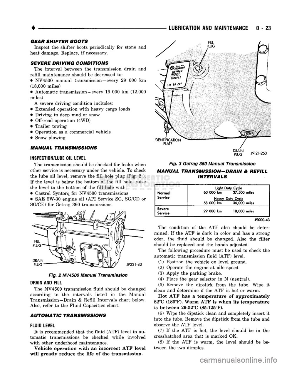
the lube oil level, remove the fill hole plug (Fig. 2 ). If the level is below the bottom of the fill hole, raise
the level to the bottom of the fill hole with:
• Castrol Syntorq for NV4500 transmissions
• SAE 5W-30 engine oil (API Service SG, SG/CD or
SG/CE) for Getrag 360 transmissions.
Fig.
2 NV4500 Manual
Transmission
DRAIN
AND
FILL
The NV4500 transmission fluid should be changed
according to the intervals listed in the Manual
Transmission—Drain & Refill Intervals chart below.
Also,
refer to the Fluid Capacities chart.
AUTOMATIC TRANSMISSIONS
FLUID
LEWEL
It is recommended that the fluid (ATF) level in au
tomatic transmissions be checked while involved
with other underhood maintenance.
Vehicle operation with an incorrect ATF level
will greatly reduce the life of the transmission.
Fig.
3 Getrag 360 Manual
Transmission
MANUAL TRANSMISSION-DRAIN & REFILL INTERVALS
Normal
Service
Light
Duty
Cycle
60 000
km
37,500
miles
Heavy
Duty
Cycle
58 000
km
36,000
miles
Severe
Service
29 000
km
18,000
miles
J9000-43
The condition of the ATF also should be deter
mined. If the ATF is dark in color and has a strong odor, the fluid should be changed. Also the filter should be replaced and the bands adjusted.
The following procedure must be used to check the
automatic transmission fluid (ATF) level.
(1) Position the vehicle on level ground.
(2) Operate the engine at idle speed.
(3) Apply the parking brake.
(4) Place the gear selector in N (neutral).
(5) Remove the dipstick from the tube. Wipe it
clean and determine if the ATF is hot or warm.
Hot ATF has a temperature of approximately
82°C (180°F). Warm ATF is when its temperature
is between 29-52°C (85-125°F). (6) Wipe the dipstick clean and completely insert it
into the tube. Remove the dipstick from the tube and
observe the ATF level.
(7) If the ATF is hot, the level should be in the
crosshatched area that is marked OK.
(8) If the ATF is warm, the level should be be
tween the two dimples.
Page 81 of 1502
2 - 28
FRONT
SUSPENSION
AND
AXLE
DISCONNECT
AXLE/SHIFT
MOTOR
DIAGNOSIS
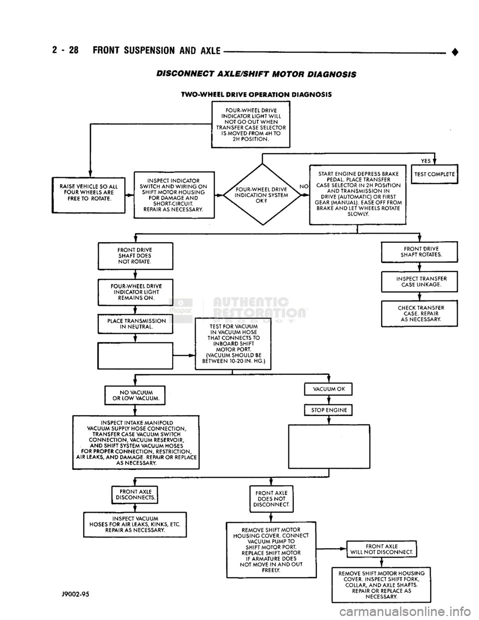
TWO-WHEEL DRIVE
OPERATION
DIAGNOSIS
FOUR-WHEEL DRIVE
INDICATOR
LIGHT
WILL NOT GO OUT WHEN
TRANSFER CASE SELECTOR
IS
MOVED FROM 4H TO 2H POSITION.
RAISE
VEHICLE SO ALL FOUR WHEELS ARE
FREE
TO ROTATE. INSPECT INDICATOR
SWITCH AND WIRING ON SHIFT MOTOR HOUSING FOR DAMAGE AND SHORT-CIRCUIT.
REPAIR
AS NECESSARY.
YES
i
START ENGINE DEPRESS BRAKE
PEDAL.
PLACE TRANSFER
CASE
SELECTOR IN 2H POSITION AND TRANSMISSION IN
DRIVE
(AUTOMATIC)
OR FIRST
GEAR
(MANUAL). EASE OFF FROM
BRAKE
AND LET WHEELS ROTATE SLOWLY. TEST COMPLETE
FRONT DRIVE SHAFT DOES
NOT ROTATE. FRONT DRIVE
SHAFT ROTATES.
FOUR-WHEEL DRIVE INDICATOR
LIGHT
REMAINS
ON. INSPECT TRANSFER
CASE
LINKAGE.
PLACE
TRANSMISSION IN NEUTRAL. TEST FOR VACUUM
IN VACUUM HOSE
THAT
CONNECTS TO INBOARD SHIFT MOTOR PORT.
(VACUUM SHOULD BE
BETWEEN 10-20 IN. HG.)
CHECK
TRANSFER
CASE.
REPAIR
AS
NECESSARY.
NO VACUUM
OR LOW VACUUM. VACUUM OK
INSPECT INTAKE MANIFOLD
VACUUM SUPPLY HOSE CONNECTION,
TRANSFER CASE VACUUM SWITCH
CONNECTION, VACUUM RESERVOIR, AND SHIFT SYSTEM VACUUM HOSES
FOR PROPER CONNECTION, RESTRICTION,
AIR LEAKS, AND DAMAGE. REPAIR OR REPLACE
AS
NECESSARY. STOP ENGINE
—r~
FRONT AXLE
DISCONNECTS.
INSPECT VACUUM
HOSES
FOR AIR LEAKS, KINKS, ETC.
REPAIR
AS NECESSARY. FRONT AXLE
DOES
NOT
DISCONNECT.
REMOVE SHIFT MOTOR
HOUSING COVER. CONNECT VACUUM PUMP TO
SHIFT MOTOR PORT.
REPLACE
SHIFT MOTOR
IF ARMATURE DOES
NOT MOVE IN AND OUT FREELY. FRONT AXLE
WILL NOT DISCONNECT.
J9002-95
REMOVE SHIFT MOTOR HOUSING
COVER. INSPECT SHIFT FORK, COLLAR, AND AXLE SHAFTS.
REPAIR
OR REPLACE AS
NECESSARY
Page 82 of 1502
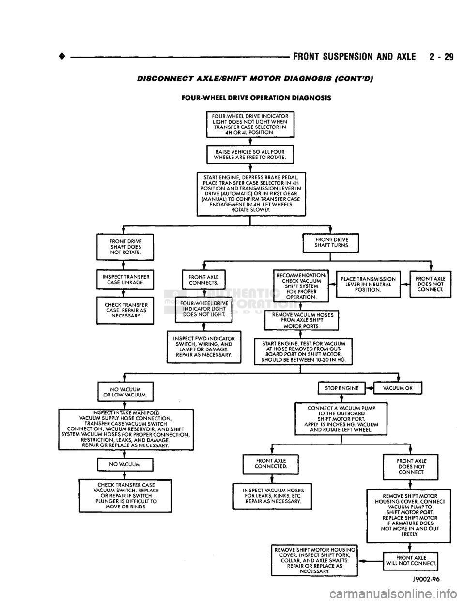
FRONT
SUSPENSION AND
AXLE
2 - 29
DISCONNECT AXLE/SHIFT MOTOR DIAGNOSIS
(CONT'D)
FOUR-WHEEL
DRIVE
OPERATION
DIAGNOSIS
FOUR-WHEEL DRIVE INDICATOR
LIGHT
DOES NOT
LIGHT
WHEN TRANSFER CASE SELECTOR IN 4H OR 4L POSITION.
RAISE
VEHICLE SO ALL FOUR
WHEELS ARE FREE TO ROTATE.
START ENGINE, DEPRESS BRAKE PEDAL.
PLACE
TRANSFER CASE SELECTOR IN 4H
POSITION AND TRANSMISSION LEVER IN DRIVE
(AUTOMATIC)
OR IN FIRST GEAR
(MANUAL) TO CONFIRM TRANSFER CASE ENGAGEMENT IN 4H. LET WHEELS ROTATE SLOWLY.
FRONT DRIVE SHAFT DOES
NOT ROTATE. FRONT DRIVE
SHAFT TURNS.
INSPECT TRANSFER
CASE
LINKAGE.
CHECK
TRANSFER
CASE.
REPAIR AS
NECESSARY.
FRONT AXLE
CONNECTS.
FOUR-WHEEL DRIVE INDICATOR
LIGHT
DOES
NOT LIGHT.
INSPECT FWD INDICATOR SWITCH, WIRING, AND
LAMP FOR DAMAGE.
REPAIR
AS NECESSARY. RECOMMENDATION:
CHECK
VACUUM SHIFT SYSTEM FOR PROPER
OPERATION.
PLACE
TRANSMISSION
LEVER IN NEUTRAL POSITION. FRONT AXLE
DOES
NOT
CONNECT.
REMOVE VACUUM HOSES FROM AXLE SHIFT MOTOR PORTS.
START ENGINE. TEST FOR VACUUM AT HOSE REMOVED FROM
OUT
BOARD
PORT ON SHIFT MOTOR,
SHOULD BE BETWEEN 10-20 IN HG.
NO VACUUM
OR LOW VACUUM. STOP ENGINE
H VACUUM OK
INSPECT INTAKE MANIFOLD
VACUUM SUPPLY HOSE CONNECTION, TRANSFER CASE VACUUM SWITCH
CONNECTION, VACUUM RESERVOIR, AND SHIFT
SYSTEM VACUUM HOSES FOR PROPER CONNECTION, RESTRICTION, LEAKS, AND DAMAGE.
REPAIR
OR REPLACE AS NECESSARY. CONNECT A VACUUM PUMP
TO THE OUTBOARD
SHIFT MOTOR PORT.
APPLY 15 INCHES HG. VACUUM AND ROTATE LEFT WHEEL.
NO VACUUM FRONT AXLE
CONNECTED.
CHECK
TRANSFER CASE
VACUUM SWITCH. REPLACE OR REPAIR IF SWITCH
PLUNGER IS DIFFICULT TO MOVE OR BINDS. FRONT AXLE
DOES
NOT
CONNECT.
INSPECT VACUUM HOSES FOR LEAKS, KINKS, ETC.
REPAIR
AS NECESSARY. REMOVE SHIFT MOTOR
HOUSING COVER. CONNECT VACUUM PUMP TO
SHIFT MOTOR PORT.
REPLACE
SHIFT MOTOR
IF ARMATURE DOES
NOT MOVE IN AND OUT FREELY. REMOVE SHIFT MOTOR HOUSING
COVER. INSPECT SHIFT FORK, COLLAR, AND AXLE SHAFTS.
REPAIR
OR REPLACE AS
NECESSARY.
*
REMOVE SHIFT MOTOR HOUSING
COVER. INSPECT SHIFT FORK, COLLAR, AND AXLE SHAFTS.
REPAIR
OR REPLACE AS
NECESSARY.
FRONT AXLE
WILL NOT CONNECT.
REMOVE SHIFT MOTOR HOUSING
COVER. INSPECT SHIFT FORK, COLLAR, AND AXLE SHAFTS.
REPAIR
OR REPLACE AS
NECESSARY.
FRONT AXLE
WILL NOT CONNECT.
REMOVE SHIFT MOTOR HOUSING
COVER. INSPECT SHIFT FORK, COLLAR, AND AXLE SHAFTS.
REPAIR
OR REPLACE AS
NECESSARY.
J9002-96
Page 155 of 1502
3
- 28
REAR
SUSPENSION
AND
AXLE
•
SURE-GRIP
DIFFERENTIAL
SERVICE
GENERAL
INFORMATION
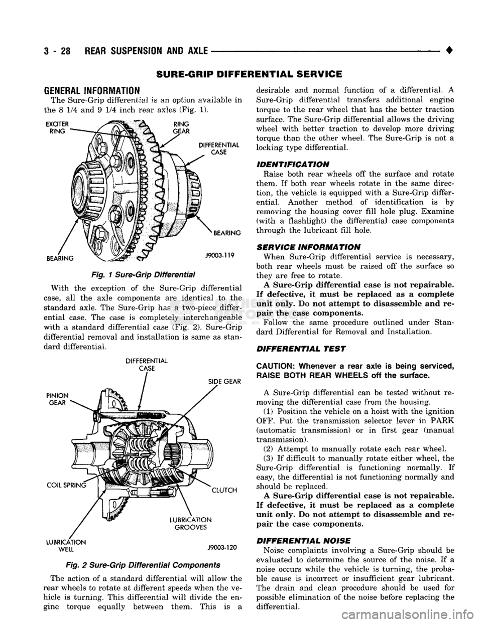
The Sure-Grip differential
is an
option available
in
the
8 1/4 and 9 1/4
inch rear axles
(Fig. 1).
EXCITER
RING RING
GEAR
DIFFERENTIAL
CASE
BEARING BEARING
J9003-119
Fig.
1
Sure-Grip
Differential
With
the
exception
of the
Sure-Grip differential
case,
all the
axle components
are
identical
to the
standard axle.
The
Sure-Grip
has a
two-piece differ
ential case.
The
case
is
completely interchangeable
with
a
standard differential case
(Fig. 2).
Sure-Grip differential removal
and
installation
is
same
as
stan
dard differential.
DIFFERENTIAL
CASE
PINION
GEAR
COIL SPRING LUBRICATION
WELL
SIDE
GEAR
CLUTCH
LUBRICATION
GROOVES
J9003-120
Fig.
2
Sure-Grip
Differential
Components
The action
of a
standard differential will allow
the
rear wheels
to
rotate
at
different speeds when
the ve
hicle
is
turning. This differential will divide
the en
gine torque equally between them. This
is a
desirable
and
normal function
of a
differential.
A
Sure-Grip differential transfers additional engine
torque
to the
rear wheel that
has the
better traction surface.
The
Sure-Grip differential allows
the
driving
wheel with better traction
to
develop more driving
torque than
the
other wheel.
The
Sure-Grip
is not a
locking type differential.
IDENTIFICATION Raise both rear wheels
off the
surface
and
rotate
them.
If
both rear wheels rotate
in the
same direc
tion,
the
vehicle
is
equipped with
a
Sure-Grip differ ential. Another method
of
identification
is by
removing
the
housing cover fill hole plug. Examine (with
a
flashlight)
the
differential case components
through
the
lubricant fill hole.
SERVICE INFORMATION When Sure-Grip differential service
is
necessary,
both rear wheels must
be
raised
off the
surface
so
they
are
free
to
rotate.
A Sure-Grip differential case
is not
repairable.
If defective,
it
must
be
replaced
as a
complete
unit only.
Do not
attempt
to
disassemble
and re
pair
the
case components.
Follow
the
same procedure outlined under Stan
dard Differential
for
Removal
and
Installation.
DIFFERENTIAL TEST
CAUTION:
Whenever
a
rear axle
is
being
serviced,
RAISE
BOTH
REAR
WHEELS
off the
surface.
A Sure-Grip differential
can be
tested without
re
moving
the
differential case from
the
housing.
(1) Position
the
vehicle
on a
hoist with
the
ignition
OFF.
Put the
transmission selector lever
in
PARK
(automatic transmission)
or in
first gear (manual
transmission).
(2) Attempt
to
manually rotate each rear wheel.
(3)
If
difficult
to
manually rotate either wheel,
the
Sure-Grip differential
is
functioning normally.
If
easy,
the
differential
is not
functioning normally
and
should
be
replaced.
A Sure-Grip differential case
is not
repairable.
If defective,
it
must
be
replaced
as a
complete
unit only.
Do not
attempt
to
disassemble
and re
pair
the
case components.
DIFFERENTIAL NOISE Noise complaints involving
a
Sure-Grip should
be
evaluated
to
determine
the
source
of the
noise.
If a
noise occurs while
the
vehicle
is
turning,
the
proba
ble cause
is
incorrect
or
insufficient gear lubricant. The drain
and
clean procedure should
be
used
for
possible elimination
of the
noise before replacing
the
differential.
Page 330 of 1502
•
ELECTRICAL
8A - 9
ENGINE STARTER MOTOR TEST PROCEDURES
GENERAL INFORMATION
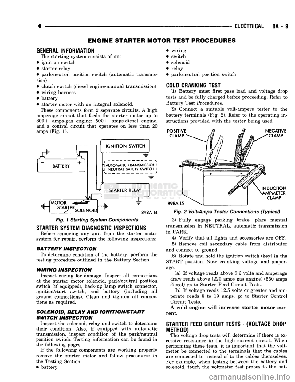
The starting system consists of an:
• ignition switch
• starter relay
• park/neutral position switch (automatic transmis sion)
• clutch switch (diesel engine-manual transmission)
• wiring harness
• battery
• starter motor with an integral solenoid. These components form 2 separate circuits. A high
amperage circuit that feeds the starter motor up to
300+ amps-gas engine; 500+ amps-diesel engine,
and a control circuit that operates on less than 20
amps (Fig. 1).
a.
BATTERY +
1
IGNITION
SWITCH 1 AUTOMATIC TRANSMISSION
•
J
NEUTRAL SAFETY SWITCH
I 4-
"JL"
MOTOR
m, ...
STA3-TERSOLENO,Dnlh
STARTER RELAY
1"
898A-14
Fig.
1 Starting
System
Components
STARTER SYSTEM DIAGNOSTIC INSPECTIONS
Before removing any unit from the starter motor
system for repair, perform the following inspections:
BATTERY
INSPECTION
To determine condition of the battery, perform the
testing procedure outlined in the Battery Section.
WIRING INSPECTION
Inspect wiring for damage. Inspect all connections
at the starter motor solenoid, park/neutral position
switch (if equipped), back-up lamp switch connector,
ignition/start switch, and battery (including all
ground connections). Clean and tighten all connec
tions as required.
SOLENOID, RELAY
AND
IGNITION/START
SWITCH
INSPECTION
Inspect the solenoid, relay and switch to determine
their condition. Also, if equipped with automatic
transmission, inspect condition of the park/neutral position switch. Testing information can be found in
the following pages.
If the following components are working properly
remove the starter motor and follow procedures in
the Testing Section. • battery wiring
switch
solenoid
relay
park/neutral position switch
COLD CRANKING TEST
(1) Battery must first pass load and voltage drop
tests and be fully charged before proceeding. Refer to Battery Test Procedures. (2) Connect a suitable volt-ampere tester to the
battery terminals (Fig. 2). Refer to the operating in structions provided with the tester being used.
POSITIVE
CLAMP
898A-15
NEGATIVE
CLAMP
INDUCTION
AMPMETER
CLAMP
Fig.
2
Volt-Amps
Tester
Connections
(Typical)
(3) Fully engage parking brake, place manual
transmission in NEUTRAL, automatic transmission
in PARK. (4) Verify that all lights and accessories are OFF. (5) Remove coil secondary cable from distributor
and connect to ground.
(6) Rotate and hold the ignition switch (key) in the
START position. Note cranking voltage and amper
age.
(a) If voltage reads above 9.6 volts and amperage
draw reads above (220 amps gas engine) (550 amps
diesel) go to Starter Feed Circuit Tests. (b) If voltage reads 12.5 volts or greater and am-
perate reads 0 to 10 amps, go to Starter Control Circuit Tests.
A cold engine will increase starter motor cur
rent.
STARTER
FEED
CIRCUIT TESTS
-
(W0LTAGE
DROP
METHOD)
The voltage drop tests will determine if there is ex
cessive resistance in the high current circuit. When
performing these tests, it is important that the volt meter be connected to the terminals that the cables are connected to instead of to the cables themselves.
For example, when testing between the battery and
solenoid, touch the voltmeter test probes to the bat-