1993 DODGE TRUCK clock
[x] Cancel search: clockPage 316 of 1502
•
COOLING
SYSTEM
7 - 45 (3) Rotate socket/wrench counterclockwise. Install
belt over tensioner pulley. Let tensioner rotate back into place. Remove wrench. Be sure belt is properly
seated on all pulleys.
5«9L
DIESEL ENGINE
REMOVAL
Drive belts on diesel engines are equipped with a
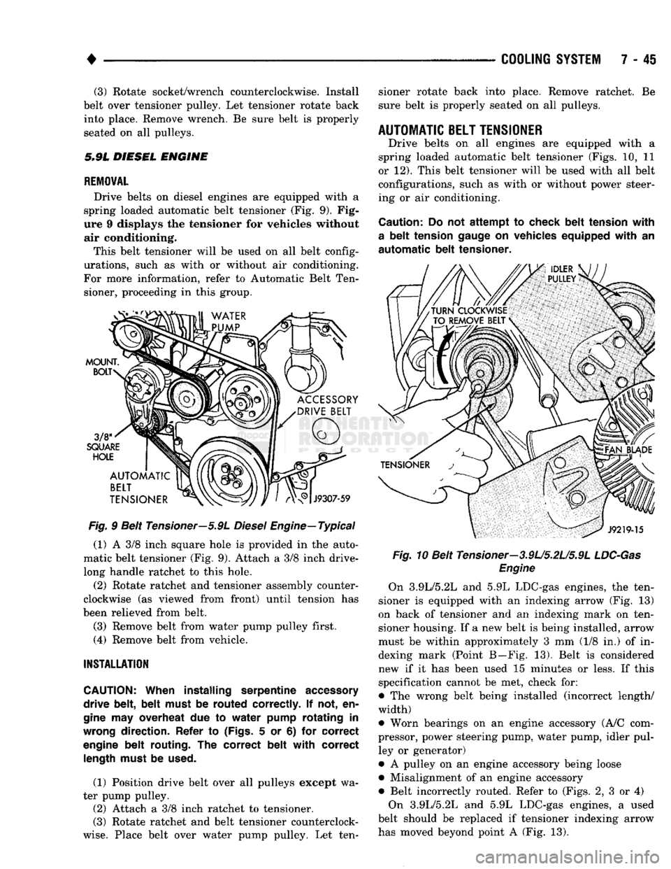
spring loaded automatic belt tensioner (Fig. 9). Fig
ure 9 displays the tensioner for vehicles without air conditioning.
This belt tensioner will be used on all belt config
urations, such as with or without air conditioning.
For more information, refer to Automatic Belt Ten sioner, proceeding in this group.
Fig.
9 Belt Tensioner—5.9L
Diesel
Engine—Typical
(1) A 3/8 inch square hole is provided in the auto
matic belt tensioner (Fig. 9). Attach a 3/8 inch drive-
long handle ratchet to this hole.
(2) Rotate ratchet and tensioner assembly counter
clockwise (as viewed from front) until tension has
been relieved from belt.
(3) Remove belt from water pump pulley first.
(4) Remove belt from vehicle.
INSTALLATION
CAUTION:
When installing serpentine
accessory
drive belt, belt must
be
routed correctly.
If not, en
gine
may
overheat
due to
water pump rotating
in
wrong
direction. Refer
to
(Figs.
5 or 6) for
correct
engine
belt routing.
The
correct belt with correct
length
must
be
used.
(1) Position drive belt over all pulleys except wa
ter pump pulley. (2) Attach a 3/8 inch ratchet to tensioner.
(3) Rotate ratchet and belt tensioner counterclock
wise.
Place belt over water pump pulley. Let ten sioner rotate back into place. Remove ratchet. Be
sure belt is properly seated on all pulleys.
AUTOMATIC
BELT
TENSIONER
Drive belts on all engines are equipped with a
spring loaded automatic belt tensioner (Figs. 10, 11
or 12). This belt tensioner will be used with all belt configurations, such as with or without power steer
ing or air conditioning.
Caution:
Do not
attempt
to
check belt tension with
a
belt tension
gauge
on
vehicles equipped with
an
automatic
belt tensioner. Fig.
10 Belt Tensioner—3.9U5.2U5.9L
LDC-Gas
Engine
On 3.9L/5.2L and 5.9L LDC-gas engines, the ten
sioner is equipped with an indexing arrow (Fig. 13)
on back of tensioner and an indexing mark on ten
sioner housing. If a new belt is being installed, arrow
must be within approximately 3 mm (1/8 in.) of in dexing mark (Point B—Fig. 13). Belt is considered
new if it has been used 15 minutes or less. If this
specification cannot be met, check for:
• The wrong belt being installed (incorrect length/
width)
• Worn bearings on an engine accessory (A/C com
pressor, power steering pump, water pump, idler pul ley or generator)
• A pulley on an engine accessory being loose
• Misalignment of an engine accessory
• Belt incorrectly routed. Refer to (Figs. 2, 3 or 4) On 3.9L/5.2L and 5.9L LDC-gas engines, a used
belt should be replaced if tensioner indexing arrow
has moved beyond point A (Fig. 13).
Page 325 of 1502
8A
- 4
ELECTRICAL
•
IGNITION
OFF
DRAW
(IOD)
Ignition off draw refers to power being drained
from the battery with the ignition turned off. A nor
mal vehicle electrical system will draw from 5 to 20
milliamps. A vehicle that has not been operated for
an extended period of time (approximately 20 days)
may discharge the battery to an inadequate level.
Battery drain should not exceed approximately 20
MA (20 milliamps = 0.020 amps). The 20 MA are needed to supply PCM memory,
digital clock memory, and ETR (electronically tuned
radio) memory. Excessive battery drain is caused by items left
turned on, internally shorted generator, or intermit
tent short in wiring.
If the IOD is excessive (over 20 milliamperes), the
defect must be found and corrected before replacing a
battery. In most cases the battery can be charged and returned to service.
TEST PROCEDURE Testing for higher amperage IOD must be per
formed first to prevent damage to most milliamp
meters.
Verify that all electrical accessories are OFF. Turn
off all lights, remove ignition key, and close all
doors.
If the vehicle is equipped with electronic acces
sories (illuminated entry, high line radio), allow the
systems to automatically shut off (time out), up to 3
minutes.
(1) After determining that the underhood lamp is
operating properly then disconnect bulb. (2) Disconnect negative cable from battery.
(3) Connect a typical 12 volt test light (low watt
age bulb) between the negative cable clamp and the
battery negative terminal. The test light may light brightly for up to 3 min
utes or may not light at all (depending on the elec
trical equipment). The term brightly being used
throughout the following tests, implies the bright ness of the test light will be the same as if it were
connected across the battery.
The test light must be securely clamped to the neg
ative cable and battery terminal. If the test light be
comes disconnected during any of the IOD test, the electronic timer function will be activated and all
tests must be repeated.
(4) After 3 minutes, the test light should turn OFF
or be DIMLY lit (depending on the electrical equip
ment).
If the test light remains brightly lit do not
disconnect it. Remove each fuse or circuit breaker (refer to Group 8 - Wiring Diagrams) until test light
is either OFF or DIMLY lit. This will eliminate the
higher amperage draw.
If test light is still bright after disconnecting each
fuse and circuit breaker, disconnect the wiring har ness from the generator. Refer to Generator Testing
in this group. Do not disconnect the test light. After higher amperage IOD has been corrected, low
amperage IOD may be checked.
It is now safe to install milliamp meter to check for
low amperage IOD.
(5) With test light still connected, securely clamp
an ammeter between battery negative terminal and
negative battery cable.
If the test light or the milliamp meter circuit is
broken the various timer circuits will start. Do
not open any doors or turn on any electrical ac cessories with the test light disconnected or the
meter may be damaged.
(6) Disconnect test light. The current draw should
not exceed 0.020 amp. If it exceeds 20 milliamps iso
late each circuit by removing circuit breakers and
fuses.
The meter reading drops once the high current
problem is found. Repair this section of the circuit,
whether it is a wiring short or component failure.
BATTERY
OPEN CIRCUIT VOLTAGE TEST
A battery voltage (no load) test will indicate the
state of charge of a battery that will pass the Battery
Load Test described in this section. Before proceed
ing with this test or the Battery Load Test the
battery must be completely charged as de scribed in Battery Charging in this section. If a battery has a no load voltage reading of 12.4
volts or greater but will not endure a load test, it is
defective and should be replaced. Refer to Group 8B,
Battery/Starter Service for instructions. To test bat
tery no load voltage, perform the following operation: (1) Before measuring open circuit voltage, the sur
face charge must be removed from plates. Turn head lights on for 15 seconds then allow up to 5 minutes
for voltage to stabilize. (2) Remove both battery cables, negative first.
(3) Using a voltmeter connected to the battery
posts,
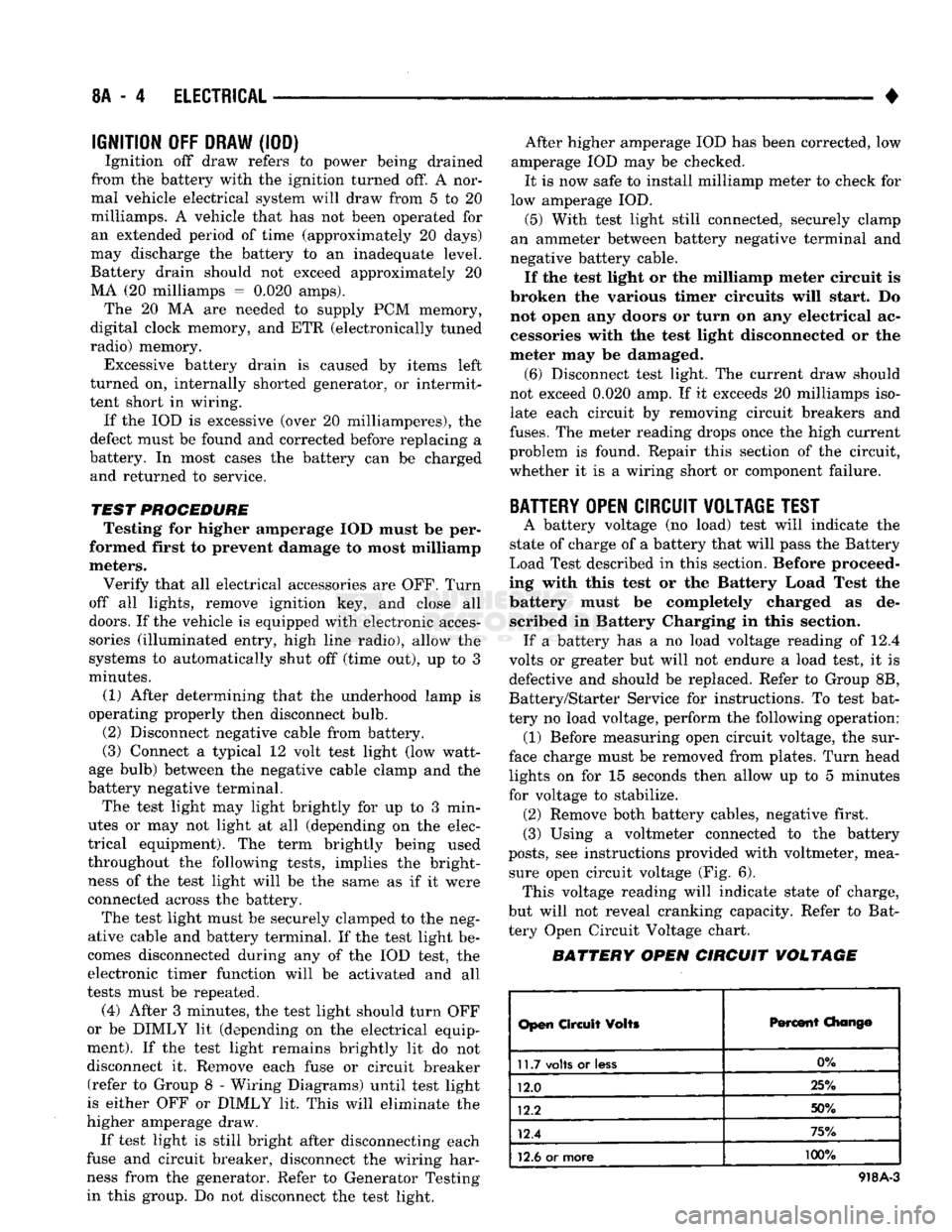
see instructions provided with voltmeter, mea sure open circuit voltage (Fig. 6). This voltage reading will indicate state of charge,
but will not reveal cranking capacity. Refer to Bat
tery Open Circuit Voltage chart.
BATTERY OPEN CIRCUIT VOLTAGE
Open
Circuit
Volts
Percent
Chang©
11.7
volts
or
less
0%
12.0 25%
12.2 50%
12.4 75%
12.6
or more 100%
918A-3
Page 347 of 1502
8B
- 6
BATTERY/STARTER/GENERATOR
SERVICE
•
GENERATOR SERVICE
CONTENTS
page
GENERATOR
REPLACEMENT-
DIESEL
ENGINE
8
GENERAL
INFORMATION
6
GENERAL
INFORMATION This section will cover generator removal
and in
stallation.
The
generator
is not
serviceable. Informa
tion covering on-vehicle testing
can be
found
in
Group
8A -
Battery/Starting/Charging/System Diag
nostics. The standard equipment generator
on the D and W
bodies
is the 75 amp
generator.
The
Ramcharger
is
equipped with
the 90 amp
generator. When
a
vehicle
is equipped with
a
heavy duty package
or
diesel
en
gine,
a 120 amp
generator
is
used.
GENERATOR
REPLACEMENT
-3.9L/5.2L/5.9L-LDC
GAS
ENGINE
Drive belts
on
these engines
are
equipped with
a
spring loaded automatic belt tensioner
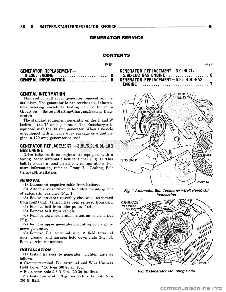
(Fig. 1).
This
belt tensioner
is
used
on all
belt configurations.
For
more information, refer
to
Group
7 -
Cooling, Belt
Removal/Installation.
REMOVAL
(1) Disconnect negative cable from battery.
(2) Attach
a
socket/wrench
to
pulley mounting bolt
of automatic tensioner
(Fig. 1).
(3) Rotate tensioner assembly clockwise
(as
viewed
from front) until tension
has
been relieved from belt. (4) Remove belt from idler pulley first.
(5) Remove belt from vehicle.
(6)
Remove lower generator mounting bolt
and nut
(Fig.
2).
(7) Remove upper generator mounting bolt
and re
move generator.
(8) Remove
B+
terminal
nut, 2
field terminal
nuts,
ground,
and
harness hold down nuts
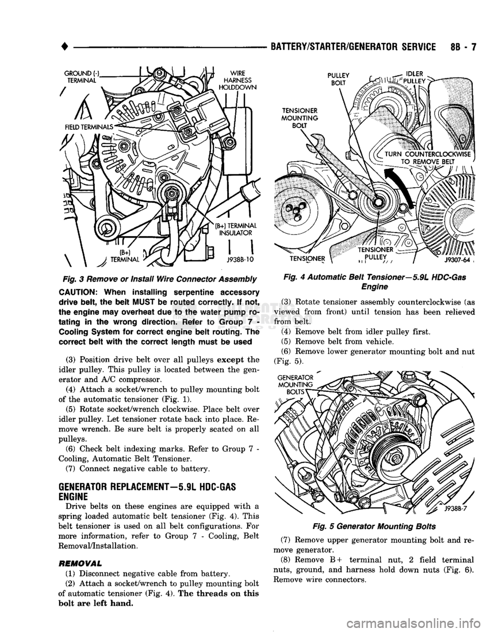
(Fig. 3).
Remove wire connectors.
INSTALLATION
(1) Install harness
to
generator. Tighten nuts
as
follows:
• Ground terminal,
B+
terminal
and
Wire Harness Hold Down
7-10 N*m
(60-90
in.
lbs.).
• Field terminals
2.5-3 N-m
(20-30
in.
lbs.). (2) Install generator. Tighten both bolts
to 41 N»m
(30
ft.
lbs.).
page
GENERATOR
REPLACEMENT—3.9L/5.2L/
5.9L-LDC
GAS
ENGINE
6
GENERATOR
REPLACEMENT—5.9L
HDC-GAS
ENGINE
7
Fig.
1 Automatic Belt Tensioner—Belt
Removal/
Installation
Fig.
2
Generator
Mounting
Bolts
Page 348 of 1502
•
Fig.
3
Remove
or install
Wire
Connector
Assembly
CAUTION:
When
installing
serpentine
accessory
drive
belt,
the
belt
MUST
be
routed
correctly.
If not,
the engine may overheat due to the
water
pump ro
tating
in the wrong
direction.
Refer to Group 7 -
Cooling
System
for
correct
engine
belt
routing.
The
correct
belt
with
the
correct
length
must be
used
(3) Position drive belt over all pulleys except the
idler pulley. This pulley is located between the gen
erator and A/C compressor.
(4) Attach a socket/wrench to pulley mounting bolt
of the automatic tensioner (Fig. 1).
(5)
Rotate socket/wrench clockwise. Place belt over
idler pulley. Let tensioner rotate back into place. Re
move wrench. Be sure belt is properly seated on all
pulleys.
(6) Check belt indexing marks. Refer to Group 7 -
Cooling, Automatic Belt Tensioner.
(7) Connect negative cable to battery.
GENERATOR
REPLACEMENT—5.9L
HDC-GAS
ENGINE
Drive belts on these engines are equipped with a
spring loaded automatic belt tensioner (Fig. 4). This
belt tensioner is used on all belt configurations. For more information, refer to Group 7 - Cooling, Belt
Removal/Installation.
REMOVAL
(1) Disconnect negative cable from battery.
(2) Attach a socket/wrench to pulley mounting bolt
of automatic tensioner (Fig. 4). The threads on this
bolt are left hand.
BATTERY/STARTER/GENERATOR
SERVICE
8B - 7
Fig.
4 Automatic Belt Tensioner—5.9L
HDC-Gas
Engine
(3) Rotate tensioner assembly counterclockwise (as
viewed from front) until tension has been relieved
from belt.
(4) Remove belt from idler pulley first.
(5) Remove belt from vehicle.
(6) Remove lower generator mounting bolt and nut
(Fig. 5).
Fig.
5 Generator
Mounting
Bolts
(7) Remove upper generator mounting bolt and re
move generator.
(8) Remove B+ terminal nut, 2 field terminal
nuts,
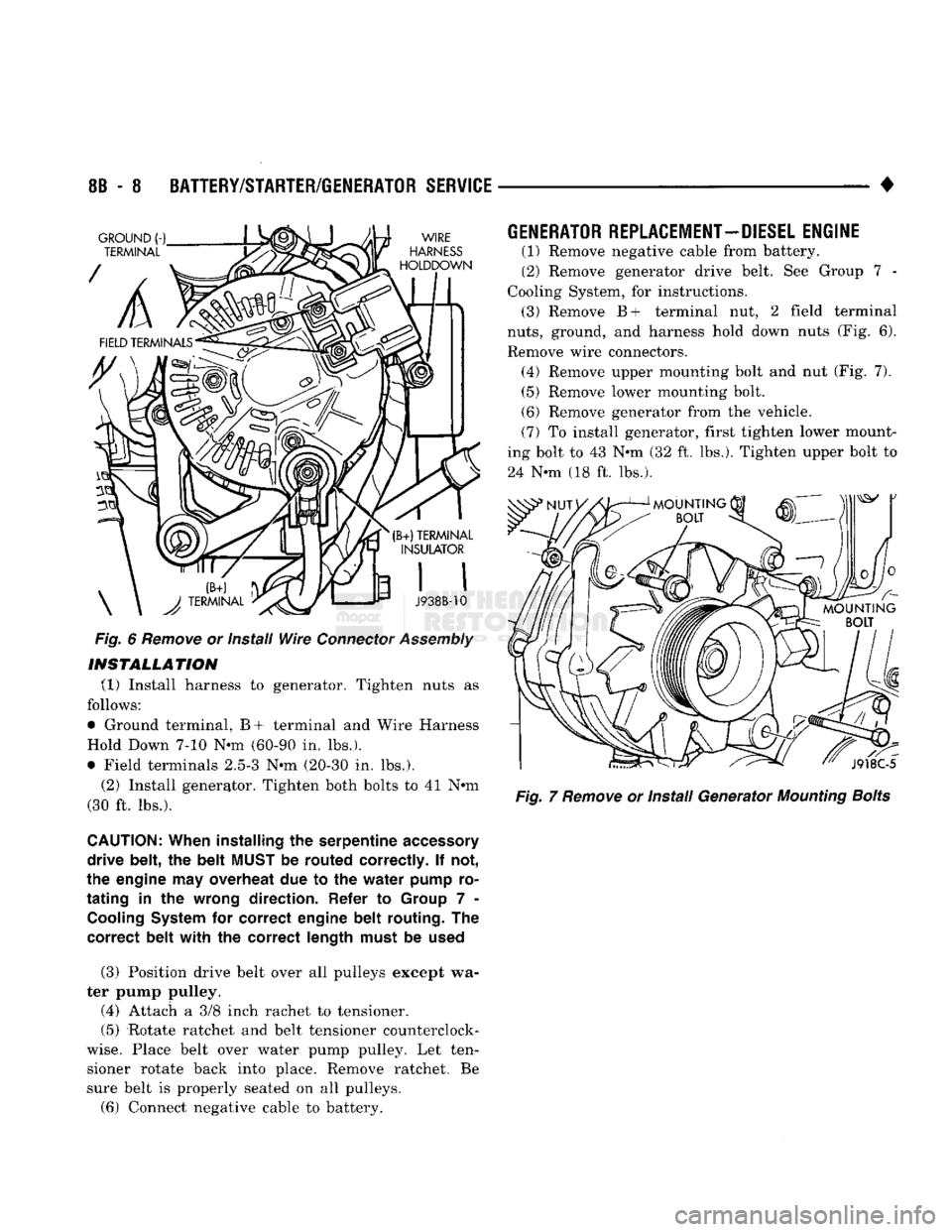
ground, and harness hold down nuts (Fig. 6).
Remove wire connectors.
Page 349 of 1502
8B
- 8
BATTERY/STARTER/GENERATOR
SERVICE
•
Fig.
6
Remove
or Install
Wire
Connector
Assembly
INSTALLATION
(1) Install harness to generator. Tighten nuts as
follows:
• Ground terminal, B+ terminal and Wire Harness
Hold Down 7-10 Nun (60-90 in. lbs.).
• Field terminals 2.5-3 Nun (20-30 in. lbs.).
(2) Install generator. Tighten both bolts to 41 Nun
(30 ft. lbs.).
CAUTION:
When
installing
the
serpentine
accessory
drive
belt,
the
belt
MUST
be
routed
correctly.
If not,
the
engine
may
overheat
due to the
water
pump
ro
tating
in the
wrong
direction.
Refer
to
Group
7 -
Cooling
System
for
correct
engine
belt
routing.
The
correct
belt
with
the
correct
length
must
be
used
(3) Position drive belt over all pulleys except wa
ter pump pulley.
(4) Attach a 3/8 inch rachet to tensioner.
(5) Rotate ratchet and belt tensioner counterclock
wise.
Place belt over water pump pulley. Let ten sioner rotate back into place. Remove ratchet. Be
sure belt is properly seated on all pulleys.
(6) Connect negative cable to battery.
GENERATOR
REPLACEMENT—DIESEL
ENGINE
(1) Remove negative cable from battery.
(2) Remove generator drive belt. See Group 7 -
Cooling System, for instructions. (3) Remove B+ terminal nut, 2 field terminal
nuts,
ground, and harness hold down nuts (Fig. 6).
Remove wire connectors. (4) Remove upper mounting bolt and nut (Fig. 7). (5) Remove lower mounting bolt.
(6) Remove generator from the vehicle.
(7) To install generator, first tighten lower mount
ing bolt to 43 Nun (32 ft. lbs.). Tighten upper bolt to
24 Nun (18 ft. lbs.).
Fig.
7
Remove
or Install Generator
Mounting
Bolts
Page 371 of 1502
8D
- 20
IGNITION
SYSTEMS
•
ENGINE
COOLANT
TEMPERATURE
SENSOR
WARNING: HOT, PRESSURIZED COOLANT CAN CAUSE INJURY BY SCALDING. COOLING SYSTEM MUST BE PARTIALLY DRAINED BEFORE REMOV
ING THE COOLANT TEMPERATURE SENSOR. RE
FER TO GROUP 7, COOLING.
REMOVAL
(1) Partially drain cooling system. Refer to Group
7, Cooling.
(2)
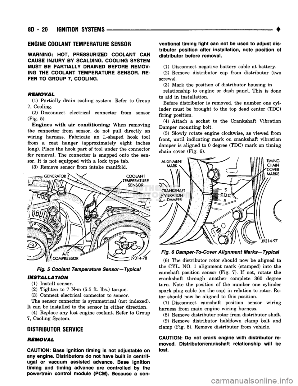
Disconnect electrical connector from sensor
(Fig. 5). Engines with air conditioning: When removing
the connector from sensor, do not pull directly on
wiring harness. Fabricate an L-shaped hook tool
from a coat hanger (approximately eight inches
long).
Place the hook part of tool under the connector
for removal. The connector is snapped onto the sen sor. It is not equipped with a lock type tab.
(3) Remove sensor from intake manifold.
Fig. 5 Coolant Temperature
Sensor—
Typical
INSTALLATION
(1) Install sensor.
(2) Tighten to 7 Nnn (5.5 ft. lbs.) torque.
(3) Connect electrical connector to sensor.
The sensor connector is symmetrical (not indexed).
It can be installed to the sensor in either direction. (4) Replace any lost engine coolant. Refer to Group
7, Cooling System.
DISTRIBUTOR
SERVICE
REMOVAL
CAUTION:
Base
ignition timing
is not
adjustable
on
any
engine. Distributors
do not
have
built
in
centrif
ugal
or
vacuum assisted advance.
Base
ignition
timing
and
timing advance
are
controlled
by the
powertrain control module
(PCM).
Because
a
con
ventional timing light can
not be
used
to
adjust
dis
tributor
position
after
installation, note position
of
distributor before removal.
(1) Disconnect negative battery cable at battery.
(2) Remove distributor cap from distributor (two
screws).
(3) Mark the position of distributor housing in
relationship to engine or dash panel. This is done
to aid in installation. Before distributor is removed, the number one cyl
inder must be brought to the top dead center (TDC)
firing position. (4) Attach a socket to the Crankshaft Vibration
Damper mounting bolt.
(5) Slowly rotate engine clockwise, as viewed from
front, until indicating mark on crankshaft vibration damper is aligned to 0 degree (TDC) mark on timing
chain cover (Fig. 6).
Fig. 6 Damper-To-Cover Alignment Marks—Typical (6) The distributor rotor should now be aligned to
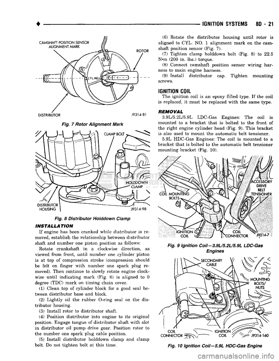
the CYL. NO. 1 alignment mark (stamped) into the camshaft position sensor (Fig. 7). If not, rotate the
crankshaft through another complete 360 degree
turn.
Note the position of the number one cylinder spark plug cable (on the cap) in relation to rotor. Ro
tor should now be aligned to this position.
(7) Disconnect camshaft position sensor wiring
harness from main engine wiring harness.
(8) Remove distributor rotor from distributor shaft. (9) Remove distributor holddown clamp bolt and
clamp (Fig. 8). Remove distributor from vehicle.
CAUTION: Do not
crank engine
with
distributor
re
moved.
Distributor/crankshaft relationship
will
be
lost.
Page 372 of 1502
IGNITION
SYSTEMS
80 - 21
DISTRIBUTOR
J9314-81
Fig.
7 Rotor Alignment Mark Fig. 8 Distributor Holddown Clamp
INSTALLATION
If engine has been cranked while distributor is re
moved, establish the relationship between distributor shaft and number one piston position as follows:
Rotate crankshaft in a clockwise direction, as
viewed from front, until number one cylinder piston is at top of compression stroke (compression should
be felt on finger with number one spark plug re moved). Then continue to slowly rotate engine clock
wise until indicating mark (Fig. 6) is aligned to 0
degree (TDC) mark on timing chain cover.
(1) Clean top of cylinder block for a good seal be
tween distributor base and block.
(2) Lightly oil the rubber O-ring seal on the dis
tributor housing.
(3) Install rotor to distributor shaft.
(4) Position distributor into engine to its original
position. Engage tongue of distributor shaft with slot in distributor oil pump drive gear. Position rotor to
the number one spark plug cable position.
(5) Install distributor holddown clamp and clamp
bolt. Do not tighten bolt at this time. (6) Rotate the distributor housing until rotor is
aligned to CYL. NO. 1 alignment mark on the cam
shaft position sensor (Fig. 7).
(7) Tighten clamp holddown bolt (Fig. 8) to 22.5
N*m (200 in. lbs.) torque. (8) Connect camshaft position sensor wiring har
ness to main engine harness. (9) Install distributor cap. Tighten mounting
screws.
IGNITION
COIL
The ignition coil is an epoxy filled type. If the coil
is replaced, it must be replaced with the same type.
REMOVAL
3.9L/5.2L/5.9L LDC-Gas Engines: The coil is
mounted to a bracket that is bolted to the front of
the right engine cylinder head (Fig. 9). This bracket is also used to mount the automatic belt tensioner.
5.9L HDC-Gas Engines: The coil is mounted to a
bracket that is bolted to the automatic belt tensioner mounting bracket (Fig. 10).
Fig.
9 Ignition Coil-3.9U5.2U5.9L
LDC-Gas
Engines
Fig.
10 Ignition Coil—5.9L
HDC-Gas
Engine
Page 375 of 1502
8D
- 24
IGNITION
SYSTEMS
•
.040
GAUGE
SPARK
"PLUG
J908D-10
Fig.
16 Setting
Spark Plug
Gap—Typical
SPARK
PLUG
SECONDARY
CABLES
CAUTION:
When disconnecting
a
high voltage cable
from
a
spark plug
or
from
the
distributor cap, twist
the rubber boot slightly
(1/2
turn)
to
break
it
loose.
Grasp
the
boot
(not
the
cable)
and
pull
it off
with
a
steady,
even force.
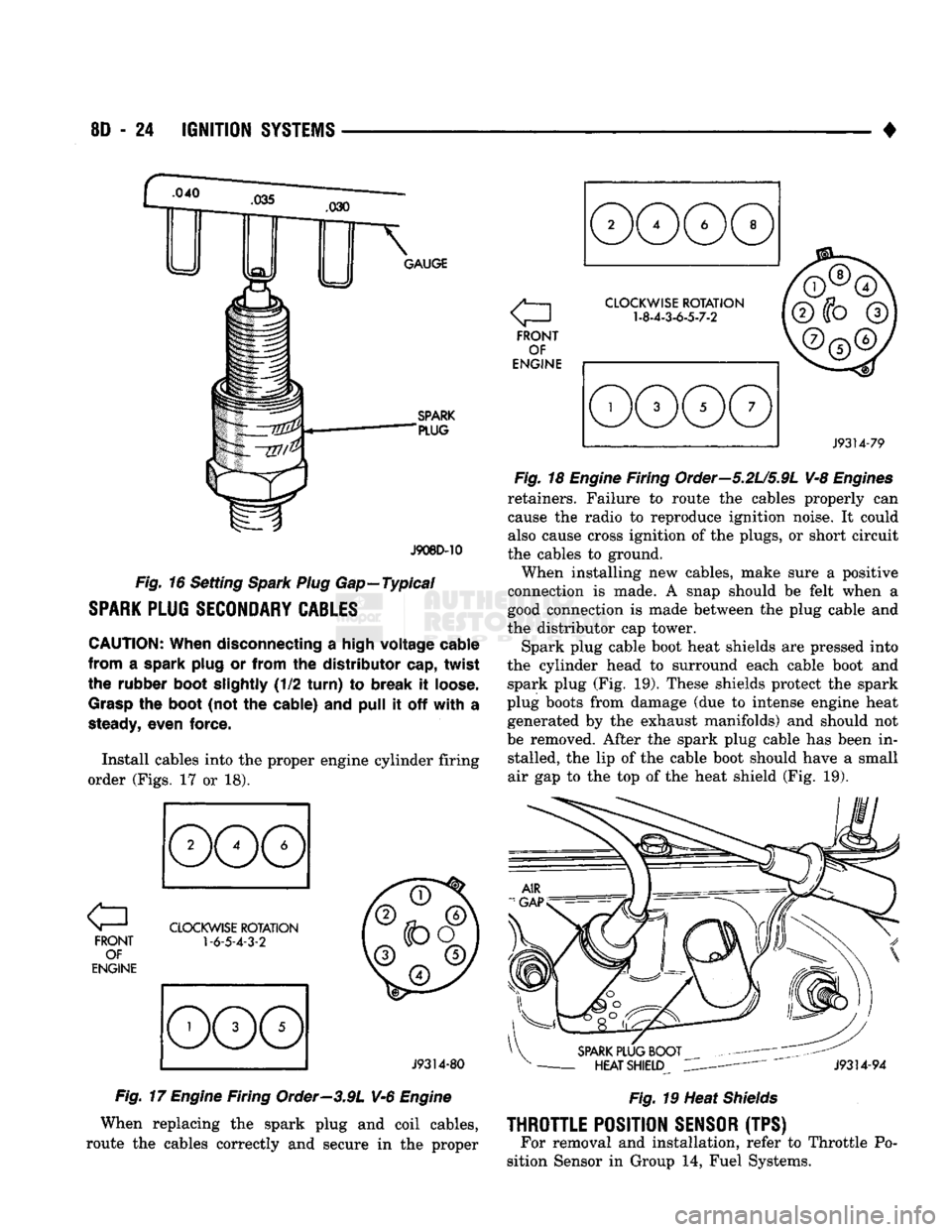
Install cables into
the
proper engine cylinder firing
order (Figs.
17 or 18).
FRONT OF
ENGINE
CLOCKWISE
ROTATION
1-6-5-4-3-2
J9314-80
Fig.
17
Engine
Firing Order—3.9L V-6
Engine
When replacing
the
spark plug
and
coil cables,
route
the
cables correctly
and
secure
in the
proper a
FRONT OF
ENGINE
CLOCKWISE
ROTATION
1-8-4-3-6-5-7-2
J9314-79
Fig.
18
Engine
Firing Order—5.2U5.9L V-8
Engines
retainers. Failure
to
route
the
cables properly
can
cause
the
radio
to
reproduce ignition noise.
It
could
also cause cross ignition
of the
plugs,
or
short circuit
the cables
to
ground.
When installing
new
cables, make sure
a
positive
connection
is
made.
A
snap should
be
felt when
a
good connection
is
made between
the
plug cable
and
the distributor
cap
tower.
Spark plug cable boot heat shields
are
pressed into
the cylinder head
to
surround each cable boot
and
spark plug
(Fig. 19).
These shields protect
the
spark
plug boots from damage
(due to
intense engine heat generated
by the
exhaust manifolds)
and
should
not
be removed. After
the
spark plug cable
has
been
in
stalled,
the lip of the
cable boot should have
a
small
air
gap to the top of the
heat shield
(Fig. 19).
SPARK
PLUG BOOT
-
HEAT SHIELD
J9314-94
Fig.
19 Heat
Shields
THROTTLE
POSITION
SENSOR
(TPS) For removal
and
installation, refer
to
Throttle
Po
sition Sensor
in
Group
14,
Fuel Systems.