1993 DODGE TRUCK power steering
[x] Cancel search: power steeringPage 28 of 1502
•
LUBRICATION AND MAINTENANCE
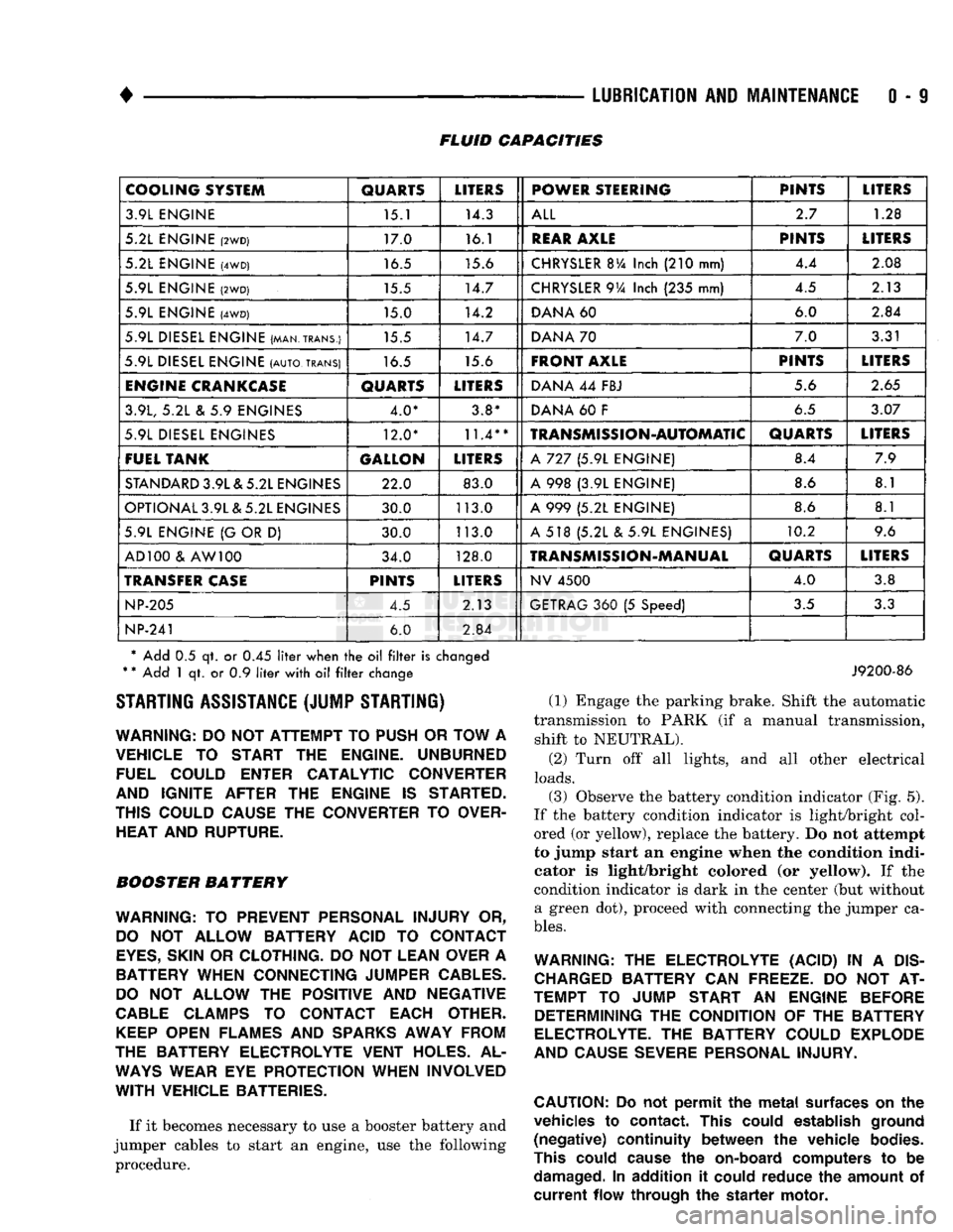
0 - 9 FLUID CAPACITIES
COOLING SYSTEM
QUARTS
LITERS
POWER STEERING PINTS
LITERS
3.9L ENGINE 15.1 14.3
ALL
2.7
1.28
5.2L ENGINE
(2WD)
17.0 16.1
REAR
AXLE
PINTS
LITERS
5.2L ENGINE
(4WD)
16.5 15.6
CHRYSLER
BVa
Inch
(210
mm) 4.4
2.08
5.9L ENGINE
(2WD)
15.5 14.7
CHRYSLER
9Va
Inch
(235
mm) 4.5
2.13
5.9L ENGINE
(4WD)
15.0 14.2
DANA
60 6.0
2.84
5.9L DIESEL ENGINE (MAN.TRANS.) 15.5 14.7
DANA
70 7.0
3.31
5.9L DIESEL ENGINE
(AUTO,
TRANS)
16.5 15.6
FRONT AXLE
PINTS
LITERS
ENGINE
CRANKCASE
QUARTS
LITERS
DANA
44
FBJ 5.6
2.65
3.9L,
5.2L & 5.9
ENGINES 4.0* 3.8*
DANA
60 F
6.5
3.07
5.9L DIESEL ENGINES 12.0*
11.4**
TRANSMISSION-AUTOMATIC
QUARTS
LITERS
FUEL TANK GALLON
LITERS
A
727 (5.9L
ENGINE) 8.4
7.9
STANDARD
3.9L & 5.2L ENGINES 22.0 83.0
A
998 (3.9L
ENGINE) 8.6
8.1
OPTIONAL 3.9L & 5.2L ENGINES 30.0 113.0
A
999 (5.2L
ENGINE) 8.6
8.1
5.9L ENGINE
{G
OR
D)
30.0 113.0
A
518 (5.2L & 5.9L
ENGINES) 10.2
9.6
AD 100
&
AW 100 34.0 128.0
TRANSMISSION-MANUAL
QUARTS
LITERS
TRANSFER
CASE
PINTS
LITERS
NV
4500
4.0
3.8
NP-205
4.5 2.13
GETRAG
360 (5
Speed)
3.5
3.3
NP-241
6.0
2.84
* Add
0.5 qt. or 0.45
liter
when
the oil filter
is
changed
*
*
Add
1 qt. or 0.9
liter
with
oil filter
change STARTING ASSISTANCE (JUMP STARTING)
WARNING:
DO NOT
ATTEMPT
TO
PUSH
OR
TOW
A
VEHICLE
TO
START
THE
ENGINE. UNBURNED FUEL COULD ENTER CATALYTIC CONVERTER
AND IGNITE AFTER
THE
ENGINE
IS
STARTED.
THIS COULD CAUSE
THE
CONVERTER
TO
OVER HEAT AND RUPTURE.
BOOSTER BATTERY
WARNING:
TO
PREVENT PERSONAL INJURY
OR,
DO
NOT
ALLOW BATTERY ACID
TO
CONTACT
EYES,
SKIN
OR
CLOTHING.
DO NOT
LEAN OVER
A
BATTERY WHEN CONNECTING JUMPER
CABLES.
DO
NOT
ALLOW
THE
POSITIVE
AND
NEGATIVE
CABLE
CLAMPS
TO
CONTACT EACH OTHER.
KEEP
OPEN FLAMES
AND
SPARKS
AWAY FROM
THE BATTERY ELECTROLYTE VENT HOLES.
AL
WAYS
WEAR
EYE
PROTECTION WHEN INVOLVED
WITH
VEHICLE BATTERIES.
If it becomes necessary to use a booster battery and
jumper cables to start an engine, use the following procedure.
J9200-86
(1) Engage the parking brake. Shift the automatic
transmission to PARK (if a manual transmission, shift to NEUTRAL).
(2) Turn off all lights, and all other electrical
loads.
(3)
Observe the battery condition indicator (Fig. 5).
If the battery condition indicator is light/bright col
ored (or yellow), replace the battery. Do not attempt
to jump start an engine when the condition indi
cator is light/bright colored (or yellow). If the
condition indicator is dark in the center (but without a green dot), proceed with connecting the jumper ca
bles.
WARNING:
THE
ELECTROLYTE (ACID)
IN A
DIS
CHARGED
BATTERY
CAN
FREEZE.
DO NOT AT
TEMPT
TO
JUMP START
AN
ENGINE BEFORE DETERMINING
THE
CONDITION
OF THE
BATTERY
ELECTROLYTE.
THE
BATTERY COULD EXPLODE
AND CAUSE SEVERE PERSONAL INJURY.
CAUTION:
Do not
permit
the
metal
surfaces
on the
vehicles
to
contact.
This
could
establish
ground
(negative)
continuity
between
the
vehicle
bodies.
This
could
cause
the
on-board
computers
to be
damaged.
In
addition
it
could
reduce
the
amount
of
current
flow
through
the
starter
motor.
Page 47 of 1502
0
- 28
LUBRICATION
AND
MAINTENANCE
•
CHASSIS AND BODY
page
Body
Component Mechanisms
32
Front
Suspension
Ball
Joints
28
Front
Wheel Bearings
29
Headlamps
32
Lower
and
Upper Suspension
Arm
Bushings
.... 30
Manual
Steering Gear
28
STEERING
LINKAGE
INSPECTION When
a
vehicle
is
raised
for
maintenance under
the vehicle,
all
steering components should
be
checked.
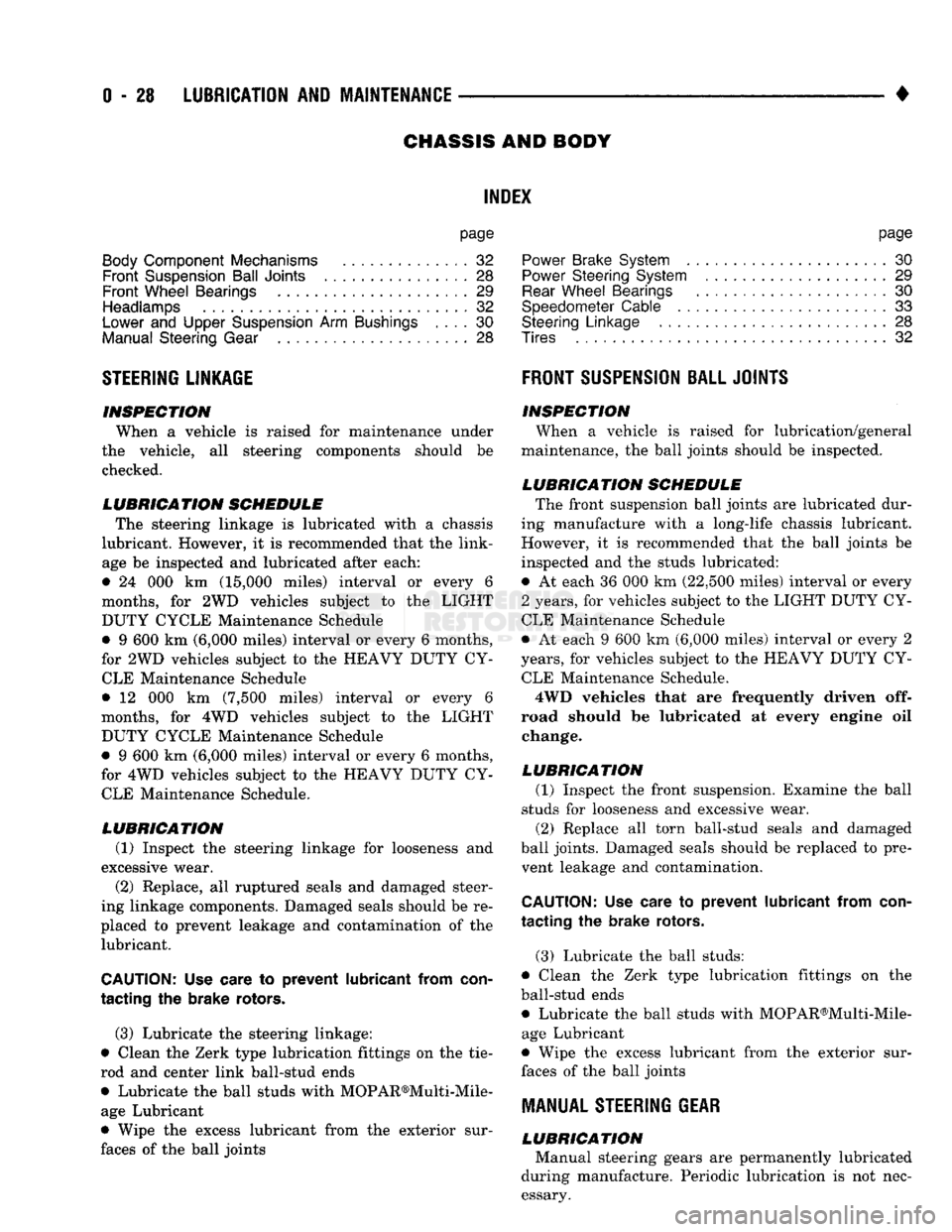
LUBRICATION SCHEDULE The steering linkage
is
lubricated with
a
chassis
lubricant. However,
it is
recommended that
the
link
age
be
inspected
and
lubricated after each:
•
24 000 km
(15,000 miles) interval
or
every
6
months,
for 2WD
vehicles subject
to the
LIGHT
DUTY CYCLE Maintenance Schedule
•
9 600 km
(6,000 miles) interval
or
every
6
months,
for
2WD
vehicles subject
to the
HEAVY DUTY
CY
CLE Maintenance Schedule
•
12 000 km
(7,500 miles) interval
or
every
6
months,
for 4WD
vehicles subject
to the
LIGHT DUTY CYCLE Maintenance Schedule
•
9 600 km
(6,000 miles) interval
or
every
6
months,
for
4WD
vehicles subject
to the
HEAVY DUTY
CY
CLE Maintenance Schedule.
LUBRICATION (1) Inspect
the
steering linkage
for
looseness
and
excessive wear. (2) Replace,
all
ruptured seals
and
damaged steer
ing linkage components. Damaged seals should
be re
placed
to
prevent leakage
and
contamination
of the
lubricant.
CAUTION:
Use
care
to
prevent lubricant from
con
tacting
the
brake rotors.
(3) Lubricate
the
steering linkage:
• Clean
the
Zerk type lubrication fittings
on the tie-
rod
and
center link ball-stud ends
• Lubricate
the
ball studs with MOPAR®Multi-Mile- age Lubricant
• Wipe
the
excess lubricant from
the
exterior sur
faces
of the
ball joints
page
Power
Brake System
30
Power
Steering System
. . 29
Rear
Wheel Bearings
30
Speedometer Cable
33
Steering Linkage
28
Tires
32
FRONT
SUSPENSION
BALL JOINTS
INSPECTION When
a
vehicle
is
raised
for
lubrication/general
maintenance,
the
ball joints should
be
inspected.
LUBRICATION SCHEDULE The front suspension ball joints
are
lubricated dur
ing manufacture with
a
long-life chassis lubricant.
However,
it is
recommended that
the
ball joints
be
inspected
and the
studs lubricated:
•
At
each
36 000 km
(22,500 miles) interval
or
every
2 years,
for
vehicles subject
to the
LIGHT DUTY
CY
CLE Maintenance Schedule
•
At
each
9 600 km
(6,000 miles) interval
or
every
2
years,
for
vehicles subject
to the
HEAVY DUTY
CY
CLE Maintenance Schedule.
4WD vehicles that
are
frequently driven
off-
road should
be
lubricated
at
every engine
oil
change.
LUBRICATION (1) Inspect
the
front suspension. Examine
the
ball
studs
for
looseness
and
excessive wear. (2) Replace
all
torn ball-stud seals
and
damaged
ball joints. Damaged seals should
be
replaced
to
pre vent leakage
and
contamination.
CAUTION:
Use
care
to
prevent lubricant from
con
tacting
the
brake rotors.
(3) Lubricate
the
ball studs:
• Clean
the
Zerk type lubrication fittings
on the
ball-stud ends
• Lubricate
the
ball studs with MOPAR®Multi-Mile-age Lubricant
• Wipe
the
excess lubricant from
the
exterior sur
faces
of the
ball joints
MANUAL
STEERING
GEAR
LUBRICATION Manual steering gears
are
permanently lubricated
during manufacture. Periodic lubrication
is not
nec
essary.
Page 48 of 1502
•
LUBRICATION
AND
MAINTENANCE
0 - 29
POWER STEERING SYSTEM
SERVICE SCHEDULE
FLUID
LEWEL
WARNING.
THE
POWER
STEERING
FLUID LEVEL
SHOULD
ALWAYS
BE
CHECKED
WITH THE EN
GINE
OFF TO
PREVENT
PERSONAL
INJURY.
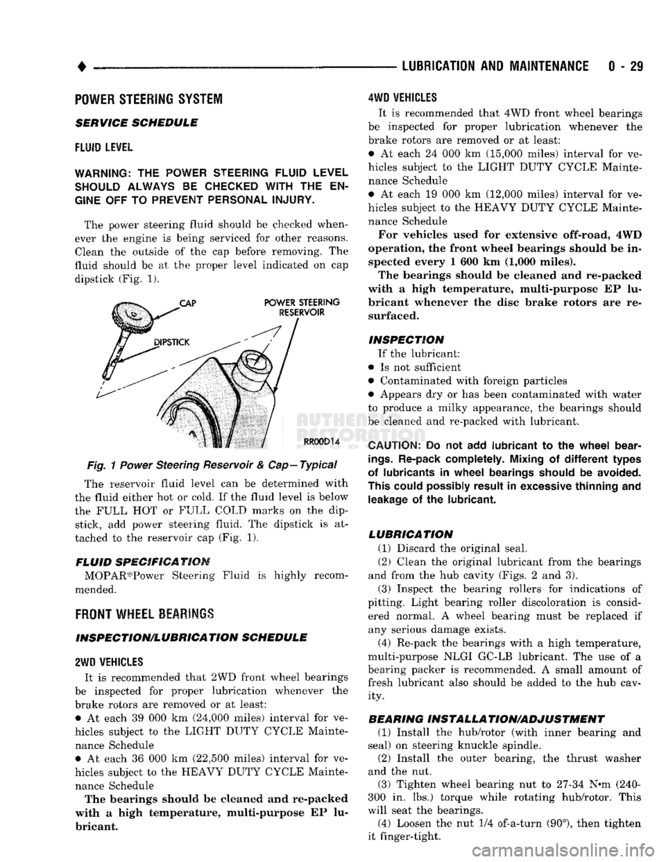
The power steering fluid should be checked when
ever the engine is being serviced for other reasons. Clean the outside of the cap before removing. The
fluid should be at the proper level indicated on cap dipstick (Fig. 1).
Fig.
1
Power
Steering Reservoir & Cap—Typical
The reservoir fluid level can be determined with
the fluid either hot or cold. If the fluid level is below
the FULL HOT or FULL COLD marks on the dip stick, add power steering fluid. The dipstick is at
tached to the reservoir cap (Fig. 1).
FLUID SPECIFICATION MOPAR03)Power Steering Fluid is highly recom
mended.
FRONT
WHEEL BEARINGS
INSPECTION/LUBRICATION SCHEDULE
2WD
VEHICLES
It is recommended that 2WD front wheel bearings
be inspected for proper lubrication whenever the
brake rotors are removed or at least: • At each 39 000 km (24,000 miles) interval for ve
hicles subject to the LIGHT DUTY CYCLE Mainte nance Schedule • At each 36 000 km (22,500 miles) interval for ve
hicles subject to the HEAVY DUTY CYCLE Mainte nance Schedule The bearings should be cleaned and re-packed
with a high temperature, multi-purpose EP lu
bricant.
4WD
VEHICLES
It is recommended that 4WD front wheel bearings
be inspected for proper lubrication whenever the
brake rotors are removed or at least:
• At each 24 000 km (15,000 miles) interval for ve
hicles subject to the LIGHT DUTY CYCLE Mainte nance Schedule
• At each 19 000 km (12,000 miles) interval for ve
hicles subject to the HEAVY DUTY CYCLE Mainte nance Schedule
For vehicles used for extensive off-road, 4WD
operation, the front wheel bearings should be in spected every 1 600 km (1,000 miles).
The bearings should be cleaned and re-packed
with a high temperature, multi-purpose EP lu
bricant whenever the disc brake rotors are re surfaced.
INSPECTION If the lubricant:
• Is not sufficient
• Contaminated with foreign particles
• Appears dry or has been contaminated with water
to produce a milky appearance, the bearings should
be cleaned and re-packed with lubricant.
CAUTION:
Do not add
lubricant
to the
wheel
bear
ings.
Re-pack completely. Mixing
of
different
types
of lubricants
in
wheel
bearings should
be
avoided.
This could possibly result
in
excessive thinning
and
leakage
of the
lubricant.
LUBRICATION (1) Discard the original seal.
(2) Clean the original lubricant from the bearings
and from the hub cavity (Figs. 2 and 3).
(3) Inspect the bearing rollers for indications of
pitting. Light bearing roller discoloration is consid ered normal. A wheel bearing must be replaced if any serious damage exists.
(4) Re-pack the bearings with a high temperature,
multi-purpose NLGI GC-LB lubricant. The use of a
bearing packer is recommended. A small amount of fresh lubricant also should be added to the hub cav ity.
BEARING INSTALLA TION/ADJUSTMENT (1) Install the hub/rotor (with inner bearing and
seal) on steering knuckle spindle.
(2) Install the outer bearing, the thrust washer
and the nut.
(3) Tighten wheel bearing nut to 27-34 N^m (240-
300 in. lbs.) torque while rotating hub/rotor. This
will seat the bearings.
(4) Loosen the nut 1/4 of-a-turn (90°), then tighten
it finger-tight.
Page 57 of 1502
2 - 4 FRONT SUSPENSION AND AXLE
•
I
FRONT END
|
|*?£E;
LOOSE
OR WORN
FRONT WHEEL
BEARINGS
LOOSE
C
SHOCKS
MOUNTir
WAR
SHOCK
A )RWORN
JSORBER
nIG
HARD-
E
OR
BSORBER
EXCiSSIVE
PLAY
STEERING
LINKAGE
LOOSE
OR WORN
FRONT WHEEL
BEARINGS
LOOSE
C
STEERINC
SHAFT
C
)RWORN
7
COLUMN
OUPLING
DIFFICULT
STEERING
LOOSE
OR WORN
WHEEL BEARINGS
TIRE/V
OUT OF
f
VHEEL
JA
LANCE
LOW OR UNEVEN
TIRE
AIR
PRESSURE
LO(
WHEEL B
DSE
EARINGS
LOW OR UNEVEN
TIRE AIR
PRESSURE
1vsnciEi
I
1
PULLS
TO I
I
|
ONE SIDE
j
LOOSE,
WORN
OR
GLAZED
P/S PUMP BELT LOW OR UNEVEN
TIRE PRESSURE
WHILE BR
REFE
BRAKES
AKING—
R
TO
SERVICE
LOOSE
STEERING
GEAR-TO-FRAME
RAIL BOLTS
LOOSE
STEERING
GEAR-TO-FRAME
RAIL BOLTS UNEVEN TIRE TREAD
WEAR,
OR
EX
CESSIVELY
WORN TIRE TREAD
BROKEN
OR WEAK
REAR
SPRING LOW
POWER STEERING
FLUID
LEVEL
BROKEN
OR WEAK
REAR
SPRING
WORN
UPPER
SUSPENSION ARM BUSHINGS WORN TIE-
ROD
END
BALL
STUDS WORN TIE-
ROD
END
BALL
STUDS
SHOCK
ABSORBER
NOT FUNCTIONING
CORRECTLY
LACK
OF ASSIST
FROM POWER
STEERING
PUMP
LOOSE
OR WORN
SUSPENSION
BUSHINGS
WORN LOWER
SUSPENSION
ARM
PIVOT
BUSHINGS INCORRECT
STEERING
GEAR ADJUSTMENT
LOOSE
OR WORN
SUSPENSION
ARM
BUSHINGS
INCORRECT
STEERING
GEAR ADJUSTMENT
BALL
STUDS
REQUIRE
LUBRICATION INCORRECT FRONT
WHEEL ALIGNMENT (EITHER CASTER OR CAMBER)
LOOSE
LOWER
SUSPENSION
ARM
LOOSE
OR WORN
UPPER
SUSPENSION ARM BALL STUDS
LOOSE
OR WORN
SUSPENSION
ARM
BUSHINGS
STEERING
GEAR
LUBRICANT LEVEL LOW
WORN ISOLATOR
PAD
BETWEEN COIL
SPRING
AND
FRAME
BRACKET INCORRECT FRONT-
WHEEL ALIGNMENT (PARTICULARLY
CASTER)
INCORRECT FRONT
WHEEL ALIGNMENT INCORRECT
STEERING
GEAR ADJUSTMENT
STEERING
GEAR
MALFUNCTION
INCORRECT FRONT
WHEEL ALIGNMENT (PARTICULARLY
CASTER)
J9002-97
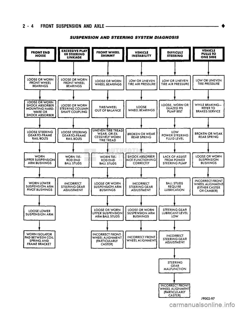
SUSPENSION AND STEERING
SYSTEM
DIAGNOSIS
Page 58 of 1502

•
FRONT
SUSPENSION
AND
AXLE
2 - 5 (4) Front wheels for excessive radial, lateral
runout and unbalance. Refer to Group 22, Wheels and Tires for diagnosis information.
(5) Suspension components for wear and noise. Check
components for correct torque. Refer to Groups 2 and 3, Suspension and Axle for additional information.
WHEEL
ALIGNMENT
MEASUREMENTS/ADJUSTMENTS
The front wheel alignment positions must be set to
the specified limits. This will prevent abnormal tire
tread wear. The equipment manufacturer's recommenda
tions for use of their
equipment
should always
be followed. All
damaged
front suspension sys
tem components
should
be replaced. Do not at tempt to straighten any
bent
component.
CAMBER AND CASTER-2WD VEHICLES Camber and caster angle adjustments involve repo
sitioning the upper suspension arm cam adjustment
bolts (Fig. 2). Alignment adjustments are accom
plished by loosening the nuts and changing the posi
tion of the cam bolt.
(1) Remove all foreign material from the adjust
ment bolt threads.
(2) Record the camber and caster measurements
before loosening the adjustment bolt nuts.
(3) The camber angle should be adjusted as near as
possible to the preferred angle. The caster should be
the same at both sides of the vehicle. Refer to the Specifications chart.
CAMBER AND CASTER—4WD VEHICLES For 4WD vehicles, the correct wheel camber (verti
cal tilt) angle is factory preset at zero degree (0°).
Camber cannot be altered by adjustment.
CAUTION: Do not attempt to
adjust
the
camber
an
gle by
heating
or bending the axle or any
suspen
sion
component. If camber angle is
incorrect,
the
component(s)
causing
an
incorrect
angle must be replaced.
(1) It is important that the camber (vertical tilt)
angle be the same for both front wheels.
(2) The camber angle should be measured with ac
curate wheel alignment equipment. The acceptable
range is -1° to +1°. Refer to the Specifications chart.
Road test the vehicle and observe the steering
wheel return-to-center position. Before road testing,
check
and
correct
the tire
inflation pressures. Inflate
both
of the front tires
with exactly the
same
pressure.
During the road test, make vehicle turns to both
the left and right. If the steering wheel returns to
ward the center position unassisted, the caster angle is correct. However, if the steering wheel does not re turn toward the center position unassisted, an incor
rect caster angle is probable.
(1) The caster angle is factory preset at positive
two degrees
(
+
2°).
The acceptable range is +1/2° to +
3
1/2°.
(2) The caster angle should be measured with ac
curate wheel alignment equipment.
(3) Caster angle can be adjusted by installing ta
pered shims between the front axle pads and the spring brackets. The caster angle should be adjusted
as near as possible to the preferred angle.
(4) Record the caster measurement before remov
ing the original shims from the spring pads.
(5) The caster should be the same at both sides of
the vehicle. Refer to the Specifications chart.
RN1030
Fig.
2 Caster &
Camber
Adjustment Location—2WD
Vehicles
WHEEL TOE POSITION The wheel toe position adjustment should be the fi
nal front wheel alignment adjustment. In all in stances, follow the equipment manufacturer's
recommended procedure.
(1) Secure the steering wheel with the front wheels
in the straight-ahead position. For vehicles equipped
with power steering, start the engine before straight ening the wheels.
With power steering, the engine should be op
erating during the wheel toe position adjust
ment.
(2) Loosen the tie rod adjustment sleeve clamp
bolts (Fig. 3).
(3) Adjust the wheel toe position by rotating the
tie rod adjustment sleeve (Fig. 3). Rotate each tie-rod end in the direction of
sleeve rotation during the adjustment (Fig. 3).
This will ensure that both tie-rod ends are at the center of their travel.
(4) If applicable, turn the ignition switch off.
Page 190 of 1502

•
BRAKES
i - 3 BRAKE DIAGNOSIS
INDEX
page
Brake
Warning Lights
3
Diagnosing
Brake Problems .................
4
Diagnosis
Procedures
3
Low
Vacuum
Switch—Diesel
Models
3
page
Master
Cylinder/Power Booster Test
5
Power
Booster
Check
Valve Test .............
6
Power
Booster
Vacuum
Test .................
6
Testing Diesel
Engine
Vacuum
Pump
Output
.... 6
DIAGNOSIS
PROCEDURES
Brake diagnosis involves determining
if the
prob
lem
is
related
to a
mechanical, hydraulic
or
vacuum
operated component.
A
preliminary check, road test
ing
and
component inspection
can all be
used
to de
termine
a
problem cause. Road testing will either verify proper brake opera
tion
or
confirm
the
existence
of a
problem. Compo nent inspection will,
in
most cases, identify
the
actual part causing
a
problem. The first diagnosis step
is the
preliminary check. This
involves inspecting fluid level, parking brake action,
wheel
and
tire condition, checking
for
obvious leaks
or
component damage
and
testing brake pedal response. A road test will confirm
the
existence
of a
problem.
Final diagnosis procedure involves road test analysis and
a
visual inspection
of
brake components.
BRAKE
WARNING LIGHTS
The
red
brake warning light
is
connected
to the
parking brake switch
and to the
pressure differential switch
in the
combination valve. The
red
light will illuminate when
the
parking
brakes
are
applied
or
when
a
fluid pressure drop
oc
curs
in the
front
or
rear brake circuit.
The
light will
also illuminate
for
approximately
2-4
seconds
at en
gine start
up.
This
is a
self test feature designed
to
check bulb
and
circuit operation each time
the en
gine
is
started. The amber antilock light
is
connected
to the
anti-
lock rear brake hydraulic valve.
The
light will illu
minate
if a
fault occurs within
the
antilock system.
LOW VACUUM SWITCH-DIESEL MODELS
On diesel models,
the red
brake warning light
is
also
used
to
alert
the
driver
of a low
brake booster vacuum
condition.
The
warning light
is in
circuit with
a
vacuum
warning switch mounted
on the
driver side fender
panel.
The
vacuum side
of the
switch
is
connected
to the
power brake booster.
The
electrical side
of the
switch
is
connected
to the
brake warning light. The
low
vacuum switch monitors booster vacuum
level whenever
the
engine
is
running.
If
booster vac
uum falls below
8.5
inches vacuum
for a
minimum
of
10 seconds,
the
switch completes
the
circuit
to the
warning light causing
it to
illuminate.
The
warning light
is
designed
to
differentiate between
a low
vac
uum condition
and a
hydraulic circuit fault.
PRELIMINARY
BRAKE CHECK
(1) Check condition
of
tires
and
wheels. Damaged
wheels
and
worn, damaged,
or
underinflated tires
can
cause pull, shudder, tramp,
and a
condition similar
to
grab.
(2)
If
complaint
was
based
on
noise when braking,
check suspension components. Jounce front
and
rear
of
vehicle
and
listen
for
noise that might
be
caused
by
loose, worn
or
damaged suspension
or
steering compo
nents.
(3) Inspect brake fluid level
and
condition. Note
that
the
front disc brake reservoir fluid level will drop
in
proportion
to
normal lining wear. Also note
that brake fluid tends
to
darken over time. This
is normal
and
should
not be
mistaken
for
con
tamination.
If the
fluid
is
still clear
and
free
of
foreign material,
it is OK.
(a)
If
fluid level
is
abnormally
low,
look
for
evi
dence
of
leaks
at
calipers, wheel cylinders, brake-
lines
and
master cylinder.
(b)
If
fluid appears contaminated, drain
out a
sample.
If
fluid
is
separated into layers,
or
obvi
ously contains
oil or a
substance other than brake
fluid,
the
system seals
and
cups will have
to be re
placed
and the
hydraulic system flushed.
(4) Check parking brake operation. Verify free
movement
and
full release
of
cables
and
pedal. Also
note
if
vehicle
was
being operated with parking
brake partially applied.
(5) Check brake pedal operation. Verify that pedal
does
not
bind
and has
adequate free play.
If
pedal
lacks free play, check pedal
and
power booster
for be
ing loose
or for
bind condition.
Do not
road test until
condition
is
corrected.
(6)
If
components checked appear
OK,
road test
the
vehicle.
ROAD
TESTING (1)
If
complaint involved
low
brake pedal, pump
the pedal
and
note
if the
pedal comes back
up to
nor mal height.
(2) Check brake pedal response with transmission
in Neutral
and
engine running. Pedal should remain
firm under steady foot pressure.
Page 192 of 1502

•
BRAKES
5 - 5 Disc brake rotors with excessive lateral runout or
thickness variation, or out of round brake drums are
the primary causes of pulsation. Other causes are loose
wheel bearings or calipers and worn, damaged tires.
PULL A
front pull condition could be the result of con
taminated lining in one caliper, seized caliper piston,
binding caliper, loose caliper, loose or corroded slide
pins,
improper brakeshoes, or a damaged rotor.
A worn, damaged wheel bearing or suspension compo
nent are further causes of pull. A damaged front tire (bruised, ply separation) can also cause pull.
A common and frequently misdiagnosed pull condi
tion is where direction of pull changes after a few
stops.
The cause is a combination of brake drag fol
lowed by fade at one of the brake units.
As the dragging brake overheats, efficiency is so
reduced that fade occurs. Since the opposite brake
unit is still functioning normally, its braking effect is
magnified. This causes pull to switch direction in fa
vor of the normally functioning brake unit.
When diagnosing a change in pull condition, re
member that pull will return to the original direction
if the dragging brake unit is allowed to cool down (and is not seriously damaged).
REAR BRAKE GRAB
OR
PULL
Rear grab or pull is usually caused by an improperly
adjusted or seized parking brake cable, contaminated
lining, bent or binding shoes and support plates, or im
properly assembled components. This is particularly
true when only one rear wheel is involved. However,
when both rear wheels are affected, the master cylinder or proportioning valve could be at fault.
BRAKES
DO NOT
HOLD
AFTER
DRIVING
THROUGH
DEEP
WATER
PUDDLES
This condition is generally caused by water soaked
lining. If the lining is only wet, it can be dried by driv
ing with the brakes very lightly applied for a few min
utes.
However, if the lining is thoroughly wet and dirty,
disassembly and cleaning will be necessary.
BRAKE NOISE
Squeak/Squeal
Brake squeak or squeal may be due to linings that
are wet or contaminated with brake fluid, grease, or oil. Glazed linings and rotors with hard spots can also con
tribute to squeak. Dirt and foreign material embedded in the brake lining can also cause squeak/squeal.
A very loud squeak or squeal is frequently a sign of
severely worn brake lining. If the lining has worn
through to the brakeshoes in spots, metal-to-metal con
tact occurs. If the condition is allowed to continue, ro tors can become so scored that replacement is necessary.
Thump/Clunk
Thumping or clunk noises during braking are fre
quently not caused by brake components. In many
cases,
such noises are caused by loose or damaged steering, suspension, or engine components. How
ever, calipers that bind on the slide pins, or slide sur
faces,
can generate a thump or clunk noise. Worn
out, improperly adjusted, or improperly assembled
rear brakeshoes can also produce a thump noise.
Chatter
Brake chatter is usually caused by loose or worn
components, or glazed/burnt lining. Rotors with hard
spots can also contribute to chatter. Additional
causes of chatter are out of tolerance rotors, brake
lining not securely attached to the shoes, loose wheel
bearings and contaminated brake lining.
Brakelining Contamination Brakelining contamination is usually a product of
leaking calipers or wheel cylinders, driving through
deep water puddles, or lining that has become cov
ered with grease and grit during repair.
Wheel and
Tire
Problems Some conditions attributed to brake components
may actually be caused by a wheel or tire problem.
A damaged wheel can cause shudder, vibration and
pull. A worn or damaged tire can also cause pull.
Severely worn tires with very little tread left can
produce a grab-like condition as the tire loses and re covers traction. Flat-spotted tires can cause vibration and wheel
tramp and generate shudder during brake operation. A tire with internal damage such as a severe
bruise or ply separation can cause pull and vibration.
MASTER
CYLINDER/POWER BOOSTER TEST
(1) Start engine and check booster vacuum hose
connections. Hissing noise indicates a vacuum leak. Correct any leaks before proceeding. (2) Stop engine and shift transmission into Neu
tral (3) Pump brake pedal until all vacuum reserve in
booster is depleted. (4) Press and hold brake pedal under light foot
pressure. (a) If pedal holds firm, proceed to step (5).
(b) If pedal does not hold firm and falls away,
master cylinder is faulty (internal leakage). (5) Start engine and note pedal action. (a) If pedal falls away slightly under light foot
pressure then holds firm, proceed to step (6). (b) If pedal is effort is high, or no pedal action is
discernible, power booster or vacuum check valve is
faulty. Install known good check valve and repeat steps (2) through (5).
Page 207 of 1502
5
- 20
BRAKES
•
POWER BRAKE BOOSTER—BRAKE PEDAL
INDEX
page
Brake Pedal
Installation
21
Brake Pedal Removal
21
General
Information
.......................
20
page
Power Brake Booster
Installation
.............
21
Power Brake Booster Removal
21
GENERAL
INFORMATION
Power brakes
are
standard
on all AD
models.
A
single
or
dual diaphragm, vacuum power brake
booster
is
used. AD
and W150
models
are
equipped with
a
single
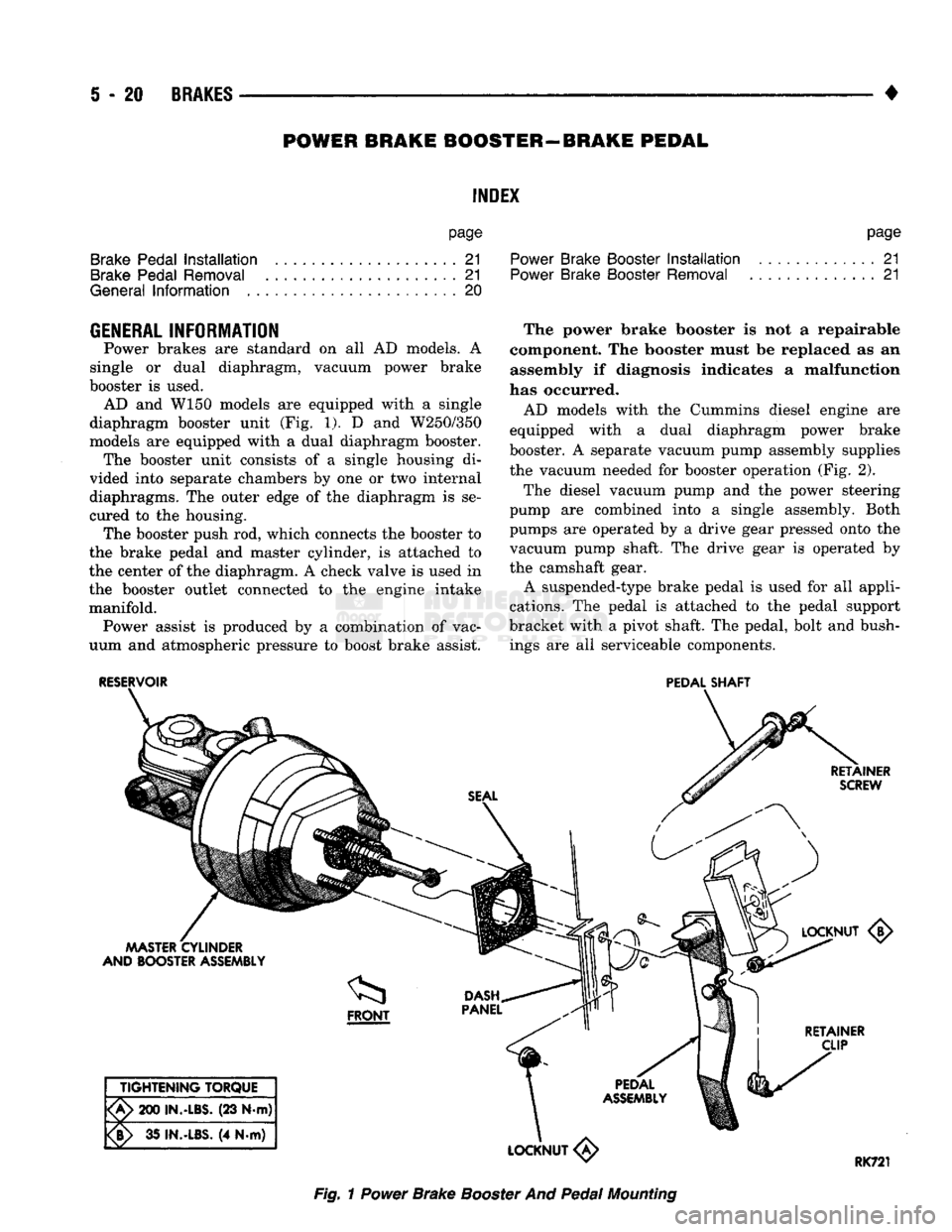
diaphragm booster unit
(Fig. 1). D and
W250/350
models
are
equipped with
a
dual diaphragm booster. The booster unit consists
of a
single housing
di
vided into separate chambers
by one or two
internal
diaphragms.
The
outer edge
of the
diaphragm
is se
cured
to the
housing. The booster push
rod,
which connects
the
booster
to
the brake pedal
and
master cylinder,
is
attached
to
the center
of the
diaphragm.
A
check valve
is
used
in
the booster outlet connected
to the
engine intake manifold. Power assist
is
produced
by a
combination
of
vac
uum
and
atmospheric pressure
to
boost brake assist. The power brake booster
is not a
repairable
component.
The
booster must
be
replaced
as an
assembly
if
diagnosis indicates
a
malfunction
has occurred.
AD models with
the
Cummins diesel engine
are
equipped with
a
dual diaphragm power brake
booster.
A
separate vacuum pump assembly supplies the vacuum needed
for
booster operation
(Fig. 2).
The diesel vacuum pump
and the
power steering
pump
are
combined into
a
single assembly. Both
pumps
are
operated
by a
drive gear pressed onto
the
vacuum pump shaft.
The
drive gear
is
operated
by
the camshaft gear. A suspended-type brake pedal
is
used
for all
appli
cations.
The
pedal
is
attached
to the
pedal support
bracket with
a
pivot shaft.
The
pedal, bolt
and
bush ings
are all
serviceable components.
RESERVOIR
PEDAL
SHAFT
RETAINER
SCREW
MASTER
CYLINDER
AND BOOSTER
ASSEMBLY <5>
I
RETAINER
CLIP
TIGHTENING
TORQUE
'A>
200
IN.-LBS.
(23 N-m)
¥>
35
IN.-LBS.
(4 N.m)
LOCKNUT
«
RK721
Fig.
1
Power
Brake
Booster
And
Pedal
Mounting