1993 DODGE TRUCK power steering
[x] Cancel search: power steeringPage 208 of 1502
•
BRAKES
5 - 21
VACUUM
GEAR
ADAPTER
J9105-94
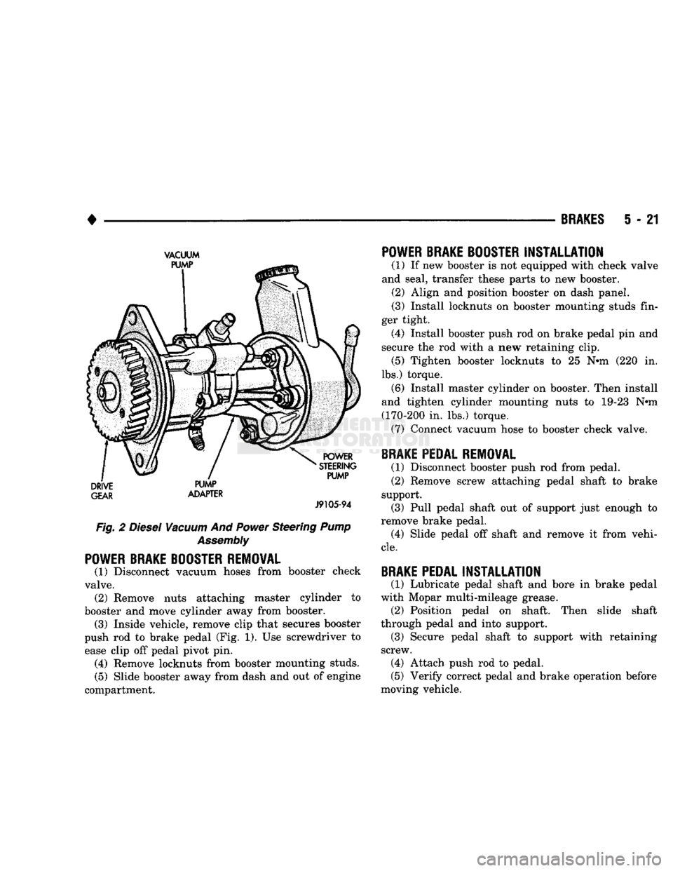
Fig. 2
Diesel
Vacuum
And
Power
Steering
Pump
Assembly
POWER BRAKE BOOSTER REMOVAL
(1) Disconnect vacuum hoses from booster check
valve. (2) Remove nuts attaching master cylinder to
booster and move cylinder away from booster. (3) Inside vehicle, remove clip that secures booster
push rod to brake pedal (Fig. 1). Use screwdriver to ease clip off pedal pivot pin. (4) Remove locknuts from booster mounting studs.
(5) Slide booster away from dash and out of engine
compartment.
POWER BRAKE BOOSTER
INSTALLATION
(1) If new booster is not equipped with check valve
and seal, transfer these parts to new booster. (2) Align and position booster on dash panel.
(3) Install locknuts on booster mounting studs fin
ger tight. (4) Install booster push rod on brake pedal pin and
secure the rod with a new retaining clip. (5) Tighten booster locknuts to 25 Nth (220 in.
lbs.) torque. (6) Install master cylinder on booster. Then install
and tighten cylinder mounting nuts to 19-23 Nnn
(170-200 in. lbs.) torque. (7) Connect vacuum hose to booster check valve.
BRAKE PEDAL REMOVAL
(1) Disconnect booster push rod from pedal. (2) Remove screw attaching pedal shaft to brake
support. (3) Pull pedal shaft out of support just enough to
remove brake pedal. (4) Slide pedal off shaft and remove it from vehi
cle.
BRAKE PEDAL
INSTALLATION
(1) Lubricate pedal shaft and bore in brake pedal
with Mopar multi-mileage grease. (2) Position pedal on shaft. Then slide shaft
through pedal and into support. (3) Secure pedal shaft to support with retaining
screw. (4) Attach push rod to pedal.
(5) Verify correct pedal and brake operation before
moving vehicle.
Page 209 of 1502
5
- 22
BRAKES
POWER BRAKE
VACUUM
PUMP—DIESEL ENGINE
INDEX
page
General
Information
22
Low
Vacuum
Warning
Switch
22
Pump
Adapter
Replacement
. 25
Vacuum
Pump
Diagnosis
..................
23
Vacuum
Pump
Operation
..................
23
page
Vacuum
Pump
Replacement
24
Vacuum
Pump
Serviceability
22
Vacuum—Steering
Pump
Assembly
Installation
. . 26
Vacuum—Steering
Pump
Assembly
Removal
... 23
GENERAL
INFORMATION
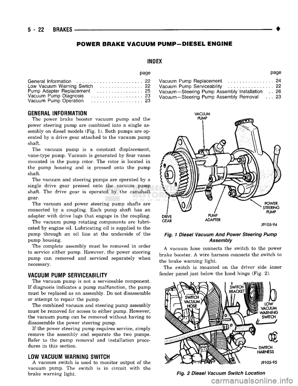
The power brake booster vacuum pump
and the
power steering pump
are
combined into
a
single
as
sembly
on
diesel models
(Fig. 1).
Both pumps
are op
erated
by a
drive gear attached
to the
vacuum pump shaft. The vacuum pump
is a
constant displacement,
vane-type pump. Vacuum
is
generated
by
four vanes
mounted
in the
pump rotor.
The
rotor
is
located
in
the pump housing
and is
pressed onto
the
pump shaft. The vacuum
and
steering pumps
are
operated
by a
single drive gear pressed onto
the
vacuum pump
shaft.
The
drive gear
is
operated
by the
camshaft
gear. The vacuum
and
power steering pump shafts
are
connected
by a
coupling. Each pump shaft
has an
adapter with drive lugs that engage
in the
coupling. The vacuum pump rotating components
are
lubri
cated
by
engine
oil.
Lubricating
oil is
supplied
to the
pump through
an oil
line
at the
underside
of the
pump housing. The complete assembly must
be
removed
in
order
to service either pump. However,
the
power steering
pump
can
removed
and
serviced separately when necessary.
VACUUM
PUMP
SERVICEABILITY
The vacuum pump
is not a
serviceable component.
If diagnosis indicates
a
pump malfunction,
the
pump must
be
replaced
as an
assembly.
Do not
disassemble
or attempt
to
repair
the
pump.
The combined vacuum
and
steering pump assembly
must
be
removed
for
access
to
either pump. However,
the vacuum pump
can be
removed without having
to
disassemble
the
power steering pump. If
the
power steering pump requires service, simply
remove
the
assembly
and
separate
the two
pumps. Refer
to the
pump removal
and
installation procedures
in
this section.
LOW
VACUUM
WARNING
SWITCH
A vacuum switch
is
used
to
monitor output
of the
vacuum pump.
The
switch
is in
circuit with
the
brake warning light.
VACUUM
PUMP
DRIVE
GEAR
PUMP
ADAPTER
POWER
STEERING
PUMP
J9105-94
Fig.
1
Diesel
Vacuum
And
Power
Steering
Pump
Assembly
A vacuum hose connects
the
switch
to the
power
brake booster.
A
wire harness connects
the
switch
to
the brake warning light.
The switch
is
mounted
on the
driver side inner
fender panel just below
the
hood hinge
(Fig. 2),
b
LOW
VACUUM
WARNING
SWITCH
SWITCH
HARNESS
J9105-95
Fig.
2
Diesel
Vacuum
Switch
Location
Page 210 of 1502
•
BRAKES
5 - 23
VACUUM PUMP OPERATION
Vacuum pump output is transmitted to the power
brake booster through a supply hose. The hose is con nected to an outlet port on the pump housing and to
the check valve in the power brake booster.
Pump output ranges from a minimum of 8.5 to 25
inches vacuum. The pump rotor and vanes are rotated by the pump
drive gear. The drive gear is operated by the cam
shaft gear. Booster vacuum level is monitored by a warning
switch (Fig. 2). The switch consists of a vacuum
chamber that measures vacuum level and a sensor in
circuit with the brake warning light. The vacuum chamber is connected to the booster
check valve by a vacuum supply hose. A wire har
ness connects the switch sensor to the brake warning
light. If booster vacuum falls below 8.5 inches for 8-10 seconds or more, the switch sensor completes
the circuit to the warning light causing it to illumi
nate.
VACUUM PUMP DIAGNOSIS
Vacuum pump diagnosis involves checking pump
output with a vacuum gauge. The low vacuum warn
ing switch can also be checked with a vacuum gauge.
Refer to the diagnosis procedure in this section. A standard vacuum gauge can be used to check
pump output when necessary. Simply disconnect the
pump supply hose and connect a vacuum gauge to
the outlet port for testing purposes. Vacuum should
hold steady in a range of approximately 8.5 to 25 inches at various engine speeds.
DIAGNOSING LOW VACUUM OUTPUT CONDITION A low booster vacuum condition or a faulty low
vacuum warning switch will cause the brake warn ing light to illuminate. If the light does go on and in
dicates the existence of a low vacuum condition,
check the vacuum pump, booster and warning switch
as follows:
(1) Check vacuum pump oil feed line. Verify that
line connections are secure and not leaking. If leak age is noted and pump is noisy, replace pump.
(2) Disconnect supply hose to booster. Connect vac
uum gauge to this hose and run engine at various
throttle openings. Output should range from 8.5 to 25 inches vacuum. If vacuum is consistently below
8.5 inches, problem is with vacuum hoses or pump
component. If output is within specified limits, con
tinue testing.
(3) Check booster operation as described in diagno
sis section. Replace check valve, vacuum hoses, or
booster if necessary. However, if booster operation is correct but warning light is still on, continue testing. (4) Disconnect vacuum hose at warning switch.
Plug hose and connect hand vacuum pump to switch. (5) Start and run engine.
(6) Apply 8.5 to 9 inches of vacuum to warning
switch and observe warning light. If light goes out,
switch vacuum hose is either loose or leaking. If
light remains on, leave engine running and continue
testing.
(7) Apply 20-25 inches vacuum to switch and ob
serve warning light operation. If light now goes out,
switch is at fault and should be replaced. If light re
mains on, continue testing.
(8) Reconnect vacuum hoses and replace original
warning switch with known good switch. Run engine and observe warning light operation. If light is now
off, old switch is faulty. If light remains on, problem
is in wiring between switch and warning light.
VACUUM-STEERING PUMP
ASSEMBLY
REMOVAL
(1) Disconnect battery negative cable.
(2) Position drain pan under power steering pump.
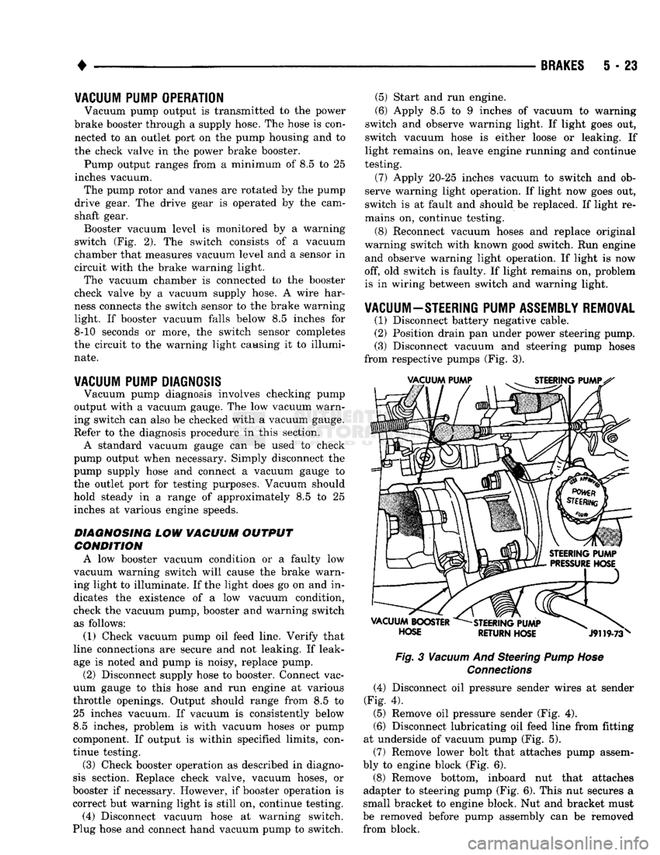
(3) Disconnect vacuum and steering pump hoses
from respective pumps (Fig. 3).
Fig.
3
Vacuum
And Steering
Pump Hose
Connections
(4) Disconnect oil pressure sender wires at sender
(Fig. 4).
(5) Remove oil pressure sender (Fig. 4).
(6) Disconnect lubricating oil feed line from fitting
at underside of vacuum pump (Fig. 5).
(7) Remove lower bolt that attaches pump assem
bly to engine block (Fig. 6).
(8) Remove bottom, inboard nut that attaches
adapter to steering pump (Fig. 6). This nut secures a
small bracket to engine block. Nut and bracket must
be removed before pump assembly can be removed from block.
Page 213 of 1502
5
- 26
BRAKES
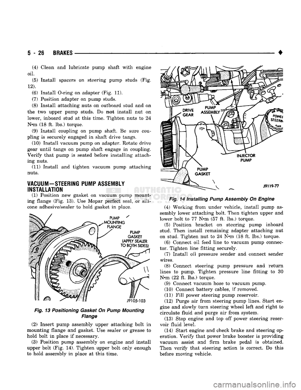
Fig. 13 Positioning Gasket On Pump Mounting
Flange
(2) Insert pump assembly upper attaching bolt in
mounting flange and gasket. Use sealer or grease to
hold bolt in place if necessary.
(3) Position pump assembly on engine and install
upper bolt (Fig. 14). Tighten upper bolt only enough
to hold assembly in place at this time. •
Fig. 14 Installing Pump Assembly On Engine (4) Working from under vehicle, install pump as
sembly lower attaching bolt. Then tighten upper and
lower bolt to 77 N»m (57 ft. lbs.) torque. (5) Position bracket on steering pump inboard
stud. Then install remaining adapter attaching nut
on stud. Tighten nut to 24 N«m (18 ft. lbs.) torque.
(6) Connect oil feed line to vacuum pump connec
tor. Tighten line fitting securely.
(7) Install oil pressure sender and connect sender
wires.
(8) Connect steering pump pressure and return
lines to pump. Tighten pressure line fitting to 30
N-m (22 ft. lbs.) torque.
(9) Connect vacuum hose to vacuum pump.
(10) Connect battery cables, if removed.
(11) Fill power steering pump reservoir.
(12) Purge air from steering pump lines. Start en
gine and slowly turn steering wheel left and right to circulate fluid and purge air from system.
(13) Stop engine and top off power steering reser
voir fluid level.
(14) Start engine and check brake and steering op
eration. Verify that power brake booster is providing
vacuum assist and firm brake pedal is obtained.
Then verify that steering action is correct. Do this
before moving vehicle.
(4) Clean and lubricate pump shaft with engine
oil.
(5) Install spacers on steering pump studs (Fig.
12).
(6) Install O-ring on adapter (Fig. 11).
(7) Position adapter on pump studs.
(8) Install attaching nuts on outboard stud and on
the two upper pump studs. Do not install nut on
lower, inboard stud at this time. Tighten nuts to 24
N-m (18 ft. lbs.) torque. (9) Install coupling on pump shaft. Be sure cou
pling is securely engaged in shaft drive tangs. (10) Install vacuum pump on adapter. Rotate drive
gear until tangs on pump shaft engage in coupling.
Verify that pump is seated before installing attach
ing nuts. (11) Install and tighten vacuum pump attaching
nuts.
VACUUM-STEERING PUMP ASSEMBLY INSTALLATION
(1) Position new gasket on vacuum pump mount
ing flange (Fig. 13). Use Mopar perfect seal, or sili
cone adhesive/sealer to hold gasket in place.
Page 289 of 1502
7 - 18
COOLING
SYSTEM
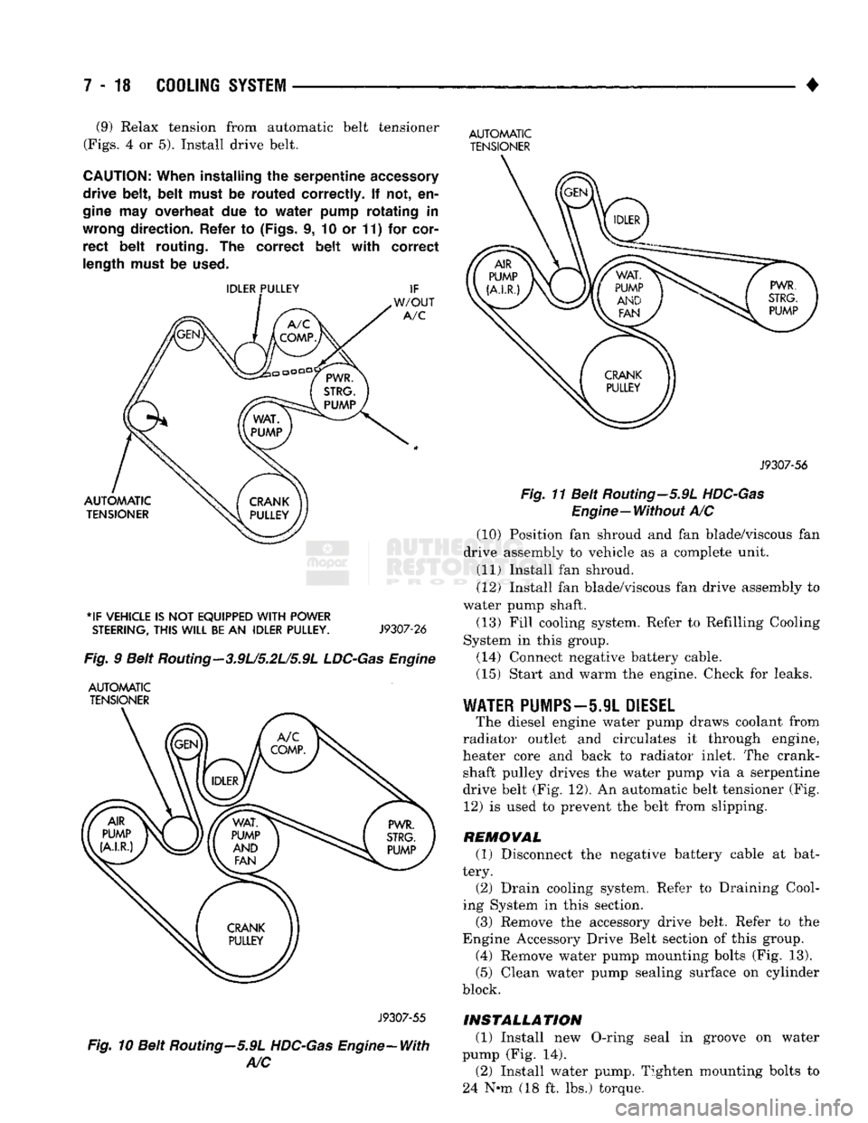
• (9) Relax tension from automatic belt tensioner
(Figs.
4 or 5). Install drive belt.
CAUTION:
When
installing
the
serpentine
accessory
drive
belt, belt
must
be
routed
correctly.
If not, en
gine
may
overheat
due to
water
pump
rotating
in
wrong
direction.
Refer
to
(Figs,
i, 10 or 11) for
cor
rect
belt
routing.
The
correct
belt with
correct
length
must
be
used.
*IF
VEHICLE
IS NOT
EQUIPPED
WITH
POWER
STEERING,
THIS
WILL
BE
AN
IDLER
PULLEY.
J9307-26
Fig.
9 Belt Routing—3.9U5.2L/5.9L
LDC-Gas
Engine
AUTOMATIC
TENSIONER
AUTOMATIC
TENSIONER
J9307-56
Fig.
11 Belt Routing—5.9L
HDC-Gas
Engine—Without
A/C (10) Position fan shroud and fan blade/viscous fan
drive assembly to vehicle as a complete unit. (11) Install fan shroud.
(12) Install fan blade/viscous fan drive assembly to
water pump shaft.
(13) Fill cooling system. Refer to Refilling Cooling
System in this group. (14) Connect negative battery cable.
(15) Start and warm the engine. Check for leaks.
WATER
PUMPS—5.9L
DIESEL
The diesel engine water pump draws coolant from
radiator outlet and circulates it through engine,
heater core and back to radiator inlet. The crank shaft pulley drives the water pump via a serpentine
drive belt (Fig. 12). An automatic belt tensioner (Fig. 12) is used to prevent the belt from slipping.
REMOVAL (1) Disconnect the negative battery cable at bat
tery. (2) Drain cooling system. Refer to Draining Cool
ing System in this section.
(3) Remove the accessory drive belt. Refer to the
Engine Accessory Drive Belt section of this group. (4) Remove water pump mounting bolts (Fig. 13).
(5) Clean water pump sealing surface on cylinder
block.
J9307-55
Fig.
10 Belt Routing—5.9L
HDC-Gas
Engine-With
A/C
INSTALLATION
(1) Install new O-ring seal in groove on water
pump (Fig. 14). (2) Install water pump. Tighten mounting bolts to
24 N-m (18 ft. lbs.) torque.
Page 311 of 1502
ENGINE ACCESSORY DRIVE BELTS
INDEX
page
Automatic Belt Tensioner
45
Belt Diagnosis
40
Belt Removal/Installation
. 40
page
Belt Schematics
40
Belt Tension
40
General
Information
40
GENERAL
INFORMATION
All vehicles are available with either
a
3.9L (V-6),
a 5.2L (V-8),
a
5.9L (gas V-8) or
a
5.9L (in-line 6 cyl
inder diesel) engine. The accessory drive components
are
operated
by a
single, crankshaft driven, serpentine drive belt on all
engines. An automatic belt tensioner
is
used to main
tain correct belt tension
at all
times. Refer
to
Auto matic Belt Tensioner proceeding
in
this group.
BELT DIAGNOSIS SERPENTINE DRIVE BELT DIAGNOSIS-ALL
ENGINES
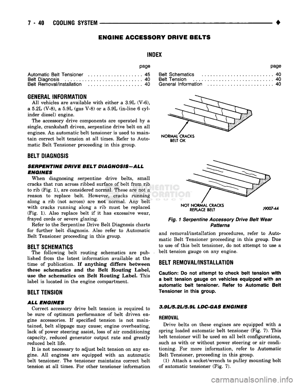
When diagnosing serpentine drive belts, small
cracks that run across ribbed surface of belt from rib
to rib (Fig. 1), are considered normal. These are not
a
reason
to
replace belt. However, cracks running along
a rib (not
across)
are not
normal.
Any
belt
with cracks running along
a rib
must
be
replaced (Fig.
1).
Also replace belt
if it has
excessive wear,
frayed cords
or
severe glazing.
Refer to the Serpentine Drive Belt Diagnosis charts
for further belt diagnosis. Also refer
to
Automatic Belt Tensioner proceeding
in
this group.
BELT SCHEMATICS
The following belt routing schematics
are
pub
lished from
the
latest information available
at the
time
of
publication.
If
anything differs between
these schematics
and the
Belt Routing Label,
use
the
schematics
on
Belt Routing Label. This
label
is
located
in
the engine compartment.
BELT TENSION
ALL
ENGINES
Correct accessory drive belt tension
is
required
to
be sure
of
optimum performance
of
belt driven
en
gine accessories.
If
specified tension
is not
main
tained, belt slippage may cause; engine overheating, lack
of
power steering assist, loss
of
air conditioning
capacity, reduced generator output rate and greatly
reduced belt life.
It
is
not necessary
to
adjust belt tension on any en
gine.
All
engines
are
equipped with
an
automatic
belt tensioner. The tensioner maintains correct belt tension
at all
times. For other tensioner information
NORMAL CRACKS
BELT
OK
NOT NORMAL CRACKS
REPLACE
BELT
J9007-44
Fig. 1 Serpentine Accessory Drive Belt Wear Patterns
and removal/installation procedures, refer
to
Auto
matic Belt Tensioner proceeding
in
this group.
Due
to use
of
this belt tensioner, do not attempt
to
use
a
belt tension gauge
on
any engine.
BELT REMOVAL/INSTALLATION
Caution:
Do not
attempt
to
check belt tension with
a
belt
tension gauge
on
vehicles equipped with
an
automatic belt tensioner. Refer
to
Automatic Belt
Tensioner
in
this
group.
3.9L/5,2U5*9L
LDC-GAS ENGINES
REMOVAL
Drive belts
on
these engines
are
equipped with
a
spring loaded automatic belt tensioner (Fig.
7).
This
belt tensioner will
be
used on
all
belt configurations, such
as
with
or
without power steering
or
air condi
tioning.
For
more information, refer
to
Automatic Belt Tensioner, proceeding
in
this group.
(1) Attach
a
socket/wrench
to
pulley mounting bolt
of automatic tensioner (Fig.
7).
Page 314 of 1502
•
*IF VEHICLE IS NOT EQUIPPED
WITH
POWER
STEERING,
THIS
WILL
BE
AN
IDLER PULLEY.
J9307-26
Fig.
2 Beit
Routing
- 3.9U5.2L/5.9L
LDC-Gas
Engine
AUTOMATIC TENSIONER
J9307-55
Fig.
3 Beit Routing—5.9L HDC-Gas Engine—With
A/C
(2)
Rotate tensioner assembly clockwise (as viewed
from front) until tension has been relieved from belt.
(3) Remove belt from idler pulley first.
(4)
Remove belt from vehicle.
INSTALLATION
CAUTION:
When
installing
serpentine accessory
drive
belt, belt
must
be
routed
correctly.
If not, en
gine
may
overheat
due to
water
pump
rotating in
COOLING
SYSTEM
7 - 43
AUTOMATIC TENSIONER
J9307-56
Fig.
4 Belt Routing—5.9L
HDC-Gas
Engine—Without A/C
'POWER STEERING PUMP IS
NOT
BELT DRIVEN
Fig.
5 Belt Routing-5.9L Diesel-With A/C
wrong
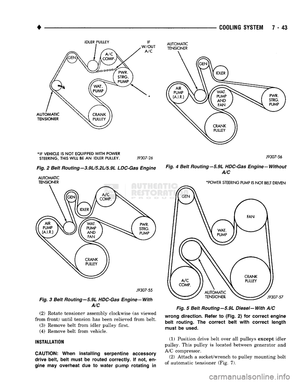
direction. Refer
to
(Fig.
2) for
correct engine
belt routing.
The
correct belt with correct length
must
be
used.
(1) Position drive belt over all pulleys except idler
pulley. This pulley is located between generator and
A/C compressor.
(2) Attach a socket/wrench to pulley mounting bolt
of automatic tensioner (Fig. 7).
Page 315 of 1502
7 - 44
COOLING
SYSTEM
•
Fig.
6 Belt Routing-5.9L Diesel-Without A/C
Fig.
7 Belt Tensioner-3.9L/5.2U5.9L
LDC-Gas
Engine
(3)
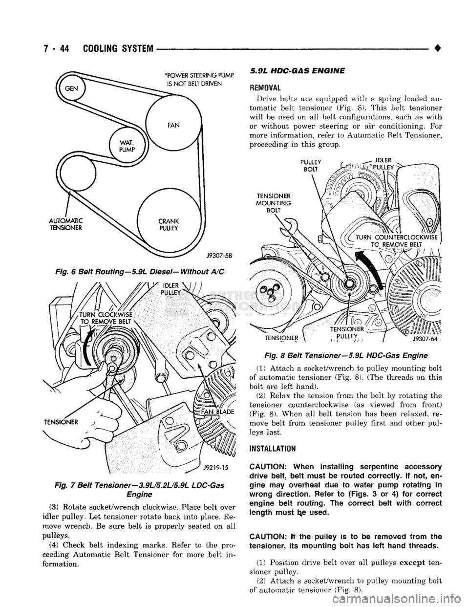
Rotate socket/wrench clockwise. Place belt over
idler pulley. Let tensioner rotate back into place. Re
move wrench. Be sure belt is properly seated on all
pulleys.
(4)
Check belt indexing marks. Refer to the pro
ceeding Automatic Belt Tensioner for more belt in
formation. 5.9L
HDC-GAS
ENGINE
REMOVAL
Drive belts are equipped with a spring loaded au
tomatic belt tensioner (Fig. 8). This belt tensioner
will be used on all belt configurations, such as with or without power steering or air conditioning. For
more information, refer to Automatic Belt Tensioner,
proceeding in this group.
Fig.
8 Belt Tensioner—5.9L
HDC-Gas Engine
(1) Attach a socket/wrench to pulley mounting bolt
of automatic tensioner (Fig. 8). (The threads on this
bolt are left hand).
(2) Relax the tension from the belt by rotating the
tensioner counterclockwise (as viewed from front) (Fig. 8). When all belt tension has been relaxed, re
move belt from tensioner pulley first and other pul leys last.
INSTALLATION
CAUTION:
When installing serpentine
accessory
drive belt, belt must
be
routed correctly.
If not, en
gine
may
overheat
due to
water pump rotating
in
wrong
direction. Refer
to
(Figs.
3 or 4) for
correct
engine
belt routing.
The
correct belt with correct length must
t^e
used.
CAUTION:
if the
pulley
is to be
removed from
the
tensioner,
its
mounting bolt
has left
hand threads.
(1) Position drive belt over all pulleys except ten
sioner pulley. (2) Attach a socket/wrench to pulley mounting bolt
of automatic tensioner (Fig. 8).