1993 DODGE TRUCK power steering
[x] Cancel search: power steeringPage 528 of 1502
WIRING
DIAGRAMS
8W - 53
-A21
14DB «• TO IGNITION
SWITCH
TRANSMISSION
(SEE
SH 10) CONTROL
SWITCH
FUSE
#2
(5 AMP)
65
20DB
E2
200R
i
TO ILLUM w
—j—
/ r
/
/
SPLICE
/
(SEE
SH 48) /
6
(SEE
SH
58)
-65
20DB/WT- (RIGHT OF
STEERING
COLUMN
ON I/P)
T6
200R/WT-
T61 20BK/0R"
T6
200R/WT-
T61 20BK/0R-
Zl 18BK-
L
— _ —
3_—
Zl 18BK-
-G5
20DB/WT
24
TO
SPLICE
(SEE
SH 48) T61
20BK
OR
•E2
200R
18
-UNG}-
. — , j
POWERTRAIN
10
CONTROL
MODULE
II 37
(PCM
II)
CONNECTOR
(SEE
SH 84)
55
T6 200R/WT-
•T61 20BK/0R-
54
—»-K54
200R/BK-
T0
SPLICE
T60 \S
200R
(SEE SH 16)
LG
44
T6
200R
WT
17
(ON
TRANSMISSION)
EMCC
SOLENOID •K54 20QR/BK
A21 14DB
-A21 14DB- •A21 14DB
-T60 200R/LG J
3.9L
TRANSMISSION
TROAVNEBn
5-9LENGINES overdrive system
(ON
TSSSION)
(AUTO/TRANSMISSION)
J938W-H
GAS MPI
ENGINES
-T60
200R/LG
TRANSMISSION-
OVERDRIVE
SOLENOID
AD
12
Page 530 of 1502
•
WIRING
DIAGRAMS
8W - 55
-A21 14DB (f
TO IGNITION
SWITCH
t
TRANSMISSION
(SEE
SH 10)
CONTROL
SWITCH
FUSE
#2
(5 AMP) 0 Q
V'
>S
(SEE
SH
58)
G5
20DB
WT -» G5 20DB/WT-
(RIGHT OF
STEERING
COLUMN
ON I/P)
T6 200R/WT-
T61 20BK/0R-
T6 200R/WT-
T61 20BK/0R-
3r—Ji
Zl 18BK- Zl 18BK-
-G5
20DB/WT 24
TO
(SEE
SH 48) T61
20BK
OR
c o
c o c)_p
I i
POWERTRAIN
CONTROL
10
MODULE
II q7 (PCM II) J/
CONNECTOR
(SEE
SH 83)
55 •T6 200R/WT-
•T61 20BK/0R- 44
T6
200R WT
T60
200R
LG
TO
SPLICE
(SEE
SH 24)
J938W-11
-A21 14DB-
DARK
GRAY
REAR
OF ENGINE)
T60 200R/LG
TRANSMISSION
OVERDRIVE
SYSTEM
DIESEL
ENGINES (PCM
TRANSMISSION-
OVERDRIVE
SOLENOID
II) AD 14
Page 548 of 1502
WIRING DIAGRAMS SW - 73
(RIGHT OF
STEERING
BLACK
(LEFT
REAR
FRAME
RAIL)
RESET
SWITCH DUMP SOL
#-/YYTP
i
ISO
SOL
DUAL SOLENOID
HYDRAULIC VALVE
BRAKE
WARNING LAMP SWITCH ;LEFT FRONT
FRAME
RAIL)
„ TO HAZARD
L50
18WT/TN
—(FLASHER SWITCH
(SEE
SH 56)
R.W.A.L.
SENSOR
(IN REAR DIFFERENTIAL) TO
POWERTRAIN
CONTROL
MODULE II CAVITY 29
(SEE
SH 35) O
STOP
LAMP AND VEHICLE
SPEED
CONTROL SWITCH
WITH
SPEED
CONTROL
STOP
LAMP SWITCH
WITHOUT
VEHICLE
SPEED
CONTROL
J938W-11
REAR
WHEEL ANTI-LOCK BRAKE SYSTEM
(GAS ENGINE) AD 32
Page 550 of 1502
WIRING
DIAGRAMS
8W - 75
Z8
18GY
PANEL
GROUND
Z09 18GY/BK
Bill
18LB -
_rrrRv_
(RIGHT 0F
~LL1U)
|
STEERING COLUMN)
(LEFT
REAR
FRAME
RAIL)
BLACK
B108 14WT/BR
-j=rf
B101 16LG/BK
-BLACK
18BK-
G11 18WT/BK
RESET
SWITCH
DUMP
ISO
SOL
BRAKE
WARNING
LAMP SWITCH
(LEFT
FRONT
FRAME
RAIL) DUAL SOLENOID
HYDRAULIC VALVE
GRAY
Gil
20WT
BK
BLUE
(LEFT
SIDE-UNDER INSTR/PANEL)
• • L50
18WT/TN
F32 20PK/DB
TO
BUZZER
(SEE
SH 77)
GROUND
SPLICE
(SEE
SH 48)
Bl13
18RD/VT
B114
18WT/VT
TO
HAZARD
L50
18WT/TN
?
FLASHER ^ SWITCH
(SEE
SH 56)
(TAPED
TO
HARNESS
NEAR
CONNECTOR) 8113
Bl14
18RD
18RD
VT
VT
F32 18PK/DB Zl
18BK 150
20WT/TN
Zl 20BK
V40
18WT/PK
TO
DATA LINK CONNECTOR
(SEE
SH 23)
RESISTOR
41
20PK
18WT V40
18WT
PK
i TO POWERTRAIN
CONTROL MODULE
II
CAVITY
29
(SEE
SH 37)
TWISTED
PAIR
BLACK
STOP
LAMP SWITCH
(LEFT FENDER
SIDE
SHIELD)
REAR WHEEL
ANT
I
-LOCK BRAKE SYSTEM
U938w-ii
(DIESEL ENGINE) R.W.A.L. SENSOR
(IN REAR DIFFERENTIAL)
AD
34
Page 591 of 1502
SW
- 116 WIRING DIAGRAMS
BLACK
P75
18DB/WT
P71 18YL
P73
18YL/PK
S23
18DB Sll
18WT
S13
18YL
LT HORIZONTAL
RT
UP DN
VERTICAL P74 18DB
Zl
12BK—'
Ml 18PK
BLACK
(RIGHT
OF STEERING COLUMN) P72
18YL/BK-
- P70 18WT - Zl
12BK Ml
20PK
Ml
18PK
Sll
18DG .Ml
(SEE
SH 49) P74
20DB/WT•
P72
20YL-
Ml Zl
20PK
12BK
TO
BATTERY FEED
(SEE
SH 3.5)
LEFT
MIRROR
MOTORS
T FUSE #15
(10 AMP)
•A4 14BK/RD TO
(SEE
SH 48) AD 75
POWER MIRRORS
J938W-11
Page 625 of 1502
TRANSFER
CASE
INSULATOR
MOUNTING PLATE
NUT(B
RAIL
ASSEMBLY
SPACER
UPPER
INSULATOR
NUT®
LOWER
INSULATOR
J9109-242
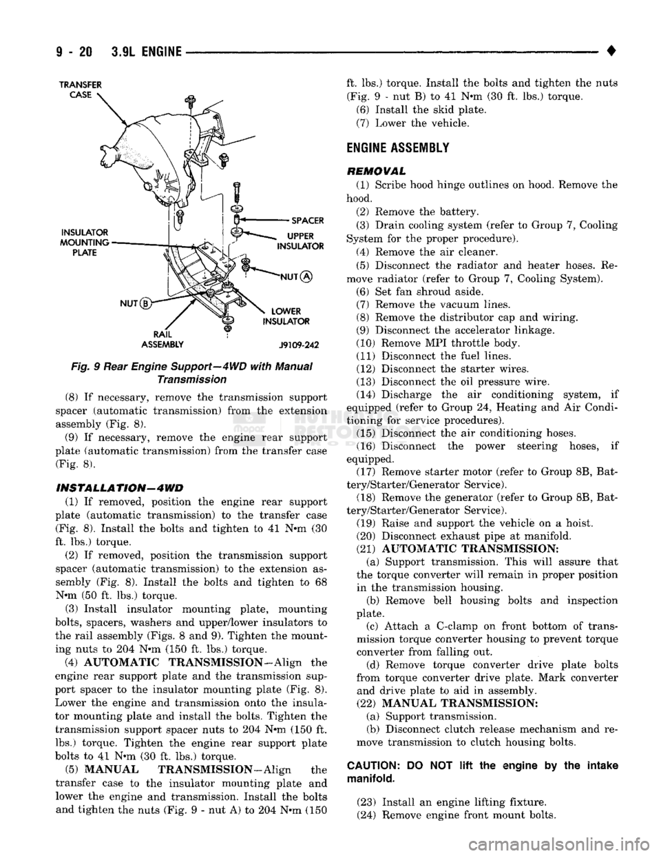
Fig.
9 Rear
Engine
Support—4WD
with
Manual
Transmission
(8) If necessary, remove the transmission support
spacer (automatic transmission) from the extension
assembly (Fig. 8).
(9) If necessary, remove the engine rear support
plate (automatic transmission) from the transfer case (Fig. 8).
INSTALLATION-4WD
(1) If removed, position the engine rear support
plate (automatic transmission) to the transfer case (Fig. 8). Install the bolts and tighten to 41 N-m (30
ft. lbs.) torque.
(2) If removed, position the transmission support
spacer (automatic transmission) to the extension as
sembly (Fig. 8). Install the bolts and tighten to 68 N-m (50 ft. lbs.) torque.
(3) Install insulator mounting plate, mounting
bolts,
spacers, washers and upper/lower insulators to
the rail assembly (Figs. 8 and 9). Tighten the mount
ing nuts to 204 N*m (150 ft. lbs.) torque.
(4) AUTOMATIC TRANSMISSION-Align the
engine rear support plate and the transmission sup
port spacer to the insulator mounting plate (Fig. 8). Lower the engine and transmission onto the insula
tor mounting plate and install the bolts. Tighten the transmission support spacer nuts to 204 N-m (150 ft. lbs.) torque. Tighten the engine rear support plate
bolts to 41 N-m (30 ft. lbs.) torque.
(5) MANUAL TRANSMISSION—Align the
transfer case to the insulator mounting plate and lower the engine and transmission. Install the bolts and tighten the nuts (Fig. 9 - nut A) to 204 N-m (150 ft. lbs.) torque. Install the bolts and tighten the nuts
(Fig. 9 - nut B) to 41 N-m (30 ft. lbs.) torque. (6) Install the skid plate.
(7) Lower the vehicle.
ENGINE
ASSEMBLY
REMOVAL (1) Scribe hood hinge outlines on hood. Remove the
hood.
(2) Remove the battery. (3) Drain cooling system (refer to Group 7, Cooling
System for the proper procedure).
(4) Remove the air cleaner. (5) Disconnect the radiator and heater hoses. Re
move radiator (refer to Group 7, Cooling System).
(6) Set fan shroud aside. (7) Remove the vacuum lines. (8) Remove the distributor cap and wiring.
(9) Disconnect the accelerator linkage.
(10) Remove MPI throttle body. (11) Disconnect the fuel lines. (12) Disconnect the starter wires.
(13) Disconnect the oil pressure wire. (14) Discharge the air conditioning system, if
equipped (refer to Group 24, Heating and Air Condi
tioning for service procedures). (15) Disconnect the air conditioning hoses.
(16) Disconnect the power steering hoses, if
equipped. (17) Remove starter motor (refer to Group 8B, Bat
tery/Starter/Generator Service). (18) Remove the generator (refer to Group 8B, Bat
tery/Starter/Generator Service).
(19) Raise and support the vehicle on a hoist.
(20) Disconnect exhaust pipe at manifold.
(21) AUTOMATIC TRANSMISSION: (a) Support transmission. This will assure that
the torque converter will remain in proper position in the transmission housing. (b) Remove bell housing bolts and inspection
plate.
(c) Attach a C-clamp on front bottom of trans
mission torque converter housing to prevent torque
converter from falling out.
(d) Remove torque converter drive plate bolts
from torque converter drive plate. Mark converter and drive plate to aid in assembly.
(22) MANUAL TRANSMISSION: (a) Support transmission.
(b) Disconnect clutch release mechanism and re
move transmission to clutch housing bolts.
CAUTION:
DO NOT
lift
the engine by the intake
manifold.
(23) Install an engine lifting fixture.
(24) Remove engine front mount bolts.
Page 626 of 1502
•
3.9L
ENGINE
9 - 21 (25) Lower the vehicle.
(26) On automatic transmission vehicles, discon
nect the engine from the torque converter drive
plate. On manual transmission vehicles, move engine forward until drive pinion shaft clears the clutch
disc.
Remove engine from engine compartment. (27) Install engine assembly on engine repair
stand.
INSTALLATION (1) Remove engine from the repair stand and posi
tion in the engine compartment.
(2) Install engine support fixture.
(3) Raise and support the vehicle on a hoist.
(4)
AUTOMATIC TRANSMISSION: (a) Position the torque converter and drive plate.
Install torque converter drive plate bolts. Tighten
the bolts to 31 Nnn (270 in. lbs.) torque.
(b) Install the engine front mounts.
(c) Install bell housing bolts. Tighten the bolts to
41 N-m (30 ft. lbs.) torque.
(d) Remove C-clamp.
(e) Install the inspection plate.
(5) MANUAL TRANSMISSION: (a) Position the drive pinion shaft to the clutch
disc.
(b) Connect the clutch release mechanism and
install the transmission to clutch bolts. Tighten the
bolts to 68 N-m (50 ft. lbs.) torque.
(c) Install the engine front mounts.
(6) Remove transmission support.
(7) Install exhaust pipe to manifold.
(8) Lower the vehicle.
(9) Remove engine lifting fixture.
(10) Install the generator (refer to Group 8B, Bat
tery/Starter/Generator Service). (11) Install starter motor (refer to Group 8B, Bat
tery/Starter/Generator Service). (12) Connect power steering hoses, if equipped.
(13) Connect air conditioning hoses.
(14) Evacuate and charge the air conditioning sys
tem, if equipped (refer to Group 24, Heater and Air Conditioning for service procedures). (15) Using a new gasket, install MPI throttle body.
Tighten the throttle body bolts to 23 N-m (200 in. lbs.) torque. (16) Connect the accelerator linkage.
(17) Connect the starter wires. (18) Connect the oil pressure wire.
(19) Install the distributor cap and wiring.
(20) Connect the vacuum lines.
(21) Connect the fuel lines.
(22) Install the radiator (refer to Group 7, Cooling
System). Connect the radiator hoses and heater
hoses.
(23) Install fan shroud in position. (24) Fill cooling system (refer to Group 7, Cooling
System for the proper procedures). (25) Install the air cleaner.
(26) Install the battery.
(27) Warm engine and adjust.
(28) Install hood and line up with the scribe
marks. (29) Road test vehicle.
CYLINDER
HEAD COVER
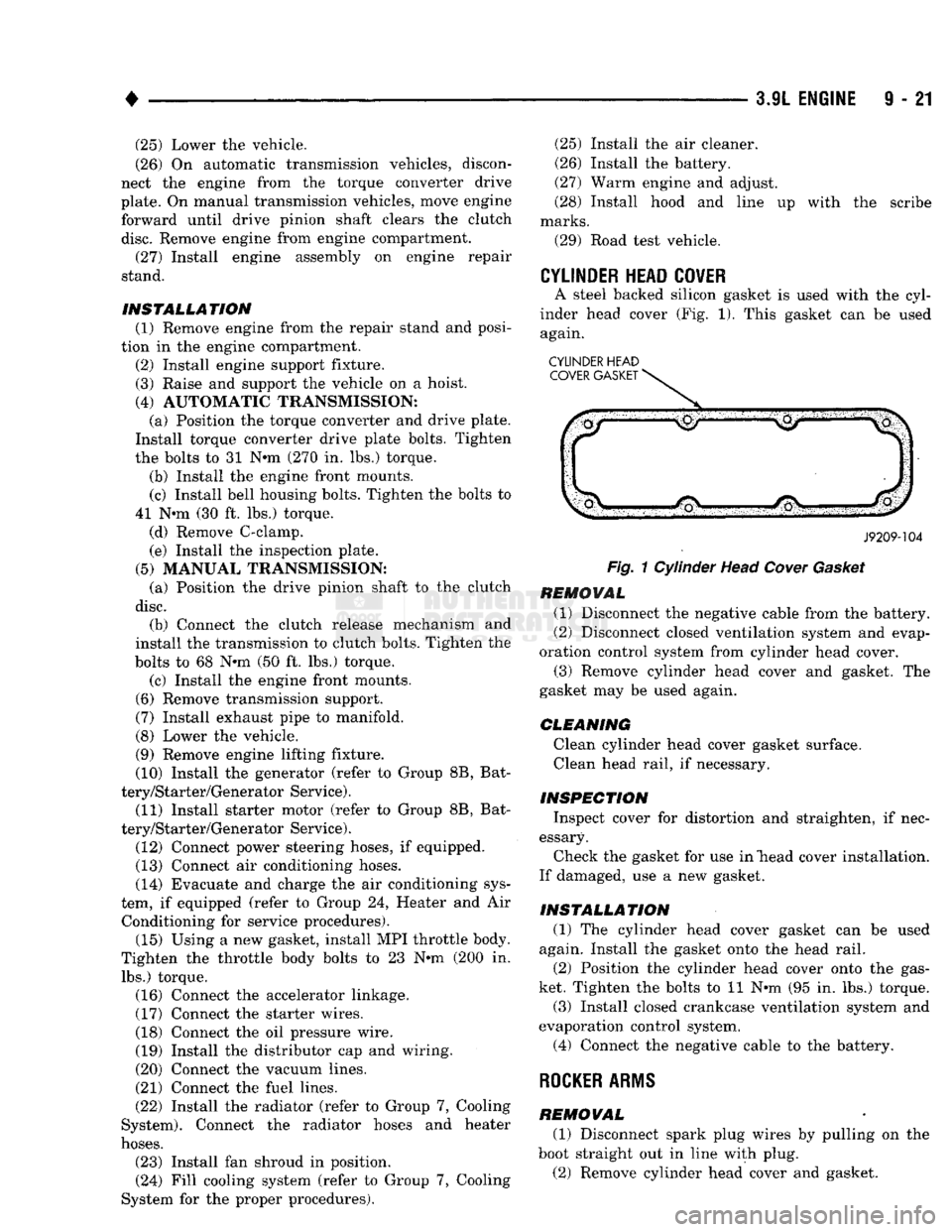
A steel backed silicon gasket is used with the cyl
inder head cover (Fig. 1). This gasket can be used again.
CYLINDER HEAD COVER GASKET
J9209-104
Fig.
1 Cylinder Head
Cover
Gasket
REMOVAL (1) Disconnect the negative cable from the battery.
(2) Disconnect closed ventilation system and evap
oration control system from cylinder head cover. (3) Remove cylinder head cover and gasket. The
gasket may be used again.
CLEANING Clean cylinder head cover gasket surface. Clean head rail, if necessary.
INSPECTION Inspect cover for distortion and straighten, if nec
essary. Check the gasket for use in "head cover installation.
If damaged, use a new gasket.
INSTALLATION (1) The cylinder head cover gasket can be used
again. Install the gasket onto the head rail.
(2) Position the cylinder head cover onto the gas
ket. Tighten the bolts to 11 N-m (95 in. lbs.) torque. (3) Install closed crankcase ventilation system and
evaporation control system.
(4) Connect the negative cable to the battery.
ROCKER
ARMS
REMOVAL (1) Disconnect spark plug wires by pulling on the
boot straight out in line with plug.
(2) Remove cylinder head cover and gasket.
Page 634 of 1502
•
3.9L
ENGINE
I - 21
VIBRATION
DAMPER
REMOVAL
(1) Disconnect the negative cable from the battery,
(2) Remove fan shroud retainer bolts and set
shroud back over engine.
(3) Remove the cooling system fan.
(4) Remove the serpentine belt (refer to Group 7,
Cooling System).
(5) Remove the vibration damper pulley.
(6) Remove vibration damper bolt and washer from
end of crankshaft.
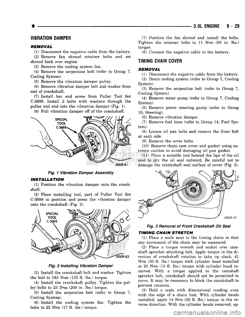
(7) Install bar and screw from Puller Tool Set
C-3688.
Install 2 bolts with washers through the
puller tool and into the vibration damper (Fig. 1).
(8) Pull vibration damper off of the crankshaft.
J9209-81
Fig. 1 Vibration
Damper
Assembly INSTALLATION
(1) Position the vibration damper onto the crank
shaft.
(2) Place installing tool, part of Puller Tool Set
C-3688 in position and press the vibration damper
onto the crankshaft (Fig. 2).
Fig. 2 Installing Vibration Damper
(3) Install the crankshaft bolt and washer. Tighten
the bolt to 183 N*m (135 ft. lbs.) torque.
(4) Install the crankshaft pulley. Tighten the pul
ley bolts to 23 N*m (200 in. lbs.) torque.
(5) Install the serpentine belt (refer to Group 7,
Cooling System).
(6) Install the cooling system fan. Tighten the
bolts to 23 N*m (17 ft. lbs.) torque. (7) Position the fan shroud and install the bolts.
Tighten the retainer bolts to 11 N*m (95 in. lbs.)
torque.
(3)
Connect the negative cable to the battery.
TIMING CHAIN
COVER
REMOVAL (1)
Disconnect the negative cable from the battery.
(2)
Drain cooling system (refer to Group 7, Cooling
System).
(3)
Remove the serpentine belt (refer to Group 7,
Cooling System).
(4)
Remove water pump (refer to Group 7, Cooling
System).
(5)
Remove power steering pump (refer to Group
19,
Steering).
(6)
Remove vibration damper. (7) Remove fuel lines (refer to Group 14, Fuel Sys
tem).
(8) Loosen oil pan bolts and remove the front bolt
at each side.
(9)
Remove the cover bolts.
(10)
Remove chain case cover and gasket using ex
treme caution to avoid damaging oil pan gasket.
(11)
Place a suitable tool behind the lips of the oil
seal to pry the oil seal outward. Be careful not to
damage the crankshaft seal surface of cover (Fig. 3). Fig. 3 Removal of Front Crankshaft Oil Seal
TIMING CHAIN STRETCH
(1) Place a scale next to the timing chain so that
any movement of the chain may be measured.
(2)
Place a torque wrench and socket over cam
shaft sprocket attaching bolt. Apply torque in the di
rection of crankshaft rotation to take up slack; 41
N#m (30 ft. lbs.) torque with cylinder head installed or 20 N»m (15 ft. lbs.) torque with cylinder head re
moved. With a torque applied to the camshaft sprocket bolt, crankshaft should not be permitted to
move. It may be necessary to block the crankshaft to
prevent rotation.
(3)
Hold a scale with dimensional reading even
with the edge of a chain link. With cylinder heads installed, apply 14 N*m (30 ft. lbs.) torque in the re
verse direction. With the cylinder heads removed, ap-