1993 DODGE TRUCK tailgate
[x] Cancel search: tailgatePage 9 of 1502
4 INTRODUCTION
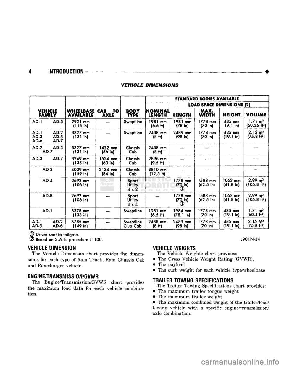
• VEHICLE DIMENSIONS
VEHICLE
FAMILY
WHEELBASE
AVAILABLE
CAB
TO
AXLE BODY
TYPE
SfANDAID
SODIES
AVAILABLE
VEHICLE
FAMILY
WHEELBASE
AVAILABLE
CAB
TO
AXLE BODY
TYPE
NOMINAL
LENGTH
(LOAD
SPACE
D
MENSIONS
(2)
VEHICLE
FAMILY
WHEELBASE
AVAILABLE
CAB
TO
AXLE BODY
TYPE
NOMINAL
LENGTH LENGTH MAX.
WIDTH
HEIGHT
VOLUME
AD-1
AD-5
2921
mm
(115
in) —
Sweptline
1981
mm
(6.5
ft)
1981
mm
(78
in)
1778 mm
(70
in)
485 mm
19.1
in) 1.71 m3
(60.35
ft3)
AD-1
AD-2
AD-3
AD-5
AD-6
AD-7
3327
mm
(131
in) —
Sweptline
2438 mm
(8
ft)
2489 mm
(98
in)
1778 mm
(70
in)
485 mm
(19.1
in)
2.15
m3
(75.8
ft3)
AD-2
AD-3
AD-7
3327
mm
(131
in)
1422 mm
(56
in)
Chassis
Cab
2438 mm
(8
ft)
—
— — —
AD-3
AD-7
3249 mm
(135
in)
1524 mm
(60
in)
Chassis
Cab
2896 mm
(9.5
ft) —
— — —
AD-3
4039 mm
(159
in)
2134 mm
(84
in)
Chassis
Cab
3810 mm
(12.5
ft)
—
— —
AD-4
2692
mm
(106
in)
Sport
Utility
4x2
—
1778 mm 1588 mm
(62.5
in)
1062 mm
(41.8
in)
2.99
m3
(105.8
ft3)
AD-8
2692
mm
(106
in)
Sport
Utility
4x4
—
1778 mm 1588 mm
(62.5
in)
1062 mm
(41.8
in)
2.99
m3
(105.8
ft3)
AD-1
3378 mm
(133
in) —
Sweptline
1981
mm
(6.5
ft)
1984 mm
(78.1
in)
1778 mm
(70
in)
485 mm
(19.1
in) 1.71 m3
(60.4
ft3)
AD-1
AD-2
AD-5
AD-6
3785 mm
(149
in) —
Sweptline
Club
Cab 2438 mm
(8
ft)
2489 mm
(98
in)
1778 mm
(70
in)
485 mm
(19.1
in)
2.15
M3
(75.8
ft3)
®
Driver seat
to
tailgate.
(2)
Based
on
S.A.E.
procedure
Jl
100. J901N-34
VEHICLE
WEIGHTS
The Vehicle Weights chart provides:
• The Gross Vehicle Weight Rating (GVWR),
• The payload
• The curb weight
for
each vehicle type/wheelbase
TRAILER
TOWING
SPECIFICATIONS
The Trailer Towing Specifications chart provides:
• The maximum trailer tongue weight
• The maximum trailer weight
• The maximum combined weight of the trailer/load/
towing vehicle with
a
specific engine/transmission/ axle combination.
VEHICLE
DIMENSION
The Vehicle Dimension chart provides
the
dimen
sions
for
each type
of
Ram Truck, Ram Chassis Cab
and Ramcharger vehicle.
ENGINE/TRANSMISSION/GVWR
The Engine/Transmission/GVWR chart provides
the maximum load data
for
each vehicle combina tion.
Page 52 of 1502
•
LUBRICATION
AND
MAINTENANCE
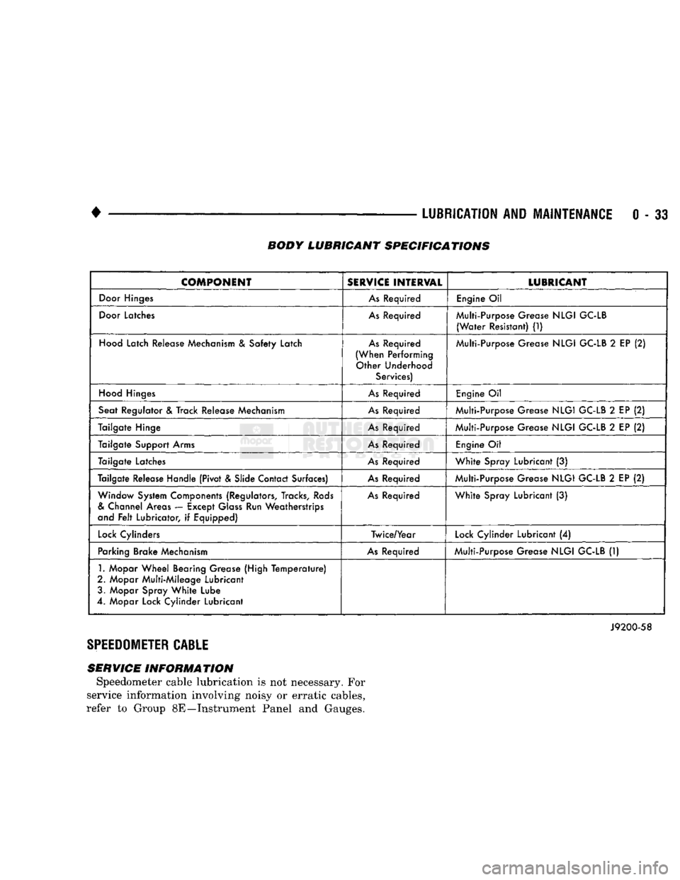
0 - 33 BODY LUBRICANT SPECIFICATIONS
COMPONENT
SERVICE
INTERVAL
LUBRICANT
Door
Hinges
As
Required
Engine
Oil
Door
Latches
As
Required Multi-Purpose Grease
NLGI
GC-LB
(Water
Resistant)
(1)
Hood
Latch Release Mechanism
&
Safety Latch
As
Required
(When Performing Other Underhood Services) Multi-Purpose Grease
NLGI
GC-LB
2
EP
(2)
Hood
Hinges
As
Required
Engine
Oil
Seat Regulator
&
Track Release Mechanism
As
Required Multi-Purpose Grease
NLGI
GC-LB
2
EP
(2)
Tailgate Hinge
As
Required Multi-Purpose Grease
NLGI
GC-LB
2
EP
(2)
Tailgate Support Arms
As
Required
Engine
Oil
Tailgate Latches
As
Required
White
Spray Lubricant
(3)
Tailgate Release Handle (Pivot & Slide Contact Surfaces)
As
Required Multi-Purpose Grease
NLGI
GC-LB
2
EP
(2)
Window System Components (Regulators, Tracks,
Rods
&
Channel Areas — Except
Glass
Run Weatherstrips
and
Felt
Lubricator,
if
Equipped)
As
Required
White
Spray Lubricant
(3)
Lock
Cylinders Twice/Year
Lock
Cylinder Lubricant
(4)
Parking Brake Mechanism
As
Required Multi-Purpose Grease
NLGI
GC-LB
(1)
1.
Mopar
Wheel
Bearing Grease (High
Temperature)
2. Mopar Multi-Mileage Lubricant 3. Mopar Spray
White
Lube
4. Mopar Lock Cylinder Lubricant
J9200-58
SPEEDOMETER
CABLE
SERVICE INFORMATION Speedometer cable lubrication is not necessary. For
service information involving noisy or erratic cables,
refer to Group 8E—Instrument Panel and Gauges.
Page 448 of 1502
•
LAMPS
8L - 5
J918L-27
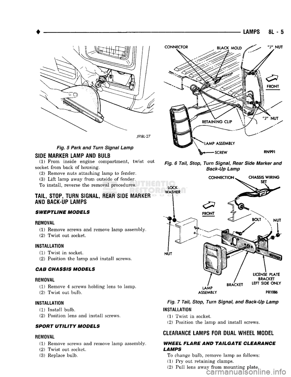
Fig.
5
Park
and Turn
Signal
Lamp
SIDE MARKER LAMP AND BULB
(1) From inside engine compartment, twist out
socket from back of housing. (2) Remove nuts attaching lamp to fender. (3) Lift lamp away from outside of fender.
To install, reverse the removal procedures.
TAIL,
STOP, TURN
SIGNAL,
REAR SIDE MARKER
AND BACK-UP LAMPS
SWEPTLINE MODELS
REMOVAL
(1) Remove screws and remove lamp assembly.
(2) Twist out socket.
INSTALLATION (1) Twist in socket.
(2) Position the lamp and install screws.
CAB CHASSIS MODELS
REMOVAL (1) Remove 4 screws holding lens to lamp. (2) Twist out bulb.
INSTALLATION (1) Install bulb.
(2) Position lens and install screws.
SPORT UTILITY MODELS
REMOVAL
(1) Remove screws and remove lamp assembly.
(2) Twist out socket. (3) Replace bulb.
Fig.
6
Tail,
Stop,
Turn
Signal,
Rear
Side
Marker and
Back-Up
Lamp
LAMP
ASSEMBLY
PR1086
Fig.
7
Tail,
Stop,
Turn
Signal,
and
Back-Up
Lamp
INSTALLATION
(1) Twist in socket. (2) Position the lamp and install screws.
CLEARANCE LAMPS
FOR
DUAL WHEEL MODEL
WHEEL FLARE AND TAILGATE CLEARANCE
LAMPS
To change bulb, remove lamp as follows: (1) Pry out retaining clamps.
(2) Pull lens away from mounting plate.
Page 482 of 1502
CAVITY
FUSE/
COLOR ITEMS FUSED
CAVITY
FUSE/
COLOR ITEMS FUSED
10
11
12
13 2 AMP
GY VEHICLE SPEED CONTROL
5 AMP TN
GAUGES,
BRAKE WARNING LAMP, SEAT BELT WARNING
LAMP, BUZZER, LOW OIL LAMP, CHECK ENGINE LAMP,
ANTI-LOCK LAMP, TAILGATE OPEN LAMP, 4WD LAMP, O/D MODULE, LOW FUEL LAMP,
WAIT
TO START LAMP
WATER-IN-FUEL LAMP 14
3 AMP
VT
20 AMP YL BACK-UP LAMP, HEATED REAR WINDOW
15 10 AMP
RD
ILLUMINATION
LAMPS, A/C HEATER LAMP, ASH
RECEIVER LAMP, RADIO LAMP, TRANSMISSION
OVERDRIVE SWITCH LAMP, TACHOMETER LAMP, HEATED REAR WINDOW SWITCH LAMP.
RADIO AND CLOCK MEMORY, POWER MIRRORS, GLOVE BOX LAMP, DOME LAMP, READING LAMP, MAP LAMP,
CARGO LAMP,
IGNITION
SWITCH LAMP, UNDERHOOD LAMP
20 AMP YL FUSE CAVITY #14,
TAIL
LAMPS, PARKING LAMPS, SIDE
AAARKER
LAMPS, LICENSE LAMPS, FRONT AND REAR CLEARANCE LAMPS, RADIO INTENSITY, HORNS
20 AMP YL STOP LAMPS, KEY-IN & HEADLAMP ON BUZZER, RWAL
MODULE 30 AMP
CIRCUIT
BREAKER
TURN
SIGNAL
FLASHER 20 AMP
YL POWER DOOR LOCKS
15 AMP
BL
CIGAR LIGHTER
10 AMP RD RADIO AND CLOCK
20 AMP YL
TURN
SIGNALS, TACHOMETER PROVISION,
RWAL MODULE
20 AMP YL WINDSHIELD WIPERS
30 AMP LG A/C - HEATER BLOWER MOTOR
30 AMP
C/BRKR
POWER WINDOWS
20 AMP YL HAZARD FLASHER
AMPS
FUSE
COLOR
2 GY GRAY
3 VT
VIOLET
5 TN
TAN
10 RD
RED
15
BL
BLUE
20 YL YELLOW
30 LG
LIGHT
GREEN HAZARD
FLASHER
J938W-94
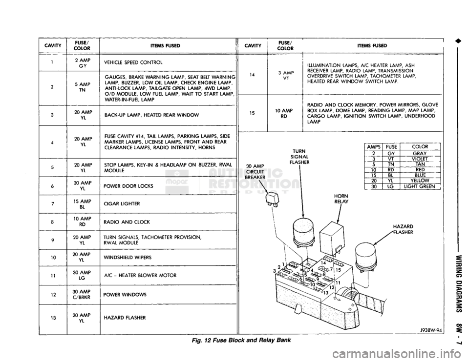
Fig. 12 Fuse Block and
Relay
Bank
Page 1384 of 1502
•
BODY
COMPONENTS
23 - 1
CONTENTS
page
page
CAB/BODY
INTERIOR COMPONENTS
35
FIXED
GLASS
. 29
DOORS
21
PAINT
CODE
CHART
54
EXTERIOR
COMPONENTS
1
REFINISHING
PROCEDURES
54
EXTERIOR COMPONENTS
INDEX
page
Battery
Tray
7
Blower Motor Housing
Insulation
Panel—Diesel
Engine
Only
7
Body
Mouldings, Nameplates
and
Decals .......
9
Cab
. 14
Cab/Body
and
Cargo
Box
Stripes
11
Cargo
Box
19
Cowl
Grille
7
Front
Fenders
8
Fuel
Filler
Door
and
Nozzle/Tubes
12
Grille
and
Grille
Extension Panel
1
Grille
Extension Panel Support Bracket
(With
Diesel Engine Only)
3
page
Grille
Opening Panel (GOP)
and
Radiator Support Panel
3
Hatchgate
and
Components
16
Hood
5
Hood
Inside Release Cable
5
Hood
Latch
4
Labels/Decals/Plates
1
Outside Mirrors
13
Roof
Vent—Ramcharger
. 20
Splash
Shields—Front Fender
9
Sport
Bar
18
Tailgate
14
LABELS/DECALS/PLATES
GENERAL
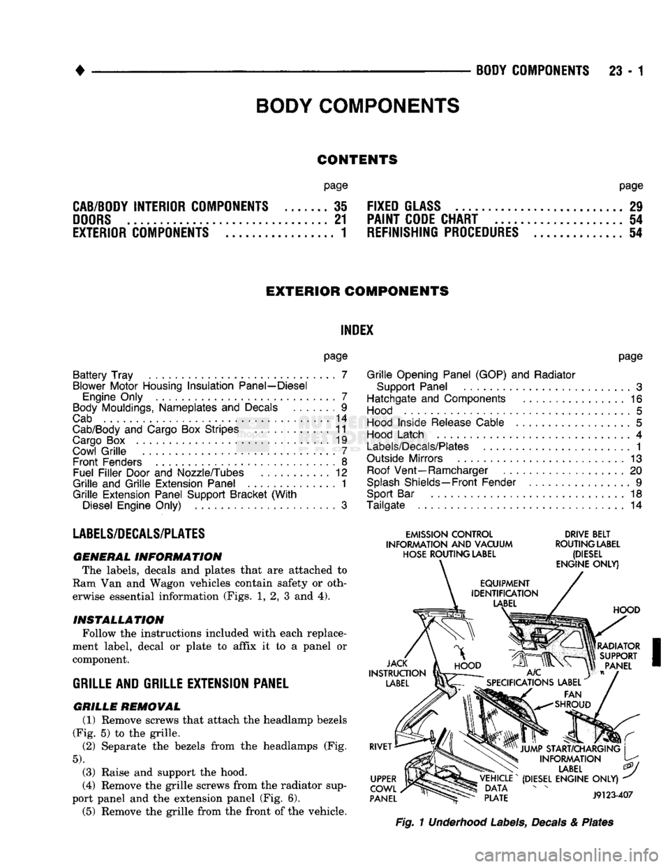
INFORMATION The labels, decals
and
plates that
are
attached
to
Ram Van
and
Wagon vehicles contain safety
or
oth erwise essential information (Figs.
1, 2, 3 and 4).
INSTALLATION
Follow the instructions included with each replace
ment label, decal
or
plate
to
affix
it to a
panel
or
component.
GRILLE
AND GRILLE EXTENSION PANEL
GRILLE
REMOVAL (1) Remove screws that attach the headlamp bezels
(Fig.
5) to the
grille.
(2)
Separate
the
bezels from
the
headlamps
(Fig.
5).
(3) Raise
and
support
the
hood.
(4) Remove the grille screws from the radiator sup
port panel
and the
extension panel (Fig.
6).
(5) Remove
the
grille from the front
of
the vehicle.
EMISSION
CONTROL
DRIVE
BELT
INFORMATION
AND
VACUUM
ROUTING
LABEL
HOSE
ROUTING
LABEL
(DIESEL
Fig.
1 Underhood Labels, Decals & Plates
BODY
COMPONENTS
Page 1393 of 1502
23-10 BODY COMPONENTS
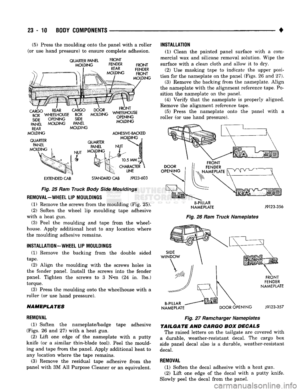
(5) Press the moulding onto the panel with a roller
(or use hand pressure) to ensure complete adhesion.
QUARTER PANEL
MOLDING
FRONT
FENDER
REAR
MOLDING
FRONT
FENDER
FRONT
MOLDING
REAR
CARGO
DOOR
FRONT
^WHEEWOUSE
~SST
MSSNG
W^|S$E
SIDE
OPENING
SIDE
PANEL
MOLDING
PANEL
REAR
MOLDING
MOLDING
QUARTER PANEL
MOLDING
OPENING
MOLDING
ADHESIVE-BACKED
MOLDING
NUT QUARTER
PANEL
MOLDING
EXTENDED
CAB
STANDARD
CAB
10.5
MMlyx
CHARACTER
UNE
J9123-603
Fig.
25 Ram Truck
Body
Side
Mouldings
REMOVAL—WHEEL
LIP MOULDINGS (1) Remove the screws from the moulding (Fig. 25).
(2) Soften the wheel lip moulding tape adhesive
with a heat gun.
(3) Peel the moulding and tape from the wheel-
house. Apply additional heat to any location where
the moulding adhesive remains.
INSTALLATION—WHEEL LIP MOULDINGS (1) Remove the backing from the double sided
tape.
(2) Align the moulding with the screws holes in
the fender panel. Install the screws into the fender
panel. Tighten the screws to 3 N*m (24 in. lbs.)
torque.
(3) Press the moulding onto the wheelhouse with a
roller (or use hand pressure).
NAMEPLATES
REMOVAL
(1) Soften the nameplate/badge tape adhesive
(Figs.
26 and 27) with a heat gun. (2) Lift one edge of the nameplate with a putty
knife (or a similar thin-blade tool). Peel the mould
ing and tape from the panel. Apply additional heat to any location where the tape remains.
(3) Remove the residual tape adhesive from the
panel with 3M All Purpose Cleaner or an equivalent. INSTALLATION
(1) Clean the painted panel surface with a com
mercial wax and silicone removal solution. Wipe the
surface with a clean cloth and allow it to dry.
(2) Use masking tape to indicate the upper posi
tion for the nameplate on the panel (Figs. 26 and 27).
(3) Remove the backing from the nameplate. Align
the nameplate with the alignment reference tape. Po sition the nameplate on the panel. (4) Verify that the nameplate is properly aligned.
Remove the alignment reference tape. (5) Press the nameplate onto the panel with a
roller (or use hand pressure).
DOOR
OPENING
B-PILLAR
NAMEPLATE
J9123-356
Fig.
26 Ram Truck Nameplates
SIDE
WINDOW
B-PILLAR
NAMEPLATE
DOOR
OPENING
FRONT
FENDER
NAMEPLATE
J9123-357
Fig.
27
Ramcharger
Nameplates
TAILGATE
AND
CARGO
BOM
DECALS
The raised letters on the tailgate are covered with
a durable, weather-resistant decal. The cargo box
side panel decal also is a durable, weather-resistant
decal.
REMOVAL
(1) Soften the decal adhesive with a heat gun.
(2) Lift one edge of the decal with a putty knife.
Slowly peel the decal from the panel.
Page 1394 of 1502
•
BODY COMPONENTS
23 - 11 (3) Apply additional heat to any location where the
decal remains adhered to the panel.
(4) Remove the extra adhesive from the panel with
a cloth saturated with an adhesive remover.
INSTALLATION
(1) Clean the panel surface with a commercial wax
and silicone removal solution. Wipe the surface with
a clean cloth. (2) Remove the backing from the decal. Position it
on the panel.
(3) Verify that the decal is properly aligned.
(4) Press the decal onto the panel with a roller to
ensure complete adhesion.
Fig.
28
Tailgate
&
Cargo
Box
Decals
TMILGA
TE/HA
TCHGA
TE
APPLIQUE
REMOVAL
(1) Open the tailgate/hatchgate.
(2) If applicable, remove the hatchgate trim panel.
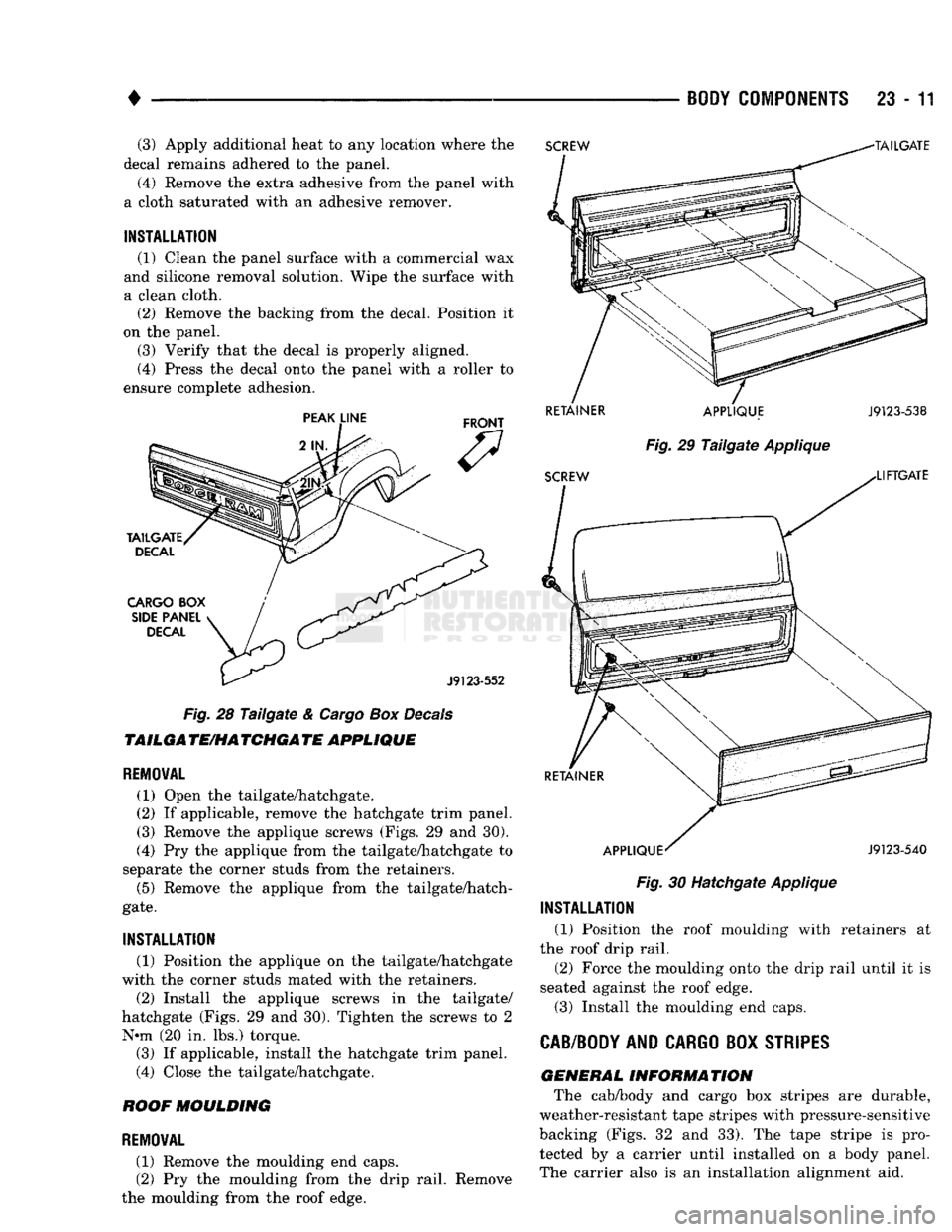
(3) Remove the applique screws (Figs. 29 and 30).
(4) Pry the applique from the tailgate/hatchgate to
separate the corner studs from the retainers. (5) Remove the applique from the tailgate/hatch
gate.
INSTALLATION
(1) Position the applique on the tailgate/hatchgate
with the corner studs mated with the retainers.
(2) Install the applique screws in the tailgate/
hatchgate (Figs. 29 and 30). Tighten the screws to 2 N-m (20 in. lbs.) torque. (3) If applicable, install the hatchgate trim panel.
(4) Close the tailgate/hatchgate.
ROOF
MOULDING
REMOVAL
(1) Remove the moulding end caps.
(2) Pry the moulding from the drip rail. Remove
the moulding from the roof edge.
RETAINER
APPLIQUE
J9123-538
Fig.
29
Tailgate
Applique
Fig.
30 Hatchgate Applique
INSTALLATION
(1) Position the roof moulding with retainers at
the roof drip rail. (2) Force the moulding onto the drip rail until it is
seated against the roof edge.
(3) Install the moulding end caps.
CAB/BODY
AND
CARGO
BOX
STRIPES
GENERAL
INFORMATION
The cab/body and cargo box stripes are durable,
weather-resistant tape stripes with pressure-sensitive
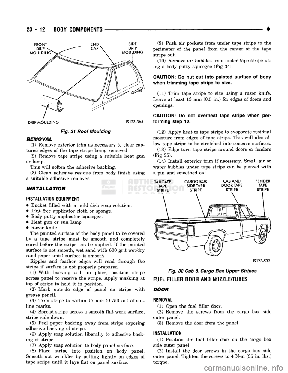
backing (Figs. 32 and 33). The tape stripe is pro tected by a carrier until installed on a body panel.
The carrier also is an installation alignment aid.
Page 1395 of 1502
23
- 12
BODY COMPONENTS
•
Fig.
31
Roof
Moulding
REMOVAL
(1) Remove exterior trim as necessary to clear cap
tured edges of the tape stripe being removed
(2) Remove tape stripe using a suitable heat gun
or lamp. This will soften the adhesive backing.
(3) Clean adhesive residue from body finish using
a suitable adhesive remover.
INSTALLATION
INSTALLATION EQUIPMENT
• Bucket filled with a mild dish soap solution.
• Lint free applicator cloth or sponge. • Body putty applicator squeegee.
• Heat gun or sun lamp.
• Razor knife.
The painted surface of the body panel to be covered
by a tape stripe must be smooth and completely cured before the stripe can be applied. If the painted surface is not smooth, wet sand with 600 grit wet/dry
sand paper until surface is smooth.
Ripples and feather edges will read through the
stripe if surface is not properly prepared. (1) With backing still in place, position stripe
across panel to receive the stripe. Apply masking at
top of stripe to hold it in position. (2) Mark outside edge of panel on stripe with
grease pencil. (3) Trim stripe to within 17 mm (0.750 in.) of out
line marks.
(4) Spread stripe across a smooth flat work surface,
stripe side down. (5) Peel paper backing away from stripe exposing
adhesive backing of stripe.
(6) Apply soap solution liberally to adhesive back
ing of stripe. (7) Apply soap solution to body panel surface.
(8) Place stripe into position on body panel.
Smooth out wrinkles by pulling lightly on edges of
tape stripe until it lays flat on panel surface. (9) Push air pockets from under tape stripe to the
perimeter of the panel from the center of the tape stripe out. (10) Remove air bubbles from under tape stripe us
ing a body putty squeegee (Fig 34).
CAUTION:
Do nut cut
Into
painted surface
of body
when trimming
tape
stripe
to
size.
(11) Trim tape stripe to size using a razor knife.
Leave at least 13 mm (0.5 in.) for edges of doors and openings.
CAUTION;
Do not overheat
tape
stripe
when
per
forming
step
12.
(12) Apply heat to tape stripe to evaporate residual
moisture from edges of tape stripe. This will also al
low tape stripe to be stretched into concave surfaces.
(13) Edge turn tape stripe around doors or fenders
(Fig 35). (14) Install exterior trim if necessary. Small air or
water bubbles under tape stripe can be pierced with a pin and smoothed out.
TAILGATE
CARGO BOX
CAB
AND FENDER TAPE SIDE TAPE DOOR TAPE TAPE
STRIPE STRIPE STRIPE STRIPE
J9123-532
Fig.
32 Cab &
Cargo
Box Upper Stripes
FUEL FILLER DOOR AND NOZZLE/TUBES
DOOR
REMOVAL
(1) Open the fuel filler door.
(2) Remove the screws from the cargo box side
outer panel. (3) Remove the door from the panel.
INSTALLATION
(1) Position the fuel filler door on the cargo box
side outer panel.
(2) Install the door screws in the cargo box side
outer panel. Tighten the screws to 4 Nnn (35 in. lbs.)
torque.