Page 1397 of 1502

23
- 14
BODY
COMPONENTS
HOUSING
U-NUT
CARGO BOX
FWD HOSE CLAMP
J9123-551
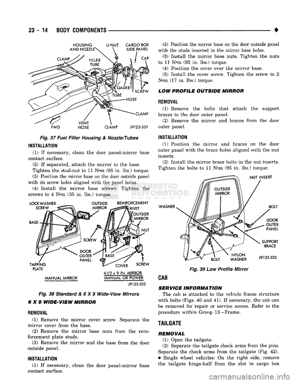
Fig.
37
Fuel
Filler
Housing
& Nozzle/Tubes
INSTALLATION
(1) If necessary, clean the door panel-mirror base
contact surface.
(2) If separated, attach the mirror to the base.
Tighten the stud-nut to 11 N-m (95 in. lbs.) torque. (3) Position the mirror base on the door outside panel
with its screw holes aligned with the panel holes.
(4) Install the mirror base screws. Tighten the
screws to 4 N-m (35 in. lbs.) torque.
LOCKWASHER OUTSIDE REINFORCEMENT
PLATE
61/2 x 9 IN.
MIRROR
MANUAL MIRROR MANUAL
OR
POWER
J9123-332
Fig.
38 Standard&6X9 Wide-View Mirrors
6X9
WIDE-VIEW
MIRROR
REMOVAL
(1) Remove the mirror cover screw. Separate the
mirror cover from the base.
(2) Remove the mirror base nuts from the rein
forcement plate studs.
(3) Remove the mirror and the base from the door
outside panel. (2) Position the mirror base on the door outside panel
with the studs inserted in the mirror base holes.
(3) Install the mirror base nuts. Tighten the nuts
to 11 N-m (95 in. lbs.) torque.
(4) Position the cover over the mirror base. (5) Install the cover screw. Tighten the screw to 2
N-m (17 in. lbs.) torque.
LOW PROFILE OUTSIDE MIRROR
REMOVAL
(1) Remove the bolts that attach the support
braces to the door outer panel. (2) Remove the mirror and braces from the door
outer panel.
INSTALLATION
(1) Position the mirror and braces on the door
outer panel with the brace holes aligned with the nut
inserts.
(2) Install the mirror brace bolts in the nut inserts.
Tighten the bolts to 11 N-m (95 in. lbs.) torque.
WASHER
Fig.
39 Low
Profile
Mirror
CAB
SERVICE
INFORMATION
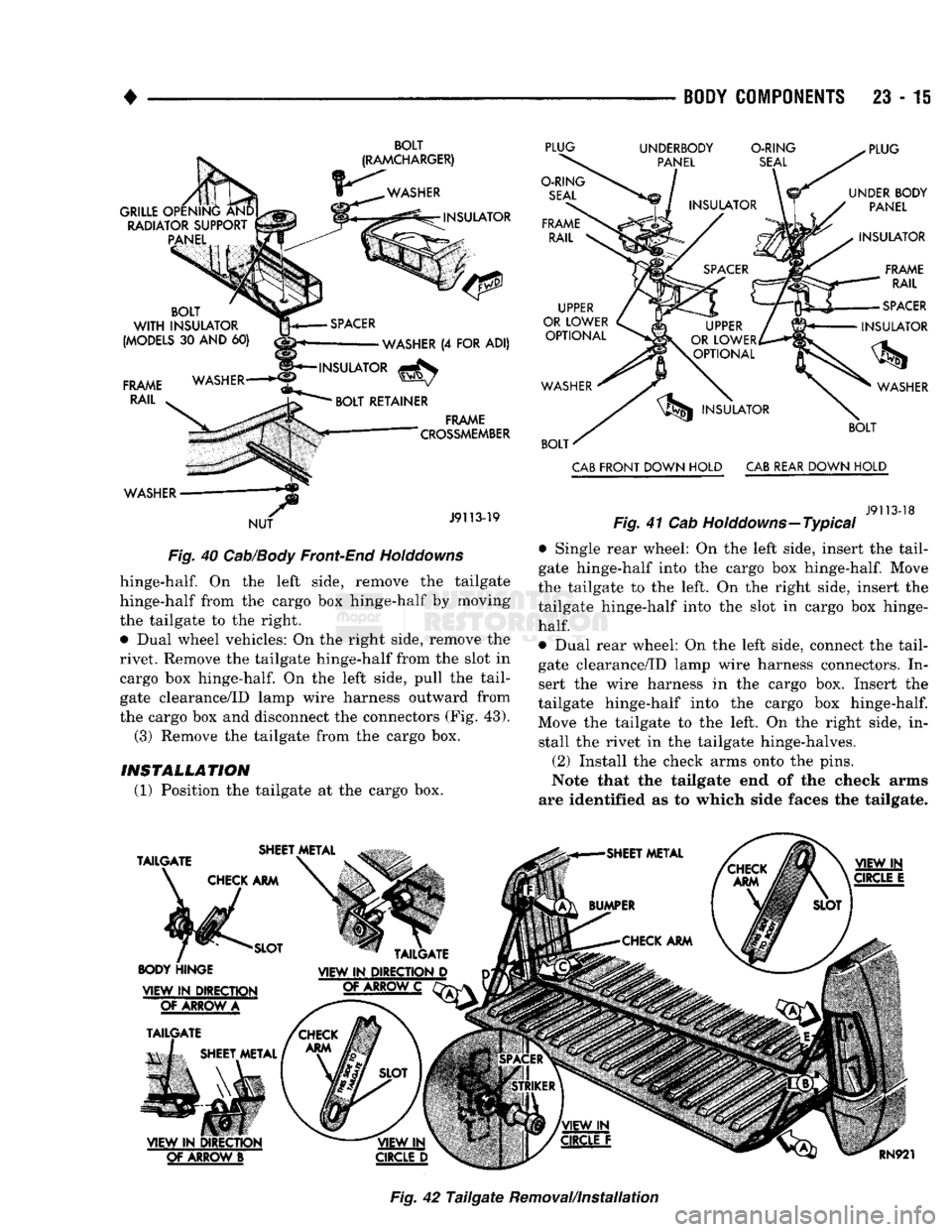
The cab is attached to the vehicle frame structure
with bolts (Figs. 40 and 41). If necessary, the cab can
be removed for repair or service access. Refer to the
procedure within Group 13—Frame.
TAILGATE REMOVAL
(1) Open the tailgate.
(2) Separate the tailgate check arms from the pins.
Separate the check arms from the tailgate (Fig. 42).
• Single wheel vehicles: On the right side, remove
the tailgate hinge-half from the slot in cargo box
INSTALLATION
(1) If necessary, clean the door panel-mirror base
contact surface.
Page 1398 of 1502

•
BODY
COMPONENTS
23 - 15
BOLT
Fig.
40 Cab/Body Front-End Holddowns hinge-half. On the left side, remove the tailgate
hinge-half from the cargo box hinge-half by moving
the tailgate to the right.
• Dual wheel vehicles: On the right side, remove the
rivet. Remove the tailgate hinge-half from the slot in cargo box hinge-half. On the left side, pull the tail
gate clearance/ID lamp wire harness outward from
the cargo box and disconnect the connectors (Fig. 43). (3) Remove the tailgate from the cargo box.
INSTALLATION
(1) Position the tailgate at the cargo box. CAB FRONT DOWN HOLD CAB REAR DOWN HOLD
J9113-18
Fig.
41 Cab Holddowns—Typical
• Single rear wheel: On the left side, insert the tail
gate hinge-half into the cargo box hinge-half. Move
the tailgate to the left. On the right side, insert the
tailgate hinge-half into the slot in cargo box hinge-
half.
• Dual rear wheel: On the left side, connect the tail
gate clearance/ID lamp wire harness connectors. In
sert the wire harness in the cargo box. Insert the
tailgate hinge-half into the cargo box hinge-half.
Move the tailgate to the left. On the right side, in stall the rivet in the tailgate hinge-halves.
(2) Install the check arms onto the pins.
Note that the tailgate end of the check arms
are identified as to which side faces the tailgate.
Fig.
42
Tailgate
Removal/Installation
Page 1399 of 1502

23 - 16
BODY COMPONENTS
(3) Test the handle and latches for correct opera
tion. If necessary, adjust the strikers to eliminate
tailgate looseness and noise.
(4) Close the tailgate.
CONNECTOR
TO
LT
TAIL.
STOP,
TURN
& B/UP
LAMPS
HOUSING
CLEARANCE
AND
ID
LAMPS
J9123-570
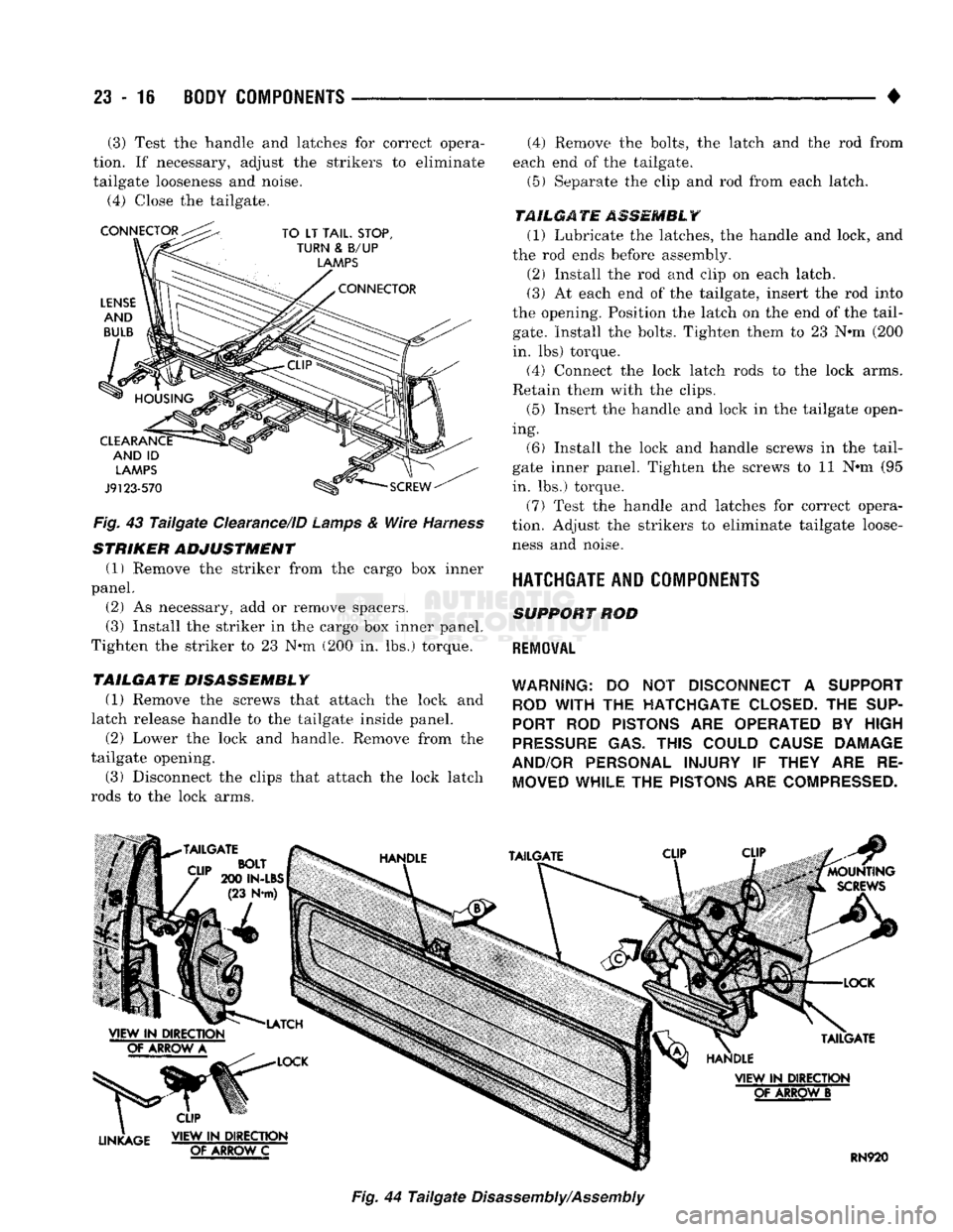
Fig.
43
Tailgate
Clearance/ID
Lamps
&
Wire
Harness
STRIKER
ADJUSTMENT
(1) Remove the striker from the cargo box inner
panel.
(2) As necessary, add or remove spacers. (3) Install the striker in the cargo box inner panel.
Tighten the striker to 23 N-m (200 in. lbs.) torque.
TAILGATE DISASSEMBLY
(1)
Remove the screws that attach the lock and
latch release handle to the tailgate inside panel.
(2) Lower the lock and handle. Remove from the
tailgate opening.
(3) Disconnect the clips that attach the lock latch
rods to the lock arms. (4) Remove the bolts, the latch and the rod from
each end of the tailgate.
(5) Separate the clip and rod from each latch.
TAILGATE
ASSEMBLY
(1) Lubricate the latches, the handle and lock, and
the rod ends before assembly. (2) Install the rod and clip on each latch.
(3) At each end of the tailgate, insert the rod into
the opening. Position the latch on the end of the tail
gate.
Install the bolts. Tighten them to 23 N-m (200
in. lbs) torque.
(4) Connect the lock latch rods to the lock arms.
Retain them with the clips.
(5) Insert the handle and lock in the tailgate open
ing.
(6) Install the lock and handle screws in the tail
gate inner panel. Tighten the screws to 11 N-m (95
in. lbs.) torque.
(7) Test the handle and latches for correct opera
tion. Adjust the strikers to eliminate tailgate loose ness and noise.
HATCHGATE AND COMPONENTS
SUPPORT
ROD
REMOVAL
WARNING:
DO NOT
DISCONNECT
A
SUPPORT ROD
WITH
THE
HATCHGATE CLOSED.
THE
SUP
PORT
ROD
PISTONS
ARE
OPERATED
BY
HIGH
PRESSURE
GAS.
THIS COULD CAUSE DAMAGE
AND/OR PERSONAL INJURY
IF
THEY
ARE RE
MOVED WHILE
THE
PISTONS
ARE
COMPRESSED.
Fig.
44
Tailgate
Disassembly/Assembly