1993 DODGE TRUCK steering wheel
[x] Cancel search: steering wheelPage 4 of 1502
GROUP TAB LOCATOR
Introduction
0
Lubrication
and
Maintenance
2
Front Suspension
and
Axle
3
Rear Suspension
and
Axles
5
Brakes
6
Clutch
7
Cooling System
8
Electrical
9
Engines
11
Exhaust System
and
Intake
Manifold
13
Frame
and Bumpers
14
Fuel
System
16
Propeller Shafts
19
Steering
21
Transmission
and
Transfer Case
22
Wheels and Tires
23
Body Components
24
Heating
and Air
Conditioning
25
Emission Control Systems Component and System Index
Service Manual Comment Forms (Rear
of
Manual)
Page 21 of 1502
0 - 2
LUBRICATION
AND
MAINTENANCE
• Commercial service
When a vehicle is continuously subjected to severe
driving conditions, lubricate:
• Body components
• All the driveline coupling joints
• Steering linkage More often than normal driving conditions
DUSTY
AREAS
With this type of severe driving condition, special
care should be given to the:
• Engine air cleaner filter
• PCV filter
• Crankcase ventilation system
• Brake booster control valve air filter. Verify that the filters and the associated compo
nents are clean. Also verify that they are functioning
effectively. This will minimize the amount of abra sive particles that enter the engine.
OFF-ROAD
(4WD)
OPERATION
After off-road (4WD) operation, inspect the under
side of the vehicle. Inspect the:
• Tires
• Body structure
• Steering components
• Suspension components • Exhaust system
• Threaded fasteners
HARSH
SURFACE ENVIRONMENTS
After extended operation in harsh environments,
the brake drums, brake linings, and rear wheel bear ings should be inspected and cleaned. This will pre
vent wear and erratic brake action.
ROUTINE MAINTENANCE
The following routine maintenance is recommended
on a monthly basis: TIRES—Inspect the tires for unusual wear/damage.
Determine if the inflation pressure is adequate for
the vehicle load. BATTERY—Inspect and clean the terminals.
Tighten the terminals if necessary. FLUIDS—Determine if the component fluid levels
are acceptable. Add fluid, if necessary. LIGHTS/ELECTRICAL—Test all the electrical sys
tems in the vehicle for proper operation. It is also recommended that the engine oil and the
washer fluid level be determined at each fuel fill-up.
VEHICLE
NOISE CONTROL
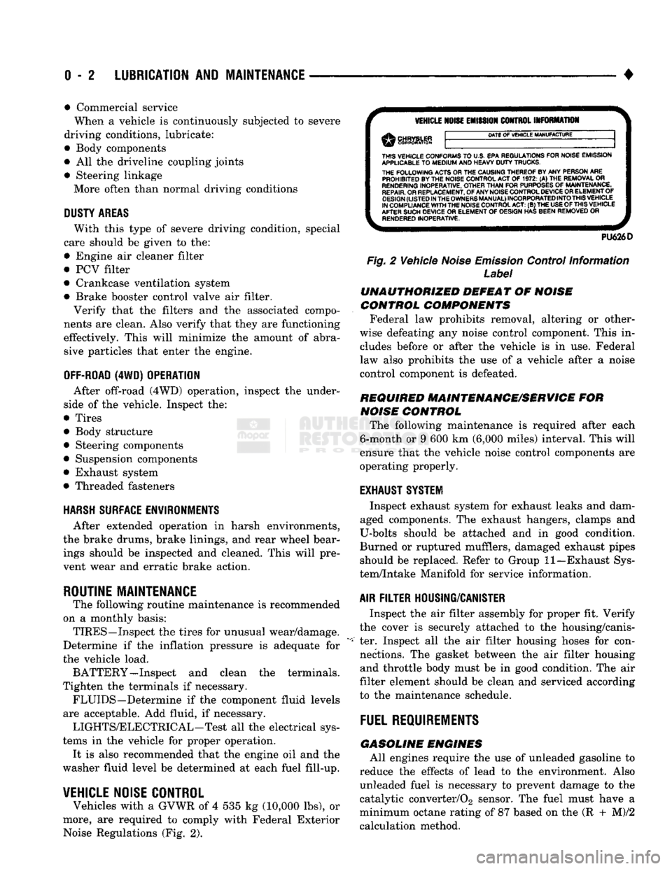
Vehicles with a GVWR of 4 535 kg (10,000 lbs), or
more, are required to comply with Federal Exterior Noise Regulations (Fig. 2).
VEHICLE
NOISE
EMISSION
CONTROL INFORMATION
DATE
OF
VEHICLE
MANUFACTURE
THIS
VEHICLE CONFORMS
TO
U.S. EPA REGULATIONS FOR NOISE EMISSION
APPLICABLE
TO
MEDIUM
AND HEAVY
DUTY
TRUCKS. THE
FOLLOWING
ACTS OR THE CAUSING THEREOF BY ANY PERSON ARE PROHIBITED BY THE NOISE CONTROL ACT
OF 1972. (A) THE
REMOVAL
OR
RENDERING
INOPERATIVE, OTHER
THAN
FOR
PURPOSES
OF
MAINTENANCE,
REPAIR.
OR REPLACEMENT, OF ANY NOISE CONTROL DEVICE OR ELEMENT OF
DESIGN
(LISTED
IN
THE
OWNERS
MANUAL)
INCORPORATED
INTO
THIS
VEHICLE
IN COMPLIANCE
WITH
THE NOISE CONTROL
ACT:
(B) THE
USE
OF
THIS
VEHICLE
AFTER SUCH DEVICE
OR
ELEMENT
OF
DESIGN HAS BEEN REMOVED
OR
RENDERED
INOPERATIVE.
PU626D
Fig.
2 Vehicle
Noise
Emission
Control Information
Label
UNAUTHORIZED
DEFEAT
OF
NOISE
CONTROL COMPONENTS
Federal law prohibits removal, altering or other
wise defeating any noise control component. This in
cludes before or after the vehicle is in use. Federal
law also prohibits the use of a vehicle after a noise
control component is defeated.
REQUIRED MAINTENANCE/SERVICE
FOR
NOISE
CONTROL
The following maintenance is required after each
6-month or 9 600 km (6,000 miles) interval. This will
ensure that the vehicle noise control components are
operating properly.
EXHAUST SYSTEM
Inspect exhaust system for exhaust leaks and dam
aged components. The exhaust hangers, clamps and
U-bolts should be attached and in good condition.
Burned or ruptured mufflers, damaged exhaust pipes should be replaced. Refer to Group 11—Exhaust Sys
tem/Intake Manifold for service information.
AIR
FILTER
HOUSING/CANISTER
Inspect the air filter assembly for proper fit. Verify
the cover is securely attached to the housing/canis
ter. Inspect all the air filter housing hoses for con nections. The gasket between the air filter housing and throttle body must be in good condition. The air
filter element should be clean and serviced according
to the maintenance schedule.
FUEL
REQUIREMENTS
GASOLINE
ENGINES
All engines require the use of unleaded gasoline to
reduce the effects of lead to the environment. Also unleaded fuel is necessary to prevent damage to the
catalytic converter/02 sensor. The fuel must have a
minimum octane rating of 87 based on the (R + M)/2
calculation method.
Page 30 of 1502

LUBRICATION
AND
MAINTENANCE
0-11
J
DRIVE-ON
HOIST
I
FRAME
CONTACT
HOIST
TWIN
POST
CHASSIS
HOIST
FLOOR
JACK
RROOD30
Fig.
8 Correct Vehicle Lifting
Locations
An axle tube
A body side sill
A steering linkage component
A drive shaft
The engine or transmission oil pan
The fuel tank
• A front suspension arm Use the correct frame rail lifting locations only
(Fig. 8).
HOIST A vehicle can be lifted with:
• A single-post, frame-contact hoist
• A twin-post, chassis hoist
• A ramp-type, drive-on hoist
When a frame-contact type hoist is used, verify
that the lifting pads are positioned properly (Fig. 8).
WARNING:
WHEN
A
SERVICE
PROCEDURE
RE
QUIRES
THE
REMOVAL
OF
THE
REAR
AXLE,
FUEL
TANK,
OR
SPARE
TIRE,
EITHER:
• PLACE ADDITIONAL WEIGHT ON THE REAR
END OF THE VEHICLE
« ATTACH THE VEHICLE TO THE HOIST
« PLACE JACK STANDS UNDER THE VEHICLE
FOR SUPPORT TO PREVENT TIPPING WHEN
THE CENTER OF BALANCE CHANGES
4WD VEHICLES A standard hoist can be used to lift a 4WD vehicle.
The hoist should be inspected for adequate clearance. The lift arms, pads or ramps should be adjusted to
ensure that there is adequate clearance (Fig. 9).
ADJUSTMENT
PAD
ii 7
MAINTAIN
CLEARANCE
HOIST
ARM
RK44
Fig.
9 Lifting 4WD Vehicle
With
Single-Post
Hoist—
Typical
When a twin-post hoist is used, a 4 x 4 x 12-inch
wood spacer also could be required. Place the wood spacer under the front axle (opposite the differential
housing). This will maintain balance and level lift ing.
CAUTION:
The
block
that
is
used must
be
secured in
a
safe manner. This
will
ensure
that
it
will
not un
balance
the
vehicle.
VEHICLE
TOWING
RECOMMENDATIONS
When it is necessary to tow a Ram Truck, the rec
ommended method is either:
• the sling-type, rear-end raised towing method; or
• the wheel-lift towing method with a tow dolly lo
cated under the front wheels. A vehicle with flat-bed hauling equipment can also
be used to transport a disabled vehicle.
SLING-TYPE
FLAT
BED
RR0OD29
Fig.
10 Tow Vehicles
With
Approved
Equipment
Page 31 of 1502

0 - 12
LUBRICATION
AND
MAINTENANCE
• A vehicle equipped with SAE approved sling-type
towing equipment can be used (Fig. 10). However,
many vehicles are equipped with air dams, spoilers, and/or ground effect panels. In this case a wheel-lift
towing vehicle or a flat-bed hauling vehicle is recom mended (Fig. 10). If a flat bed device is used, the ap
proach angle should not exceed 15 degrees.
GROUND CLEARANCE The lifted wheels of the disabled vehicle should be
a minimum of 10 cm (4 in.) off the ground. Make
sure there is enough clearance at the opposite end.
This is critical when towing over rough terrain. If necessary, the rear ground clearance can be increased by removing the wheels from the lifted end
and then towing with the lifted end closer to the
ground. If the rear wheels are removed, secure the
brake drums. A 20 cm (8 in.) ground clearance must
be maintained between brake drums or rotors and the ground.
SAFETY PRECAUTIONS The following safety precautions must be consid
ered when preparing for and during a vehicle towing operation:
• Remove exhaust pipe tips that interfere with the
tow sling and crossbar • Padding should be placed between the tow sling/
crossbar and any painted surfaces
• If the vehicle is damaged, secure the loose and pro
truding parts
• Always use a safety chain system that is indepen dent of the lifting and towing equipment
• When placing tow hooks on the rear axle, position them so they do not damage the brake tubing or
hoses
• Do not allow any of the towing equipment to con
tact the fuel tank
• Do not tow the vehicle by connecting to the front
or rear shock absorbers
• The operator should not go under a vehicle while
it is lifted by the towing equipment. The vehicle
should first be supported by safety stands
• Do not allow passengers in a vehicle being towed
• Observe all state and local laws involving warning signals, night illumination, speed, etc.
• Do not exceed a towing speed of 48 km/h (30 mph)
• Avoid towing distances of more than 24 km (15
miles) whenever possible • Do not attach tow chains or a tow sling to a
bumper, the steering linkage, the universal joints, or a drive shaft
REAR-END RAISED TOWING It is recommended that the rear-end raised towing
method be used. Vehicles can be towed with the front
wheels on the ground for extended distances at speeds not exceeding 48 km/h (30 mph) (Fig. 11). (1) Attach the J-hooks around the axle shaft tubes
outboard of the rear springs. (2) Position and center the sling under and for
ward of the rear bumper. (3) Attach safety chains (with pads) at each end of
the rear bumper.
(4) Turn the ignition switch to the OFF position to
unlock the steering wheel. (5) Clamp the steering wheel with the front wheels
in the straight ahead position.
CAUTION:
Do not use the steering
column
lock
to
secure
front
wheel
in the straight-ahead
position.
(6) Shift the transmission to NEUTRAL.
POSITION CENTER BAR FORWARD
OF
BUMPER
-
/
J-HOOKS OUTBOARD
OF
SPRINGS
RN967A
Fig. 11 Rear-End
Raised
Towing
FRONT'END RAISED TOWING If a vehicle cannot be towed from the rear, the
front-end raised towing method normally can be
used (Fig. 12). (1) Center the sling with the bumper and position
it at the frame front crossmember.
CAUTION:
Use tow
chains
with
J-hooks
for
con
necting
to the
disabled
vehicle's
lower
suspension
arms.
Never use
T-hooks.
(2) Route the J-hooks and tow chains over the
steering linkage outboard of the coil spring.
(3) Attach the J-hooks to the outer end of the
lower suspension arms.
(4) Raise the vehicle.
(5.) Attach the safety chains to the disabled vehicle
at the frame rails.
Vehicles equipped with a MANUAL TRANSMIS
SION can be towed with the rear wheels on the
Page 47 of 1502
0
- 28
LUBRICATION
AND
MAINTENANCE
•
CHASSIS AND BODY
page
Body
Component Mechanisms
32
Front
Suspension
Ball
Joints
28
Front
Wheel Bearings
29
Headlamps
32
Lower
and
Upper Suspension
Arm
Bushings
.... 30
Manual
Steering Gear
28
STEERING
LINKAGE
INSPECTION When
a
vehicle
is
raised
for
maintenance under
the vehicle,
all
steering components should
be
checked.
LUBRICATION SCHEDULE The steering linkage
is
lubricated with
a
chassis
lubricant. However,
it is
recommended that
the
link
age
be
inspected
and
lubricated after each:
•
24 000 km
(15,000 miles) interval
or
every
6
months,
for 2WD
vehicles subject
to the
LIGHT
DUTY CYCLE Maintenance Schedule
•
9 600 km
(6,000 miles) interval
or
every
6
months,
for
2WD
vehicles subject
to the
HEAVY DUTY
CY
CLE Maintenance Schedule
•
12 000 km
(7,500 miles) interval
or
every
6
months,
for 4WD
vehicles subject
to the
LIGHT DUTY CYCLE Maintenance Schedule
•
9 600 km
(6,000 miles) interval
or
every
6
months,
for
4WD
vehicles subject
to the
HEAVY DUTY
CY
CLE Maintenance Schedule.
LUBRICATION (1) Inspect
the
steering linkage
for
looseness
and
excessive wear. (2) Replace,
all
ruptured seals
and
damaged steer
ing linkage components. Damaged seals should
be re
placed
to
prevent leakage
and
contamination
of the
lubricant.
CAUTION:
Use
care
to
prevent lubricant from
con
tacting
the
brake rotors.
(3) Lubricate
the
steering linkage:
• Clean
the
Zerk type lubrication fittings
on the tie-
rod
and
center link ball-stud ends
• Lubricate
the
ball studs with MOPAR®Multi-Mile- age Lubricant
• Wipe
the
excess lubricant from
the
exterior sur
faces
of the
ball joints
page
Power
Brake System
30
Power
Steering System
. . 29
Rear
Wheel Bearings
30
Speedometer Cable
33
Steering Linkage
28
Tires
32
FRONT
SUSPENSION
BALL JOINTS
INSPECTION When
a
vehicle
is
raised
for
lubrication/general
maintenance,
the
ball joints should
be
inspected.
LUBRICATION SCHEDULE The front suspension ball joints
are
lubricated dur
ing manufacture with
a
long-life chassis lubricant.
However,
it is
recommended that
the
ball joints
be
inspected
and the
studs lubricated:
•
At
each
36 000 km
(22,500 miles) interval
or
every
2 years,
for
vehicles subject
to the
LIGHT DUTY
CY
CLE Maintenance Schedule
•
At
each
9 600 km
(6,000 miles) interval
or
every
2
years,
for
vehicles subject
to the
HEAVY DUTY
CY
CLE Maintenance Schedule.
4WD vehicles that
are
frequently driven
off-
road should
be
lubricated
at
every engine
oil
change.
LUBRICATION (1) Inspect
the
front suspension. Examine
the
ball
studs
for
looseness
and
excessive wear. (2) Replace
all
torn ball-stud seals
and
damaged
ball joints. Damaged seals should
be
replaced
to
pre vent leakage
and
contamination.
CAUTION:
Use
care
to
prevent lubricant from
con
tacting
the
brake rotors.
(3) Lubricate
the
ball studs:
• Clean
the
Zerk type lubrication fittings
on the
ball-stud ends
• Lubricate
the
ball studs with MOPAR®Multi-Mile-age Lubricant
• Wipe
the
excess lubricant from
the
exterior sur
faces
of the
ball joints
MANUAL
STEERING
GEAR
LUBRICATION Manual steering gears
are
permanently lubricated
during manufacture. Periodic lubrication
is not
nec
essary.
Page 48 of 1502
•
LUBRICATION
AND
MAINTENANCE
0 - 29
POWER STEERING SYSTEM
SERVICE SCHEDULE
FLUID
LEWEL
WARNING.
THE
POWER
STEERING
FLUID LEVEL
SHOULD
ALWAYS
BE
CHECKED
WITH THE EN
GINE
OFF TO
PREVENT
PERSONAL
INJURY.
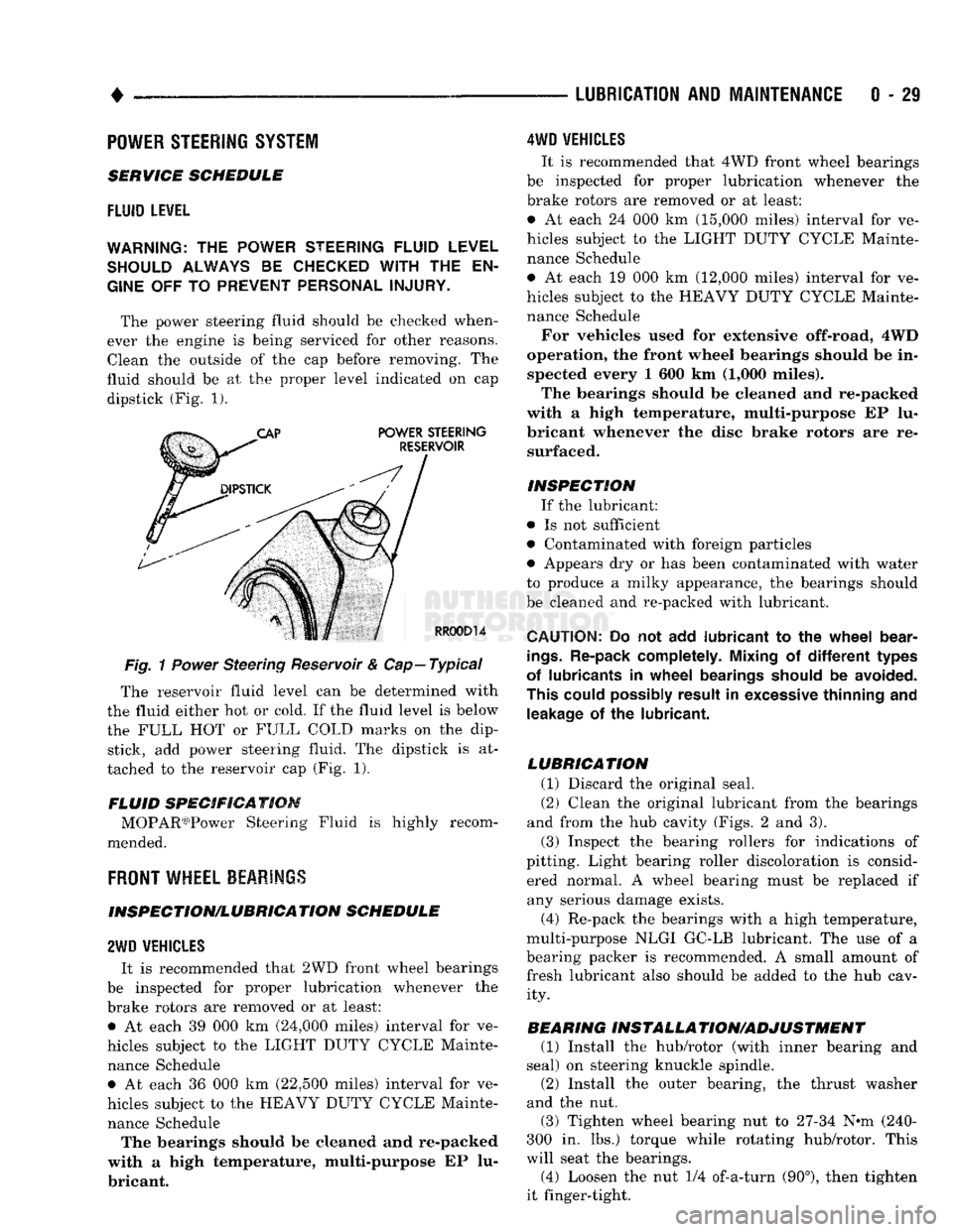
The power steering fluid should be checked when
ever the engine is being serviced for other reasons. Clean the outside of the cap before removing. The
fluid should be at the proper level indicated on cap dipstick (Fig. 1).
Fig.
1
Power
Steering Reservoir & Cap—Typical
The reservoir fluid level can be determined with
the fluid either hot or cold. If the fluid level is below
the FULL HOT or FULL COLD marks on the dip stick, add power steering fluid. The dipstick is at
tached to the reservoir cap (Fig. 1).
FLUID SPECIFICATION MOPAR03)Power Steering Fluid is highly recom
mended.
FRONT
WHEEL BEARINGS
INSPECTION/LUBRICATION SCHEDULE
2WD
VEHICLES
It is recommended that 2WD front wheel bearings
be inspected for proper lubrication whenever the
brake rotors are removed or at least: • At each 39 000 km (24,000 miles) interval for ve
hicles subject to the LIGHT DUTY CYCLE Mainte nance Schedule • At each 36 000 km (22,500 miles) interval for ve
hicles subject to the HEAVY DUTY CYCLE Mainte nance Schedule The bearings should be cleaned and re-packed
with a high temperature, multi-purpose EP lu
bricant.
4WD
VEHICLES
It is recommended that 4WD front wheel bearings
be inspected for proper lubrication whenever the
brake rotors are removed or at least:
• At each 24 000 km (15,000 miles) interval for ve
hicles subject to the LIGHT DUTY CYCLE Mainte nance Schedule
• At each 19 000 km (12,000 miles) interval for ve
hicles subject to the HEAVY DUTY CYCLE Mainte nance Schedule
For vehicles used for extensive off-road, 4WD
operation, the front wheel bearings should be in spected every 1 600 km (1,000 miles).
The bearings should be cleaned and re-packed
with a high temperature, multi-purpose EP lu
bricant whenever the disc brake rotors are re surfaced.
INSPECTION If the lubricant:
• Is not sufficient
• Contaminated with foreign particles
• Appears dry or has been contaminated with water
to produce a milky appearance, the bearings should
be cleaned and re-packed with lubricant.
CAUTION:
Do not add
lubricant
to the
wheel
bear
ings.
Re-pack completely. Mixing
of
different
types
of lubricants
in
wheel
bearings should
be
avoided.
This could possibly result
in
excessive thinning
and
leakage
of the
lubricant.
LUBRICATION (1) Discard the original seal.
(2) Clean the original lubricant from the bearings
and from the hub cavity (Figs. 2 and 3).
(3) Inspect the bearing rollers for indications of
pitting. Light bearing roller discoloration is consid ered normal. A wheel bearing must be replaced if any serious damage exists.
(4) Re-pack the bearings with a high temperature,
multi-purpose NLGI GC-LB lubricant. The use of a
bearing packer is recommended. A small amount of fresh lubricant also should be added to the hub cav ity.
BEARING INSTALLA TION/ADJUSTMENT (1) Install the hub/rotor (with inner bearing and
seal) on steering knuckle spindle.
(2) Install the outer bearing, the thrust washer
and the nut.
(3) Tighten wheel bearing nut to 27-34 N^m (240-
300 in. lbs.) torque while rotating hub/rotor. This
will seat the bearings.
(4) Loosen the nut 1/4 of-a-turn (90°), then tighten
it finger-tight.
Page 54 of 1502
•
FRONT SUSPENSION
AND
AXLE
2 - 1
CONTENTS
page
FRONT SUSPENSION—2WD VEHICLES
......
7
FRONT SUSPENSION—4WD VEHICLES
14
FRONT WHEEL
ALIGNMENT
...............
3
GENERAL INFORMATION
1
page
MODEL
44
FRONT AXLE
17
MODEL
80
FRONT AXLE
49
TORQUE SPECIFICATIONS
75
GENERAL
INFORMATION
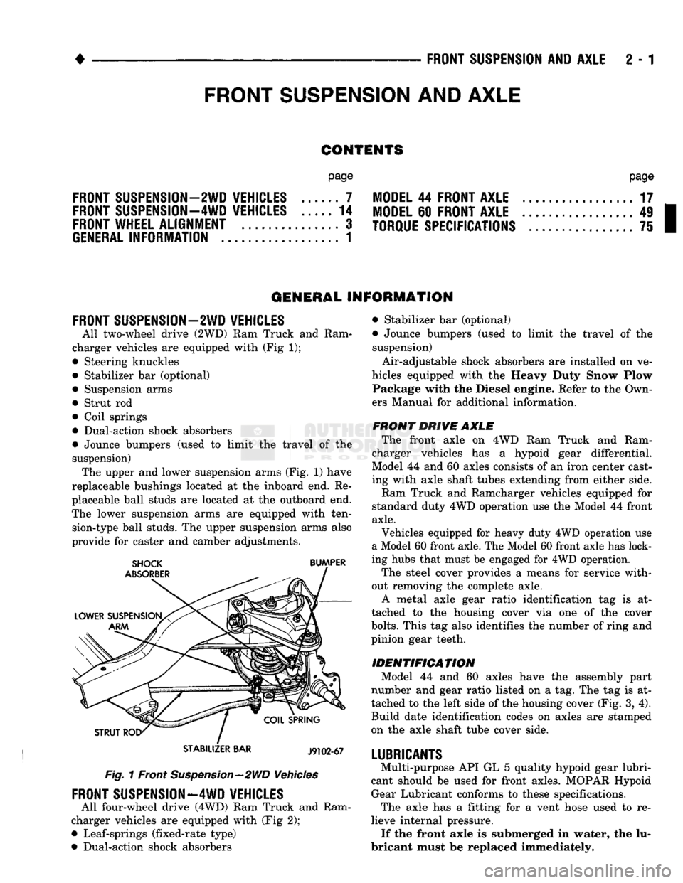
FRONT SUSPENSION—2WD VEHICLES
All two-wheel drive (2WD)
Ram
Truck
and
Ram
charger vehicles
are
equipped with (Fig
1);
• Steering knuckles
• Stabilizer
bar
(optional) • Suspension arms
• Strut
rod
• Coil springs
• Dual-action shock absorbers
• Jounce bumpers (used
to
limit
the
travel
of the
suspension) The upper and lower suspension arms (Fig.
1)
have
replaceable bushings located
at the
inboard end.
Re
placeable ball studs
are
located
at
the
outboard end.
The lower suspension arms
are
equipped with ten sion-type ball studs. The upper suspension arms also
provide
for
caster
and
camber adjustments.
STABILIZER
BAR
J9102-67
Fig. 1 Front Suspension—2WD Vehicles
FRONT SUSPENSION—4WD VEHICLES
All four-wheel drive (4WD) Ram Truck
and
Ram
charger vehicles
are
equipped with (Fig
2);
• Leaf-springs (fixed-rate type)
• Dual-action shock absorbers • Stabilizer
bar
(optional)
• Jounce bumpers (used
to
limit
the
travel
of the
suspension)
Air-adjustable shock absorbers
are
installed
on
ve
hicles equipped with
the
Heavy Duty Snow Plow Package with
the
Diesel engine. Refer
to
the Own
ers Manual
for
additional information.
FRONT DRIVE AXLE The front axle
on 4WD Ram
Truck
and
Ram
charger vehicles
has a
hypoid gear differential.
Model
44
and
60
axles consists
of
an iron center cast
ing with axle shaft tubes extending from either side.
Ram Truck
and
Ramcharger vehicles equipped
for
standard duty 4WD operation use
the
Model
44
front
axle.
Vehicles equipped
for
heavy duty 4WD operation
use
a Model 60 front axle. The Model 60 front axle has lock
ing hubs that must
be
engaged
for
4WD operation.
The steel cover provides
a
means
for
service with
out removing
the
complete axle. A metal axle gear ratio identification
tag is at
tached
to the
housing cover
via one of the
cover
bolts.
This
tag
also identifies
the
number
of
ring and
pinion gear teeth.
IDENTIFICATION Model
44 and 60
axles have
the
assembly part
number
and
gear ratio listed
on a
tag. The
tag
is at
tached
to
the
left side
of
the housing cover (Fig.
3,
4).
Build date identification codes
on
axles
are
stamped
on
the
axle shaft tube cover side.
LUBRICANTS
Multi-purpose API
GL
5
quality hypoid gear lubri
cant should
be
used
for
front axles. MOPAR Hypoid Gear Lubricant conforms
to
these specifications. The axle
has a
fitting
for a
vent hose used
to re
lieve internal pressure. If the front axle
is
submerged
in
water,
the
lu
bricant must
be
replaced immediately.
FRONT
SUSPENSION
AND
AXLE
Page 56 of 1502
FRONT SUSPENSION
AND
AXLE
2 - 3
FRONT
WHEEL
ALIGNMENT
GENERAL
INFORMATION
Front wheel alignment involves
the
correct posi
tioning
of the
tire contact patch
in
relation
to the
pavement.
The
positioning
is
accomplished through
the suspension
and
steering linkage adjustments.
An
alignment
is
essential
for
efficient steering
and
direc
tional stability.
The
most important factors
of
front
end alignment
are
camber, caster
and toe
position. Routine inspection
of
the front
suspension
and
steering components
is a
good
preventative
maintenance practice.
Inspection
also
helps
to
ensure
safe operation
of the
vehicle.
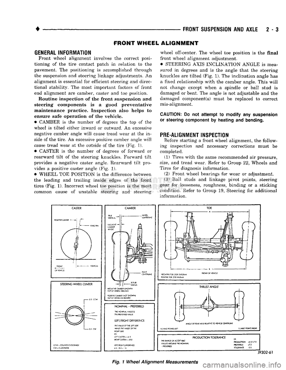
• CAMBER
is the
number
of
degrees
the top of the
wheel
is
tilted either inward
or
outward.
An
excessive
negative camber angle will cause tread wear
at the in
side
of
the tire.
An
excessive positive camber angle will
cause tread wear
at the
outside
of
the tire (Fig.
1),
• CASTER
is the
number
of
degrees
of
forward
or
rearward tilt
of the
steering knuckles. Forward tilt
provides
a
negative caster angle. Rearward tilt pro vides
a
positive caster angle
(Fig. 1).
• WHEEL
TOE
POSITION
is the
difference between
the leading
and
trailing inside edges
of the
front
tires (Fig.
1).
Incorrect wheel
toe
position
is the
most common cause
of
unstable steering
and
steering wheel off-center.
The
wheel
toe
position
is the
final
front wheel alignment adjustment. • STEERING AXIS INCLINATION ANGLE
is
mea
sured
in
degrees
and is the
angle that
the
steering
knuckles
are
tilted (Fig. 1).
The
inclination angle
has
a fixed relationship with
the
camber angle. This will
not change except when
a
spindle
or
ball stud
is
damaged
or
bent.
The
angle
is not
adjustable
and the
damaged component(s) must
be
replaced
to
correct
mis-alignment.
CAUTION:
Do not
attempt to modify
any
suspension
or steering
component
by
heating
and
bending.
PRE-ALIGNMENT INSPECTION
Before starting
a
front wheel alignment,
the
follow
ing inspection
and
necessary corrections must
be
completed.
(1)
Tires with
the
same recommended
air
pressure,
size,
and
tread wear. Refer
to
Group
22,
Wheels
and
Tires
for
diagnosis information. (2) Front wheel bearings
for
wear
or
adjustment.
(3) Ball studs
and
linkage pivot points, steering
gear
for
looseness, roughness, binding
or a
sticking
condition. Refer
to
Group
19,
Steering
for
additional information.
CASTER
POSITIVE CASTER
STEERING
WHEEL CENTER
i 0.5
CCW
0
5
CW
CCW
=
COUNTER CLOCKWISE
CW
-
CLOCKWISE
CAMBER
NEGATIVE CAMBER (SHOWN)
TOP
OF
WHEEL INBOARD
POSITIVE CAMBER
(NOT
SHOWN)
TOP
OF
WHEEL OUTBOARD
NOMINAL-PREFERRED
THE NOMINAL VALUE
IS
THE
PREFERRED
VALUE
LEFT/RIGHT
DIFFERENCE
THE VALUE
Of
THE LEFT SIDE
MINUS THE VALUE
OF
THE
RIGHT SIDE
EX.
If
FT CASTER
- +6 5
RIGHT
CASTER
»
+8.0
LEFT/RIGHT DIFFERENCE
65 8.0
=
1
5
TOE
NEGATIVE TOE (TOE
OUT)
B>A
POSITIVE TOE (TOE
IN) 6
FRONT
Of
VEHICLE
ft
THRUST
ANGLE
ANGLE
OF
REAR
AXLE RELATIVE
TO
VEHICLE CENTERUNE
(+)
AXLE POINTS LEFT
(-)
AXLE POINTS RIGHT
PRODUCTION
TOLERANCE
THE RANGE
Of
ACCEPTABLE
VALUES
AROUND THE NOMINAL
-
PREFERRED PRODUCTION
+6.5A7.5
PREFERRED:
+7.0
TOLERANCE:
0.5
J9302-61
Fig.
1
Wheel
Alignment
Measurements