1993 DODGE TRUCK washer fluid
[x] Cancel search: washer fluidPage 21 of 1502
0 - 2
LUBRICATION
AND
MAINTENANCE
• Commercial service
When a vehicle is continuously subjected to severe
driving conditions, lubricate:
• Body components
• All the driveline coupling joints
• Steering linkage More often than normal driving conditions
DUSTY
AREAS
With this type of severe driving condition, special
care should be given to the:
• Engine air cleaner filter
• PCV filter
• Crankcase ventilation system
• Brake booster control valve air filter. Verify that the filters and the associated compo
nents are clean. Also verify that they are functioning
effectively. This will minimize the amount of abra sive particles that enter the engine.
OFF-ROAD
(4WD)
OPERATION
After off-road (4WD) operation, inspect the under
side of the vehicle. Inspect the:
• Tires
• Body structure
• Steering components
• Suspension components • Exhaust system
• Threaded fasteners
HARSH
SURFACE ENVIRONMENTS
After extended operation in harsh environments,
the brake drums, brake linings, and rear wheel bear ings should be inspected and cleaned. This will pre
vent wear and erratic brake action.
ROUTINE MAINTENANCE
The following routine maintenance is recommended
on a monthly basis: TIRES—Inspect the tires for unusual wear/damage.
Determine if the inflation pressure is adequate for
the vehicle load. BATTERY—Inspect and clean the terminals.
Tighten the terminals if necessary. FLUIDS—Determine if the component fluid levels
are acceptable. Add fluid, if necessary. LIGHTS/ELECTRICAL—Test all the electrical sys
tems in the vehicle for proper operation. It is also recommended that the engine oil and the
washer fluid level be determined at each fuel fill-up.
VEHICLE
NOISE CONTROL
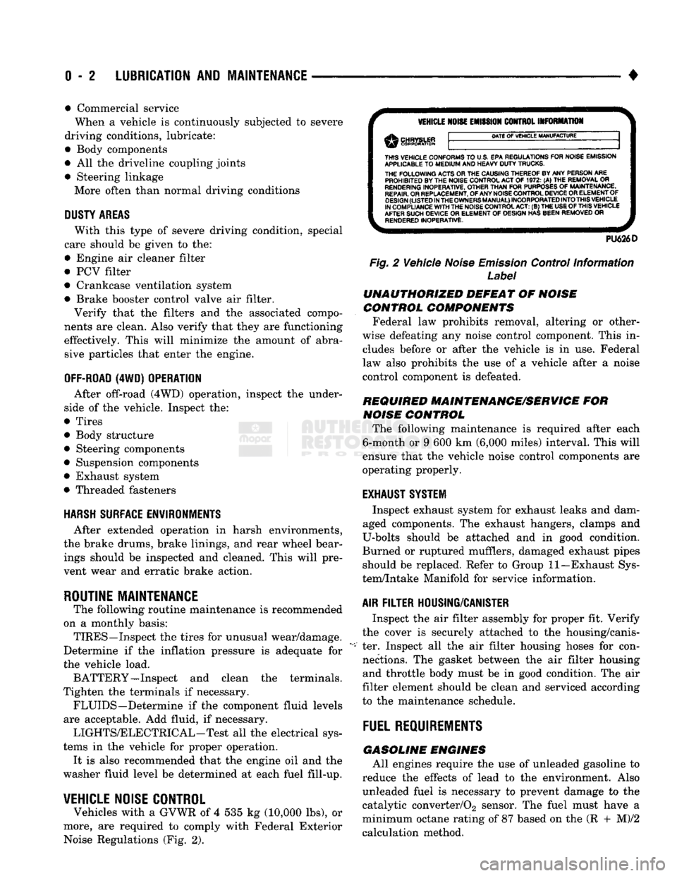
Vehicles with a GVWR of 4 535 kg (10,000 lbs), or
more, are required to comply with Federal Exterior Noise Regulations (Fig. 2).
VEHICLE
NOISE
EMISSION
CONTROL INFORMATION
DATE
OF
VEHICLE
MANUFACTURE
THIS
VEHICLE CONFORMS
TO
U.S. EPA REGULATIONS FOR NOISE EMISSION
APPLICABLE
TO
MEDIUM
AND HEAVY
DUTY
TRUCKS. THE
FOLLOWING
ACTS OR THE CAUSING THEREOF BY ANY PERSON ARE PROHIBITED BY THE NOISE CONTROL ACT
OF 1972. (A) THE
REMOVAL
OR
RENDERING
INOPERATIVE, OTHER
THAN
FOR
PURPOSES
OF
MAINTENANCE,
REPAIR.
OR REPLACEMENT, OF ANY NOISE CONTROL DEVICE OR ELEMENT OF
DESIGN
(LISTED
IN
THE
OWNERS
MANUAL)
INCORPORATED
INTO
THIS
VEHICLE
IN COMPLIANCE
WITH
THE NOISE CONTROL
ACT:
(B) THE
USE
OF
THIS
VEHICLE
AFTER SUCH DEVICE
OR
ELEMENT
OF
DESIGN HAS BEEN REMOVED
OR
RENDERED
INOPERATIVE.
PU626D
Fig.
2 Vehicle
Noise
Emission
Control Information
Label
UNAUTHORIZED
DEFEAT
OF
NOISE
CONTROL COMPONENTS
Federal law prohibits removal, altering or other
wise defeating any noise control component. This in
cludes before or after the vehicle is in use. Federal
law also prohibits the use of a vehicle after a noise
control component is defeated.
REQUIRED MAINTENANCE/SERVICE
FOR
NOISE
CONTROL
The following maintenance is required after each
6-month or 9 600 km (6,000 miles) interval. This will
ensure that the vehicle noise control components are
operating properly.
EXHAUST SYSTEM
Inspect exhaust system for exhaust leaks and dam
aged components. The exhaust hangers, clamps and
U-bolts should be attached and in good condition.
Burned or ruptured mufflers, damaged exhaust pipes should be replaced. Refer to Group 11—Exhaust Sys
tem/Intake Manifold for service information.
AIR
FILTER
HOUSING/CANISTER
Inspect the air filter assembly for proper fit. Verify
the cover is securely attached to the housing/canis
ter. Inspect all the air filter housing hoses for con nections. The gasket between the air filter housing and throttle body must be in good condition. The air
filter element should be clean and serviced according
to the maintenance schedule.
FUEL
REQUIREMENTS
GASOLINE
ENGINES
All engines require the use of unleaded gasoline to
reduce the effects of lead to the environment. Also unleaded fuel is necessary to prevent damage to the
catalytic converter/02 sensor. The fuel must have a
minimum octane rating of 87 based on the (R + M)/2
calculation method.
Page 41 of 1502
0
- 22
LUBRICATION
AND
MAINTENANCE
DRIVETRAIN
INDEX
page
Axles
25
Clutch
and
Brake Pedal
Bushings
............ 22
Clutch Master Cylinder
22
Drive Shafts
26
page
Front Axle U-Joint
and
Pivot Bearings
......... 26
Transfer
Case
(4WD
Vehicles)
. . ........ 24
Transmissions
. 22
CLUTCH
AND
BRAKE PEDAL
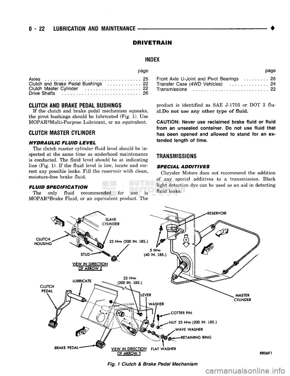
If the clutch and brake pedal mechanism squeaks,
the pivot bushings should be lubricated (Fig. 1). Use
MOPAR®Multi-Purpose Lubricant, or an equivalent.
CLUTCH
MASTER CYLINDER
HYDRAULIC FLUID LEVEL The clutch master cylinder fluid level should be in
spected at the same time as underhood maintenance
is conducted. The fluid level should be at indicating
line (Fig. 1). If the fluid level is low, locate and cor
rect any possible leaks. Fill the reservoir with clean,
moisture-free brake fluid.
FLUID SPECIFICATION The only fluid recommended for use is
MOPAR®Brake Fluid, or an equivalent product. The
SLAVE
CYLINDER
CLUTCH
HOUSING
23
N«m
(200 IN.
LBS.)
product is identified as SAE J-1703 or DOT 3 flu
id.Do not use any other type of
fluid.
CAUTION:
Never
use
reclaimed brake fluid
or
fluid
from
an
unsealed container.
Do not use
fluid that
has
been opened
and
allowed
to
stand
for an ex
tended length
of
time.
TRANSMISSIONS
SPECIAL ADDITIVES Chrysler Motors does not recommend the addition
of any special additives to a transmission. Black
light detection dye can be used as an aid in detecting
fluid leaks.
RESERVOIR
STUD
VIEW
IN
DIRECTION
GtAKBQWZ
LUBRICATE
CLUTCH
PEDAL
23 N#m
(200 IN. LBS.)
5
N«m
(40 IN.
LBS
MASTER
CYLINDER
COTTER
PIN
NUT
23 N*m (200 IN.
LBS.) WAVE WASHER RETAINING RING
BRAKE
PEDAL VIEW
IN
DIRECTION FLAT WASHER
OF ARROW
Y
RR06F1
Fig.
1
Clutch
& Brake
Pedal
Mechanism
Page 48 of 1502
•
LUBRICATION
AND
MAINTENANCE
0 - 29
POWER STEERING SYSTEM
SERVICE SCHEDULE
FLUID
LEWEL
WARNING.
THE
POWER
STEERING
FLUID LEVEL
SHOULD
ALWAYS
BE
CHECKED
WITH THE EN
GINE
OFF TO
PREVENT
PERSONAL
INJURY.
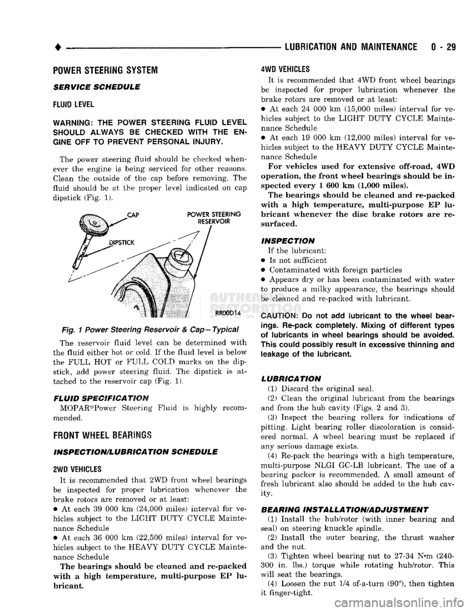
The power steering fluid should be checked when
ever the engine is being serviced for other reasons. Clean the outside of the cap before removing. The
fluid should be at the proper level indicated on cap dipstick (Fig. 1).
Fig.
1
Power
Steering Reservoir & Cap—Typical
The reservoir fluid level can be determined with
the fluid either hot or cold. If the fluid level is below
the FULL HOT or FULL COLD marks on the dip stick, add power steering fluid. The dipstick is at
tached to the reservoir cap (Fig. 1).
FLUID SPECIFICATION MOPAR03)Power Steering Fluid is highly recom
mended.
FRONT
WHEEL BEARINGS
INSPECTION/LUBRICATION SCHEDULE
2WD
VEHICLES
It is recommended that 2WD front wheel bearings
be inspected for proper lubrication whenever the
brake rotors are removed or at least: • At each 39 000 km (24,000 miles) interval for ve
hicles subject to the LIGHT DUTY CYCLE Mainte nance Schedule • At each 36 000 km (22,500 miles) interval for ve
hicles subject to the HEAVY DUTY CYCLE Mainte nance Schedule The bearings should be cleaned and re-packed
with a high temperature, multi-purpose EP lu
bricant.
4WD
VEHICLES
It is recommended that 4WD front wheel bearings
be inspected for proper lubrication whenever the
brake rotors are removed or at least:
• At each 24 000 km (15,000 miles) interval for ve
hicles subject to the LIGHT DUTY CYCLE Mainte nance Schedule
• At each 19 000 km (12,000 miles) interval for ve
hicles subject to the HEAVY DUTY CYCLE Mainte nance Schedule
For vehicles used for extensive off-road, 4WD
operation, the front wheel bearings should be in spected every 1 600 km (1,000 miles).
The bearings should be cleaned and re-packed
with a high temperature, multi-purpose EP lu
bricant whenever the disc brake rotors are re surfaced.
INSPECTION If the lubricant:
• Is not sufficient
• Contaminated with foreign particles
• Appears dry or has been contaminated with water
to produce a milky appearance, the bearings should
be cleaned and re-packed with lubricant.
CAUTION:
Do not add
lubricant
to the
wheel
bear
ings.
Re-pack completely. Mixing
of
different
types
of lubricants
in
wheel
bearings should
be
avoided.
This could possibly result
in
excessive thinning
and
leakage
of the
lubricant.
LUBRICATION (1) Discard the original seal.
(2) Clean the original lubricant from the bearings
and from the hub cavity (Figs. 2 and 3).
(3) Inspect the bearing rollers for indications of
pitting. Light bearing roller discoloration is consid ered normal. A wheel bearing must be replaced if any serious damage exists.
(4) Re-pack the bearings with a high temperature,
multi-purpose NLGI GC-LB lubricant. The use of a
bearing packer is recommended. A small amount of fresh lubricant also should be added to the hub cav ity.
BEARING INSTALLA TION/ADJUSTMENT (1) Install the hub/rotor (with inner bearing and
seal) on steering knuckle spindle.
(2) Install the outer bearing, the thrust washer
and the nut.
(3) Tighten wheel bearing nut to 27-34 N^m (240-
300 in. lbs.) torque while rotating hub/rotor. This
will seat the bearings.
(4) Loosen the nut 1/4 of-a-turn (90°), then tighten
it finger-tight.
Page 85 of 1502
2
- 32
FRONT
SUSPENSION
AND
AXLE
• (5) Disconnect flexible brake fluid hose fittings at
the frame crossmember. Plug the hoses at the fit
tings.
(6) Remove the shock absorber lower nut and stud
from the axle shaft tube bracket. Remove the nuts and disconnect the stabilizer bar links from the
spring brackets.
(7) Disconnect the vacuum hoses and wiring con
nections from the shift motor housing.
(8) Remove nuts and the washers from the spring
U-bolts. Remove the complete front axle from the ve
hicle.
INSTALLATION
(1) Position the front axle under the front of the
vehicle with the axle spring pads under the springs.
Place the spring brackets over the springs. Make sure the stabilizer bar link bolt holes face toward the
rear of the vehicle.
(2) Install the spring U-bolts, washers and nuts.
Refer to Front Suspension — 4WD Vehicles within
this group. (3) Install the shock absorber. Refer to Front Sus
pension — 4WD Vehicles within this group. (4) Connect the stabilizer bar links to the spring
brackets. Refer to Front Suspension-4WD Vehicles
within this group.
(5) Remove plugs and connect the brake hose fit
tings.
Refer to Group 5, Brakes. (6) Connect the drag-link ball stud to the steering
knuckle arm. Refer to Group 19, Steering. (7) Connect the drive shaft to the pinion yoke with
the installation reference marks aligned. Install the
washers and the nuts and tighten to 19 N*m (14 ft. lbs.) torque.
(8) Connect the vacuum hoses and wiring connec
tions to the shift motor housing. (9) Remove the supports, lower the vehicle and re
move the block from the brake pedal.
(10) Raise the vehicle.
• Bleed and adjust the brakes
• Lubricate all the ball stud fittings
• Inspect the differential housing lubricant level. Re
fer to Group 0, Lubrication and Maintenance. (11) Lower the vehicle and test the axle and sus
pension operation.
DIFFERENTIAL
DISASSEMBLY
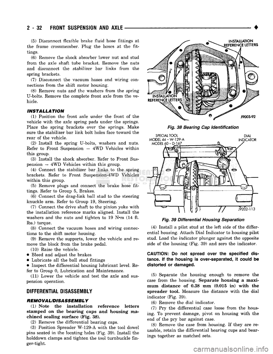
REMOVAL/DISASSEMBLY (1) Note the installation reference letters
stamped on the bearing caps and housing ma
chined sealing surface (Fig. 38). (2) Remove the differential bearing caps.
(3) Position Spreader W-129-A with the tool dowel
pins seated in the locating holes (Fig. 39). Install the
holddown clamps and tighten the tool turnbuckle fin ger-tight.
INSTALLATION
EFERENCE
LETTERS
J9003-92
Fig.
38 Bearing Cap
Identification
SPECIAL
TOOL
MODEL
44-W-129-A
MODEL
60-D-167
DIAL
INDICATOR
«ar"P—
J9202-113
Fig.
39
Differential
Housing
Separation
(4) Install a pilot stud at the left side of the differ
ential housing. Attach Dial Indicator to housing pilot stud. Load the indicator plunger against the opposite
side of the housing (Fig. 39) and zero the indicator.
CAUTION:
Do not
spread
over the specified
dis
tance.
If the
housing
is over-separated, it
could
be distorted or
damaged.
(5) Separate the housing enough to remove the
case from the housing. Separate housing a maxi
mum distance of 0.38 mm (0.015 in) with the spreader tool. Measure the distance with the dial
indicator (Fig. 39).
(6) Remove the dial indicator.
(7) Pry the differential case loose from the hous
ing. To prevent damage, pivot on housing with the end of the pry bar against case.
(8) Remove the case from housing. If they are re
usable, retain the differential bearing cups and bear ings together as matched sets.
Page 112 of 1502
•
TAPERED
BUSHING
J9202-53
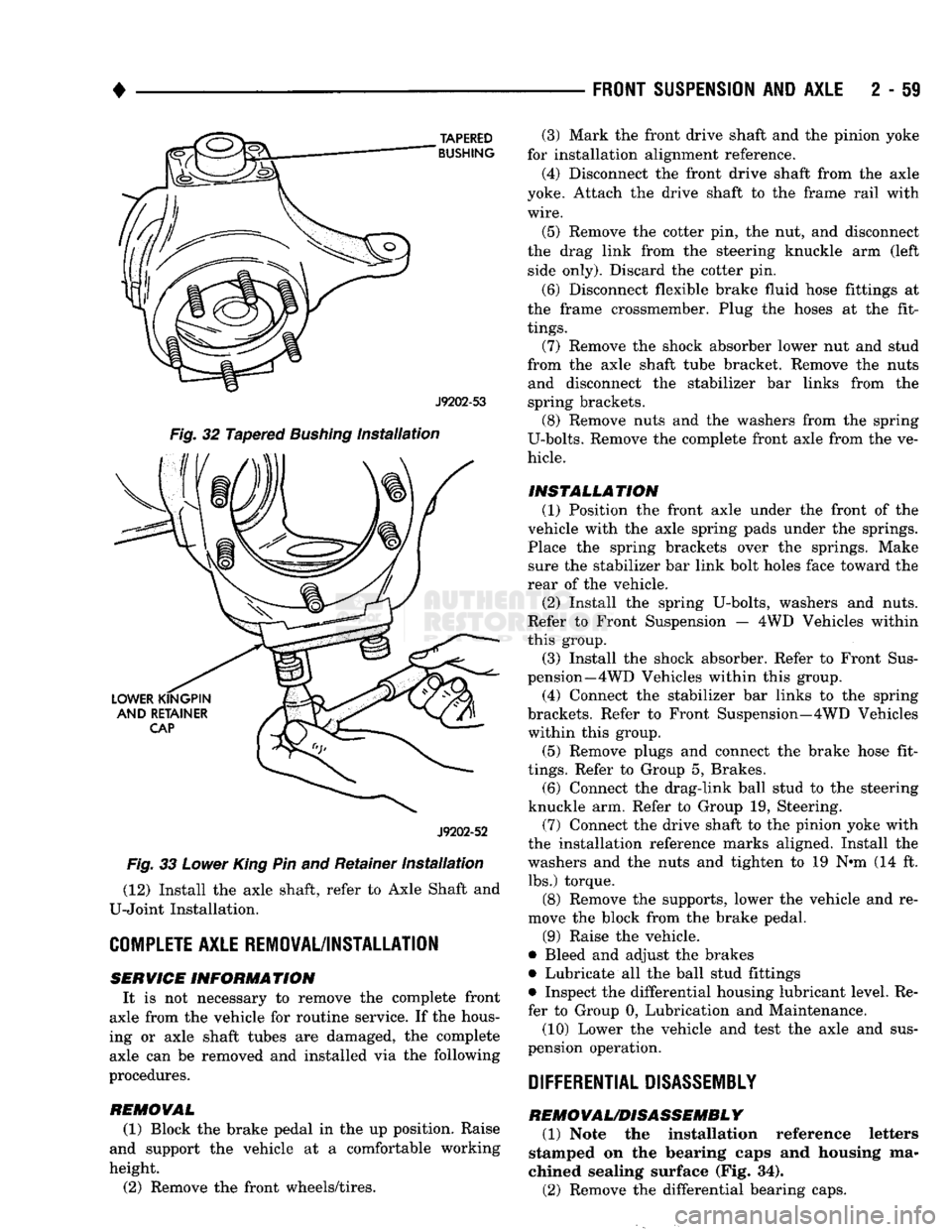
Fig.
32 Tapered
Bushing
Installation
J9202-52
Fig.
33
Lower
King
Pin and Retainer
Installation
(12) Install the axle shaft, refer to Axle Shaft and
U-Joint Installation.
COMPLETE
AXLE REMOVAL/INSTALLATION SERVICE
INFORMATION
It is not necessary to remove the complete front
axle from the vehicle for routine service. If the hous
ing or axle shaft tubes are damaged, the complete axle can be removed and installed via the following
procedures.
REMOVAL
(1) Block the brake pedal in the up position. Raise
and support the vehicle at a comfortable working
height.
(2) Remove the front wheels/tires.
FRONT SUSPENSION
AND
AXLE
2 - 59
(3) Mark the front drive shaft and the pinion yoke
for installation alignment reference.
(4) Disconnect the front drive shaft from the axle
yoke. Attach the drive shaft to the frame rail with
wire.
(5) Remove the cotter pin, the nut, and disconnect
the drag link from the steering knuckle arm (left side only). Discard the cotter pin.
(6) Disconnect flexible brake fluid hose fittings at
the frame crossmember. Plug the hoses at the fit
tings.
(7) Remove the shock absorber lower nut and stud
from the axle shaft tube bracket. Remove the nuts and disconnect the stabilizer bar links from the
spring brackets. (8) Remove nuts and the washers from the spring
U-bolts. Remove the complete front axle from the ve
hicle.
INSTALLATION (1) Position the front axle under the front of the
vehicle with the axle spring pads under the springs.
Place the spring brackets over the springs. Make sure the stabilizer bar link bolt holes face toward the
rear of the vehicle.
(2) Install the spring U-bolts, washers and nuts.
Refer to Front Suspension — 4WD Vehicles within
this group. (3) Install the shock absorber. Refer to Front Sus
pension—4 WD Vehicles within this group.
(4) Connect the stabilizer bar links to the spring
brackets. Refer to Front Suspension—4WD Vehicles within this group.
(5) Remove plugs and connect the brake hose fit
tings.
Refer to Group 5, Brakes. (6) Connect the drag-link ball stud to the steering
knuckle arm. Refer to Group 19, Steering. (7) Connect the drive shaft to the pinion yoke with
the installation reference marks aligned. Install the
washers and the nuts and tighten to 19 N-m (14 ft. lbs.) torque.
(8) Remove the supports, lower the vehicle and re
move the block from the brake pedal.
(9) Raise the vehicle.
• Bleed and adjust the brakes
• Lubricate all the ball stud fittings
• Inspect the differential housing lubricant level. Re
fer to Group 0, Lubrication and Maintenance.
(10) Lower the vehicle and test the axle and sus
pension operation.
DIFFERENTIAL DISASSEMBLY
REMOVAL/DISASSEMBLY
(1) Note the installation reference letters
stamped on the bearing caps and housing ma
chined sealing surface (Fig. 34).
(2) Remove the differential bearing caps.
Page 146 of 1502
•
REAR
SUSPENSION
AND
AXLE
3 - 11
ADAPTERS
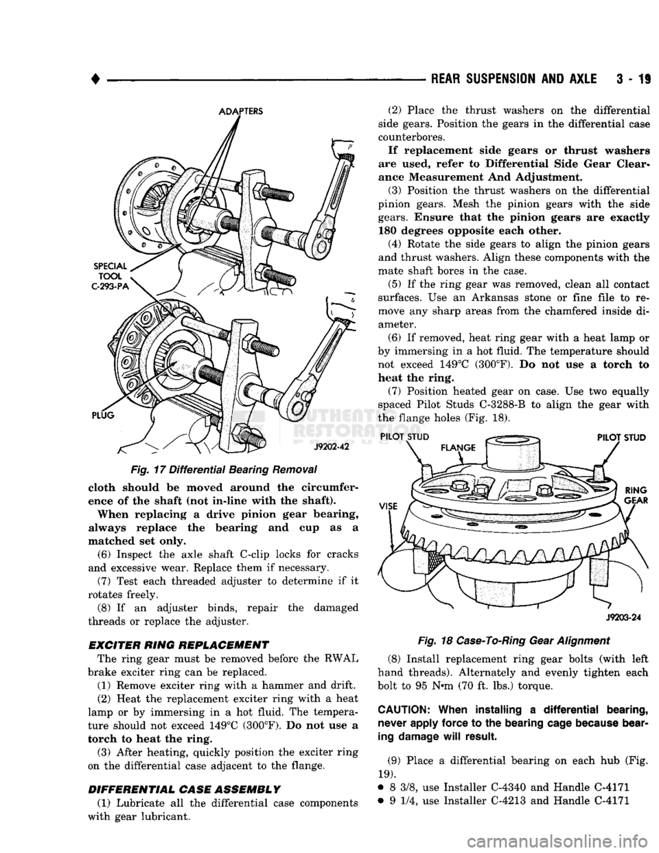
Fig.
17
Differential
Bearing
Removal
cloth should be moved around the circumfer
ence of the shaft (not in-line with the shaft).
When replacing a drive pinion gear bearing,
always replace the bearing and cup as a
matched set only.
(6) Inspect the axle shaft C-clip locks for cracks
and excessive wear. Replace them if necessary.
(7) Test each threaded adjuster to determine if it
rotates freely. (8) If an adjuster binds, repair the damaged
threads or replace the adjuster.
EXCITER
RING
REPLACEMENT
The ring gear must be removed before the RWAL
brake exciter ring can be replaced.
(1) Remove exciter ring with a hammer and drift.
(2) Heat the replacement exciter ring with a heat
lamp or by immersing in a hot fluid. The tempera
ture should not exceed 149°C (300°F). Do not use a
torch to heat the ring.
(3) After heating, quickly position the exciter ring
on the differential case adjacent to the flange.
DIFFERENTIAL
CASE ASSEMBLY
(1) Lubricate all the differential case components
with gear lubricant. (2) Place the thrust washers on the differential
side gears. Position the gears in the differential case
counterbores.
If replacement side gears or thrust washers
are used, refer to Differential Side Gear Clear ance Measurement And Adjustment.
(3) Position the thrust washers on the differential
pinion gears. Mesh the pinion gears with the side
gears.
Ensure that the pinion gears are exactly 180 degrees opposite each other.
(4) Rotate the side gears to align the pinion gears
and thrust washers. Align these components with the
mate shaft bores in the case.
(5) If the ring gear was removed, clean all contact
surfaces. Use an Arkansas stone or fine file to re
move any sharp areas from the chamfered inside di ameter.
(6) If removed, heat ring gear with a heat lamp or
by immersing in a hot fluid. The temperature should not exceed 149°C (300°F). Do not use a torch to
heat the ring.
(7) Position heated gear on case. Use two equally
spaced Pilot Studs C-3288-B to align the gear with
the flange holes (Fig. 18).
J9203-24
Fig.
18
Case-To-Ring
Gear
Alignment
(8) Install replacement ring gear bolts (with left
hand threads). Alternately and evenly tighten each
bolt to 95 N-m (70 ft. lbs.) torque.
CAUTION:
When
installing a
differential
bearing,
never apply force to the bearing
cage
because
bear
ing
damage
will
result.
(9) Place a differential bearing on each hub (Fig.
19).
• 8 3/8, use Installer C-4340 and Handle C-4171
• 9 1/4, use Installer C-4213 and Handle C-4171
Page 221 of 1502
5
- 34
BRAKES
•
boot
>TALLir TOOL
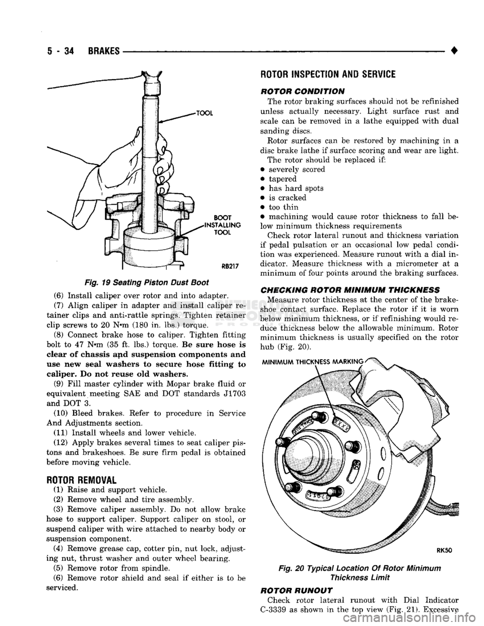
Fig.
19 Seating
Piston
Dust
Boot
(6) Install caliper over rotor and into adapter.
(7) Align caliper in adapter and install caliper re
tainer clips and anti-rattle springs. Tighten retainer clip screws to 20 N*m (180 in. lbs.) torque.
(8) Connect brake hose to caliper. Tighten fitting
bolt to 47 N»m (35 ft. lbs.) torque. Be sure hose is clear of chassis and suspension components and
use new seal washers to secure hose fitting to caliper. Do not reuse old washers.
(9) Fill master cylinder with Mopar brake fluid or
equivalent meeting SAE and DOT standards J1703 and DOT 3.
(10) Bleed brakes. Refer to procedure in Service
And Adjustments section.
(11) Install wheels and lower vehicle.
(12) Apply brakes several times to seat caliper pis
tons and brakeshoes. Be sure firm pedal is obtained
before moving vehicle.
ROTOR REMOVAL
(1) Raise and support vehicle.
(2) Remove wheel and tire assembly.
(3) Remove caliper assembly. Do not allow brake
hose to support caliper. Support caliper on stool, or suspend caliper with wire attached to nearby body or
suspension component. (4) Remove grease cap, cotter pin, nut lock, adjust
ing nut, thrust washer and outer wheel bearing. (5) Remove rotor from spindle.
(6) Remove rotor shield and seal if either is to be
serviced.
ROTOR
INSPECTION AND
SERVICE
rotor condition The rotor braking surfaces should not be refinished
unless actually necessary. Light surface rust and scale can be removed in a lathe equipped with dual
sanding discs.
Rotor surfaces can be restored by machining in a
disc brake lathe if surface scoring and wear are light.
The rotor should be replaced if:
• severely scored
• tapered
• has hard spots
• is cracked
• too thin • machining would cause rotor thickness to fall be
low minimum thickness requirements Check rotor lateral runout and thickness variation
if pedal pulsation or an occasional low pedal condi
tion was experienced. Measure runout with a dial in dicator. Measure thickness with a micrometer at a
minimum of four points around the braking surfaces.
CHECKING
ROTOR
MINIMUM
THICKNESS
Measure rotor thickness at the center of the brake-
shoe contact surface. Replace the rotor if it is worn
below minimum thickness, or if refinishing would re duce thickness below the allowable minimum. Rotor
minimum thickness is usually specified on the rotor
hub (Fig. 20).
Fig.
20 Typical Location Of Rotor
Minimum
Thickness
Limit
ROTOR RUNOUT Check rotor lateral runout with Dial Indicator
C-3339 as shown in the top view (Fig. 21). Excessive
Page 230 of 1502
•
BRAKES
5 - 43
CAMPER
ASSEMBLY
(1) Mount caliper in vise equipped with protective
jaws.
Do not overtighten vise. Excessive pressure could cause bore distortion and piston binding. (2) Lubricate new piston seal and piston bore with
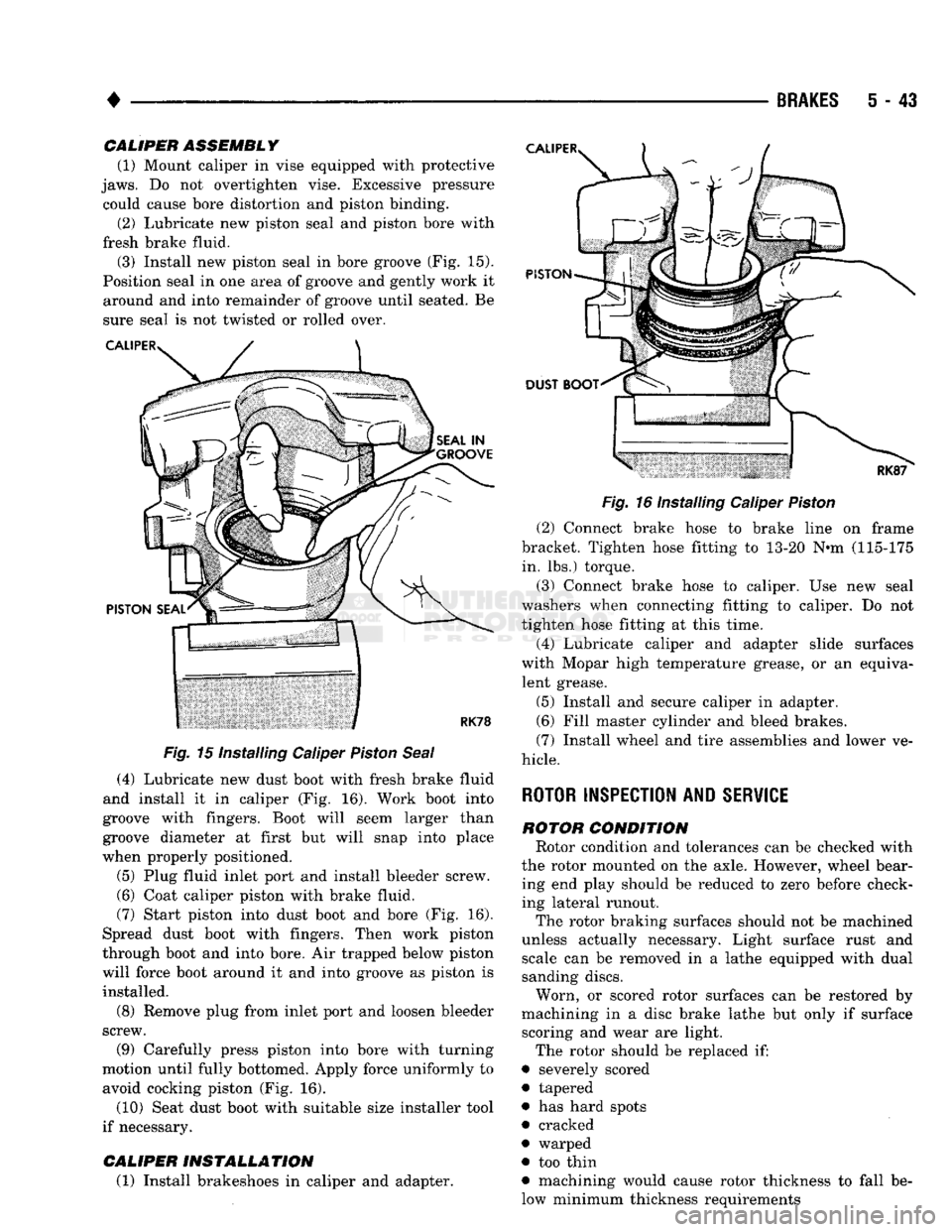
fresh brake fluid. (3) Install new piston seal in bore groove (Fig. 15).
Position seal in one area of groove and gently work it around and into remainder of groove until seated. Be
sure seal is not twisted or rolled over.
Fig.
15 Installing Caliper
Piston
Seal
(4) Lubricate new dust boot with fresh brake fluid
and install it in caliper (Fig. 16). Work boot into
groove with fingers. Boot will seem larger than
groove diameter at first but will snap into place
when properly positioned.
(5) Plug fluid inlet port and install bleeder screw. (6) Coat caliper piston with brake fluid.
(7) Start piston into dust boot and bore (Fig. 16).
Spread dust boot with fingers. Then work piston
through boot and into bore. Air trapped below piston
will force boot around it and into groove as piston is installed.
(8) Remove plug from inlet port and loosen bleeder
screw.
(9) Carefully press piston into bore with turning
motion until fully bottomed. Apply force uniformly to avoid cocking piston (Fig. 16).
(10) Seat dust boot with suitable size installer tool
if necessary.
CALIPER
INSTALLATION
(1) Install brakeshoes in caliper and adapter.
Fig.
16 Installing Caliper
Piston
(2) Connect brake hose to brake line on frame
bracket. Tighten hose fitting to 13-20 N«m (115-175 in. lbs.) torque.
(3) Connect brake hose to caliper. Use new seal
washers when connecting fitting to caliper. Do not
tighten hose fitting at this time.
(4) Lubricate caliper and adapter slide surfaces
with Mopar high temperature grease, or an equiva lent grease.
(5) Install and secure caliper in adapter.
(6) Fill master cylinder and bleed brakes.
(7) Install wheel and tire assemblies and lower ve
hicle.
ROTOR INSPECTION AND
SERVICE
ROTOR
CONDITION
Rotor condition and tolerances can be checked with
the rotor mounted on the axle. However, wheel bear ing end play should be reduced to zero before check
ing lateral runout.
The rotor braking surfaces should not be machined
unless actually necessary. Light surface rust and scale can be removed in a lathe equipped with dual
sanding discs.
Worn, or scored rotor surfaces can be restored by
machining in a disc brake lathe but only if surface scoring and wear are light.
The rotor should be replaced if:
• severely scored
• tapered
• has hard spots
• cracked
• warped
• too thin
• machining would cause rotor thickness to fall be
low minimum thickness requirements