1993 DODGE TRUCK washer fluid
[x] Cancel search: washer fluidPage 987 of 1502
19
-26
STEERING
•
CAUTION:
Do not
turn
stub
shaft
any
further
than
necessary.
The
recirculating
balls
will
drop
out of
the
rack
piston
circuit
and fall
inside
the
rack
pis
ton
chamber.
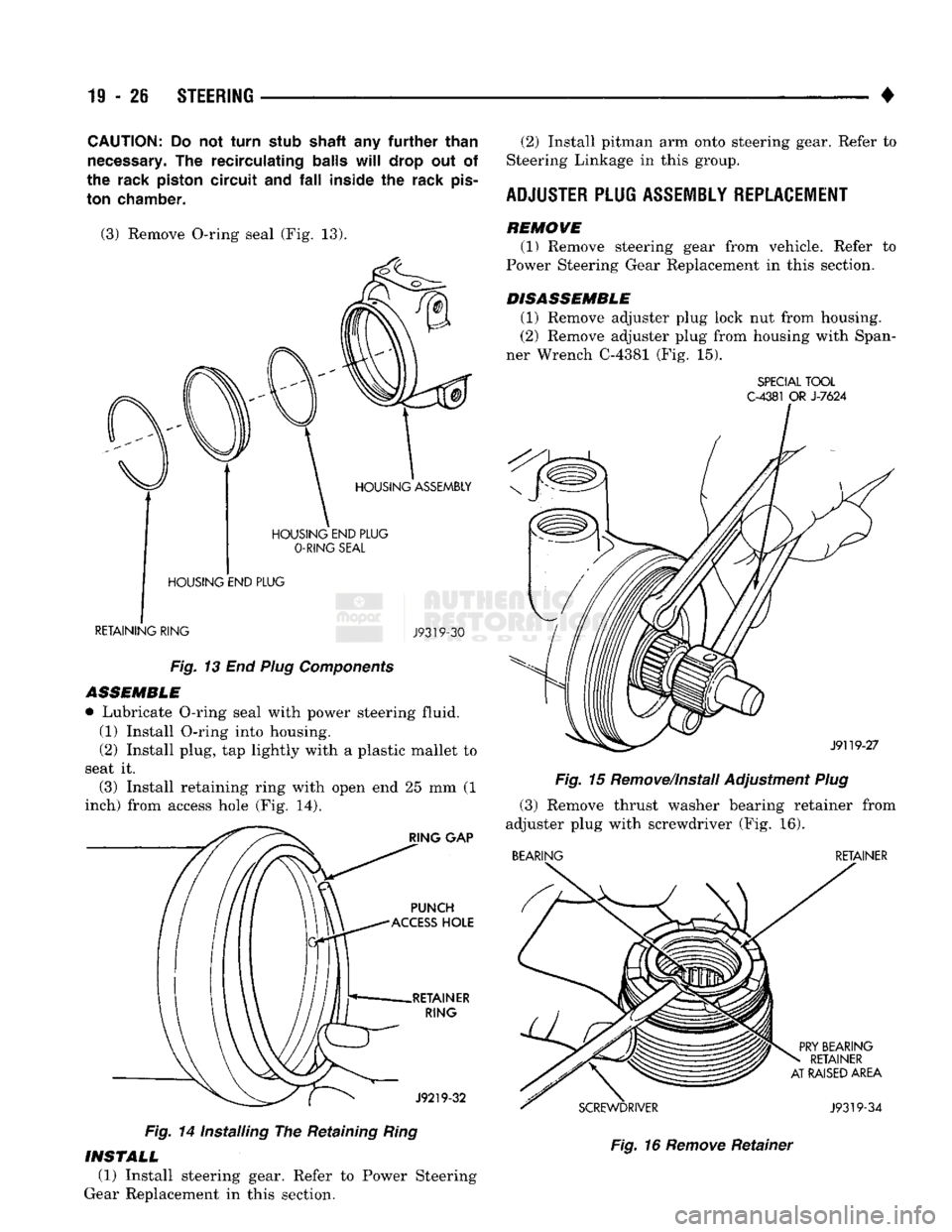
(3) Remove O-ring seal
(Fig. 13).
HOUSING
END
PLUG
O-RING
SEAL
HOUSING
END
PLUG
RETAINING
RING
J9319-30
Fig.
13 End
Plug
Components
ASSEMBLE
• Lubricate O-ring seal with power steering fluid. (1) Install O-ring into housing.
(2) Install plug,
tap
lightly with
a
plastic mallet
to
seat
it.
(3) Install retaining ring with open
end 25 mm (1
inch) from access hole
(Fig. 14).
Fig.
14
Installing
The
Retaining
Ring
(2) Install pitman
arm
onto steering gear. Refer
to
Steering Linkage
in
this group.
ADJUSTER
PLUG
ASSEMBLY
REPLACEMENT
REMOWE (1) Remove steering gear from vehicle. Refer
to
Power Steering Gear Replacement
in
this section.
DISASSEMBLE (1) Remove adjuster plug lock
nut
from housing.
(2) Remove adjuster plug from housing with Span
ner Wrench C-4381
(Fig. 15).
SPECIAL
TOOL
C-4381
OR
J-7624
Fig.
15
Remove/Install Adjustment
Plug
(3) Remove thrust washer bearing retainer from
adjuster plug with screwdriver
(Fig. 16).
BEARING
RETAINER
Fig.
16
Remove
Retainer
INSTALL
(1) Install steering gear. Refer
to
Power Steering
Gear Replacement
in
this section.
Page 995 of 1502
19
- 34
STEERING
• •
4WD vehicles; tighten gear frame reinforcement
bracket to frame bolts/nuts to 223 N-m (165 ft. lbs.)
torque.
(4) Align and install the pitman arm.
(5) Install the washer and retaining nut on the pit
man shaft. Tighten the nut to 251 N-m (185 ft. lbs.)
torque.
(6) Connect fluid hoses to steering gear, tighten to
28 N-m (21 ft. lbs.). Add fluid, refer to Power Steer
ing Pump Initial Operation.
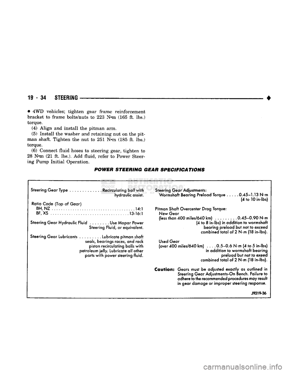
POWER STEERING GEAR SPECIFICATIONS
Steering Gear Type ............. Recirculating ball with hydraulic assist.
Ratio Code (Top
of
Gear) BH,NZ
14:1
BF,
XS 13-16:1
Steering Gear Hydraulic Fluid Use Mopar Power Steering Fluid,
or
equivalent.
Steering Gear Lubricants Lubricate pitman shaft
seals,
bearings races,
and
rack piston recirculating balls with
petroleum
jelly.
Lubricate all other parts with power steering fluid. Steering Gear Adjustments:
Wormshaft Bearing Preload Torque 0.45-1.13
Nm
(4
to
10 in-lbs)
Pitman Shaft Overcenter Drag Torque: New Gear
(less than 400 miles/640 km) ......... 0.45-0.90
Nm
(4
to 8
in-lbs)
in
addition
to
wormshaft bearing preload but not to exceed
combined total
of
2
Nm
(18 in-lbs).
Used Gear
(over 400 miles/640 km) 0.5-0.6
Nm
(4 to
5
in-lbs) in addition
to
wormshaft bearing preload but not to exeed
combined total
of
2 N-m (18 in-lbs).
Caution:
Gears must
be
adjusted exactly
as
outlined
in
Steering Gear Adjustments-On Bench. Failure
to
adhere
to
the recommended procedures may result
in gear damage
or
improper steering response.
J9219-36
Page 1139 of 1502
21
- 138
IN-VEHICLE SERVSCE-32RH/36RH/37RH/42RH/46RH
(2) Install and tighten gear-to-body bolts finger
tight. Make sure oil passage in governor body aligns
with matching passage in gear. (3) Install assembled governor body and gear on
output shaft.
(4) Position governor body so valve shaft hole in
body aligns with matching hole in output shaft. Then slide body and park gear into place. (5) Install snap ring securing governor and park
gear to output shaft (Fig. 22).
(6) Tighten bolts attaching governor body to park
gear to 11 N»m (95 in. lbs.) torque.
(7) Assemble governor weights and spring. Secure
inner weight and spring in outer weight with snap
ring (Fig. 21).
(8) Install weight assembly in governor body and
install retaining snap ring (Fig. 21).
(9) Place governor valve on valve shaft. Insert shaft
in governor body, through governor weights and output
shaft. Be sure valve is properly seated in body.
(10) Secure valve shaft with small snap ring.
(11) Install output shaft bearing and extension
housing. Refer to procedure in this section.
GOVERNOR
AND
PARK LOCK SERVICE—42RH/
46RH
The governor and park lock components are located
within the overdrive unit and cannot be serviced in
the vehicle. The overdrive unit must be removed and disassem
bled for access to the governor and park lock compo
nents.
Refer to the 42RH/46RH overdrive unit service sec
tions for repair procedures.
PARK
LOCK SERVICE—32RH/36RH/37RH
PARK LOCK
COMPONENT REMOVAL
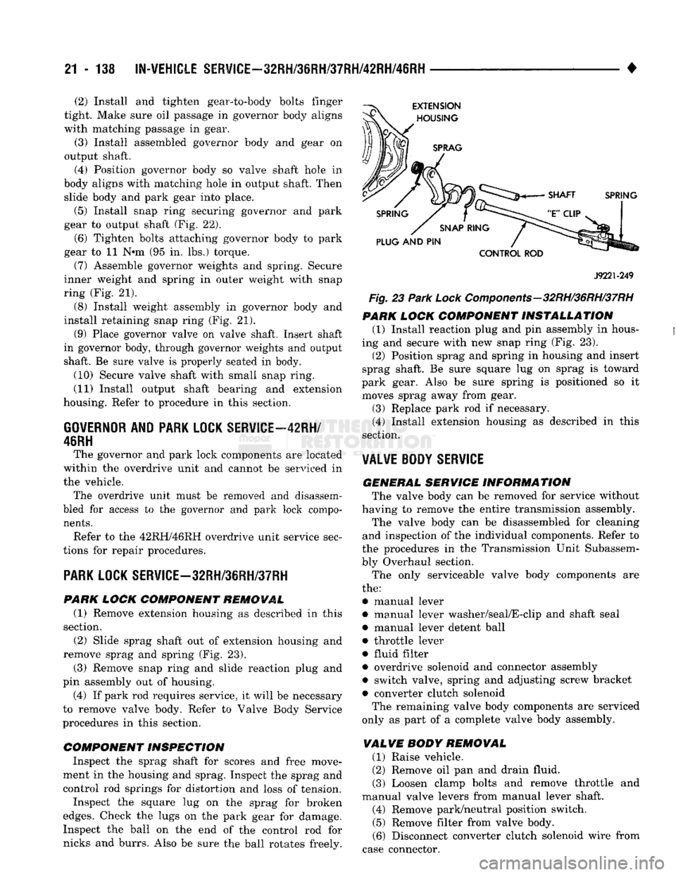
(1) Remove extension housing as described in this
section. (2) Slide sprag shaft out of extension housing and
remove sprag and spring (Fig. 23).
(3) Remove snap ring and slide reaction plug and
pin assembly out of housing. (4) If park rod requires service, it will be necessary
to remove valve body. Refer to Valve Body Service
procedures in this section.
COMPONENT INSPECTION
Inspect the sprag shaft for scores and free move
ment in the housing and sprag. Inspect the sprag and control rod springs for distortion and loss of tension.
Inspect the square lug on the sprag for broken
edges.
Check the lugs on the park gear for damage. Inspect the ball on the end of the control rod for
nicks and burrs. Also be sure the ball rotates freely.
J9221-249
Fig. 23
Park
Lock Components-32RH/36RH/37RH
PARK
LOCK
COMPONENT INSTALLATION
(1) Install reaction plug and pin assembly in hous
ing and secure with new snap ring (Fig. 23).
(2) Position sprag and spring in housing and insert
sprag shaft. Be sure square lug on sprag is toward
park gear. Also be sure spring is positioned so it moves sprag away from gear.
(3) Replace park rod if necessary. (4) Install extension housing as described in this
section.
VALVE BODY
SERVICE
GENERAL SERVICE
INFORMATION
The valve body can be removed for service without
having to remove the entire transmission assembly. The valve body can be disassembled for cleaning
and inspection of the individual components. Refer to
the procedures in the Transmission Unit Subassem
bly Overhaul section.
The only serviceable valve body components are
the:
• manual lever
• manual lever washer/seal/E-clip and shaft seal
• manual lever detent ball
• throttle lever
• fluid filter
• overdrive solenoid and connector assembly
• switch valve, spring and adjusting screw bracket • converter clutch solenoid The remaining valve body components are serviced
only as part of a complete valve body assembly.
VALVE
BODY
REMOVAL
(1) Raise vehicle.
(2) Remove oil pan and drain fluid.
(3) Loosen clamp bolts and remove throttle and
manual valve levers from manual lever shaft. (4) Remove park/neutral position switch. (5) Remove filter from valve body.
(6) Disconnect converter clutch solenoid wire from
case connector.
Page 1159 of 1502
21 - 158
TRANSMISSION
OVERHAUL—32RH
•
OVERHAUL SERVICE
INFORMATION
Inspect all the transmission bushings during over
haul. Bushing condition is important as worn, scored
bushings contribute to low pressures, clutch slip and accelerated wear of other components. Do not replace
bushings as a matter of course. Replace bushings
only when actually worn or scored. Use recommended tools to replace bushings. The
tools are sized and designed to remove, install and seat bushings correctly, The bushing replacement
tools are included in Bushing Tool Set C-3887-B. The
tool set is manufactured by the Miller Tool Co. and is available through the dealer tool program. Pre-sized service bushings are available for re
placement purposes. Only the sun gear bushings are
not serviced. Low cost of the sun gear assembly
makes it easier to simply replace the gear and bush
ings as an assembly. Heli-Coil inserts are recommended for repairing
damaged, stripped or worn threads in aluminum
parts.
These inserts are available from most automo
tive jobbers. Stainless steel inserts are preferred. The use of crocus cloth is permissible where neces
sary, providing it is used carefully. When used on
valves, use extreme care to avoid rounding off sharp
edges.
Sharp edges are vital as they prevent foreign
matter from getting between the valve and valve
bore.
Do not reuse oil seals, gaskets, seal rings, or
O-rings during overhaul. Replace these parts as a
matter of course. Also do not reuse snap rings or
E-clips that are bent or distorted. Replace these parts as well.
Lubricate transmission parts with Mopar ATF
Plus,
Type 7176, or Dexron II™ transmission fluid during overhaul and assembly.
Use Ru-Glyde or Door Eze to lubricate clutch pis
ton seals. Use petroleum jelly to lubricate O-rings and thrust washers. Petroleum jelly can also be used
to hold parts in place during reassembly.
TRANSMISSION
CASE
CLEAN1N8
AND
INSPECTION
Clean the case in a solvent tank. Flush the case
bores and fluid passages thoroughly with solvent. Dry the case and all fluid passages with compressed
air. Be sure all solvent is removed from the case and
that all fluid passages are clear. Do not use shop towels or rags to dry the case
(or any other transmission component) unless
they are made from lint-free materials. Lint will
readily adhere to case surfaces and transmission
components and will circulate throughout the
transmission after assembly. A sufficient quan
tity of lint can block fluid passages and interfere
with valve body operation. Inspect the case for cracks, porous spots, worn
bores,
or damaged threads. Damaged threads can be repaired with Helicoil thread inserts. However, the
case will have to be replaced if it exhibits any type of
damage or wear.
Lubricate the front band adjusting screw threads
with petroleum jelly and thread the screw part-way into the case. Be sure the screw turns freely.
Remount the case in Repair Stand C-3750-B after
cleaning and inspection.
OVERRUNNING CLUTCH-LOW-REVERSE
DRUM-REAR
SUPPORT OVERHAUL
DISASSEMBLING OVERRUNNING CLUTCH/ LOW-REVERSE DRUM
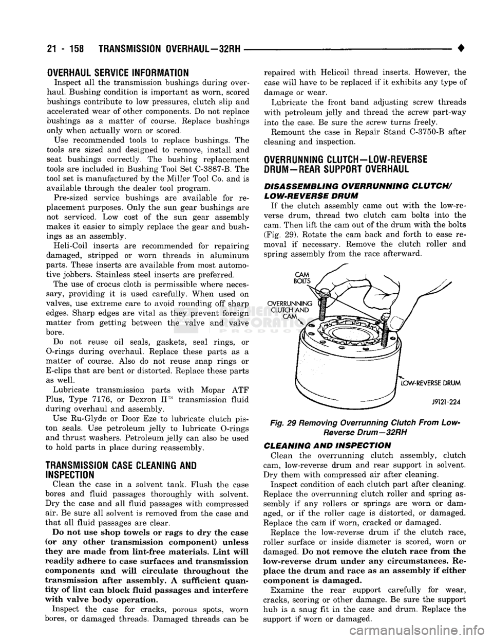
If the clutch assembly came out with the low-re
verse drum, thread two clutch cam bolts into the cam. Then lift the cam out of the drum with the bolts (Fig. 29). Rotate the cam back and forth to ease re
moval if necessary. Remove the clutch roller and spring assembly from the race afterward.
Fig, 29 Removing Overrunning Clutch From Low- Reverse Drum—32RH
CLEANING AND INSPECTION Clean the overrunning clutch assembly, clutch
cam, low-reverse drum and rear support in solvent.
Dry them with compressed air after cleaning. Inspect condition of each clutch part after cleaning.
Replace the overrunning clutch roller and spring as sembly if any rollers or springs are worn or dam
aged, or if the roller cage is distorted, or damaged.
Replace the cam if worn, cracked or damaged.
Replace the low-reverse drum if the clutch race,
roller surface or inside diameter is scored, worn or damaged. Do not remove the clutch race from the
low-reverse drum under any circumstances. Re place the drum and race as an assembly if either component is damaged.
Examine the rear support carefully for wear,
cracks, scoring or other damage. Be sure the support
hub is a snug fit in the case and drum. Replace the support if worn or damaged.
Page 1165 of 1502
21
- 164
TRANSMISSION
OVERHAUL—32RH
•
SPECIAL TOOL
C-4171
PUMP
HOUSING
BUSHING
REMOVAL
SPECIAL TOOL
C-4171
SPECIAL
TOOL
SP-3551
BUSHING
SPECIAL TOOL
SP-5117
BUSHING
J9221-242
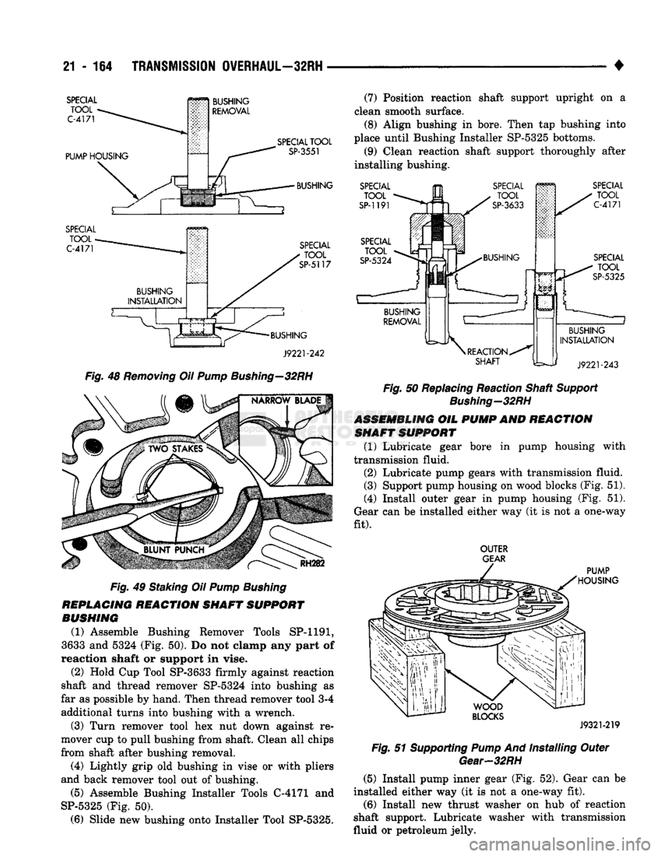
Fig.
48
Removing
OH
Pump
Bushing—32RH
RH282
Fig.
49 Staking Oil
Pump
Bushing
REPLACING
REACTION
SHAFT
SUPPORT
BUSHING
(1) Assemble Bushing Remover Tools SP-1191,
3633 and 5324 (Fig. 50). Do not clamp any part of
reaction shaft or support in vise.
(2) Hold Cup Tool SP-3633 firmly against reaction
shaft and thread remover SP-5324 into bushing as
far as possible by hand. Then thread remover tool 3-4 additional turns into bushing with a wrench.
(3) Turn remover tool hex nut down against re
mover cup to pull bushing from shaft. Clean all chips
from shaft after bushing removal.
(4) Lightly grip old bushing in vise or with pliers
and back remover tool out of bushing.
(5) Assemble Bushing Installer Tools C-4171 and
SP-5325 (Fig. 50). (6) Slide new bushing onto Installer Tool SP-5325. (7) Position reaction shaft support upright on a
clean smooth surface. (8) Align bushing in bore. Then tap bushing into
place until Bushing Installer SP-5325 bottoms.
(9) Clean reaction shaft support thoroughly after
installing bushing.
SPECIAL
TOOL
SP-1191 SPECIAL
TOOL
C-4171
SPECIAL
_ U TQQL
SP-5325
BUSHING
INSTALLATION
J9221-243
Fig.
50 Replacing Reaction Shaft
Support
Bushing—32RH
ASSEMBLING
OIL
PUMP
AND
REACTION
SHAFT
SUPPORT
(1) Lubricate gear bore in pump housing with
transmission fluid.
(2) Lubricate pump gears with transmission fluid.
(3) Support pump housing on wood blocks (Fig. 51).
(4) Install outer gear in pump housing (Fig. 51).
Gear can be installed either way (it is not a one-way
fit).
OUTER
GEAR
PUMP
HOUSING
WOOD
BLOCKS
J9321-219
Fig.
51 Supporting
Pump
And Installing Outer
Gear-32RH
(5) Install pump inner gear (Fig. 52). Gear can be
installed either way (it is not a one-way fit). (6) Install new thrust washer on hub of reaction
shaft support. Lubricate washer with transmission
fluid or petroleum jelly.
Page 1169 of 1502
21-168
TRANSMISSION
OVERHAUL—32RH
REAR
CLUTCH PISTON CLUTCH
PISTON
SEALS
OUTPUT
SHAFT
THRUST
WASHER
(METAL) INPUT
SHAFT
SNAP
RING
REAR
CLUTCH
RETAINER INPUT
SHAFT
-REAR
CLUTCH
.
THRUST
" /
SHAFT WASHER
/
FRONT
('I"")
SHAFT SEAL
REAR
RING
rniTru
SEAL
(TEFLON)
C^TCH
RING PACK
SNAP
RING
(SELECTIVE)
PISTON
SPRING
BOTTOM
PRESSURE
PLATE CLUTCH
DISCS
(4)
TOP
PRESSURE
PLATE
J9121-539
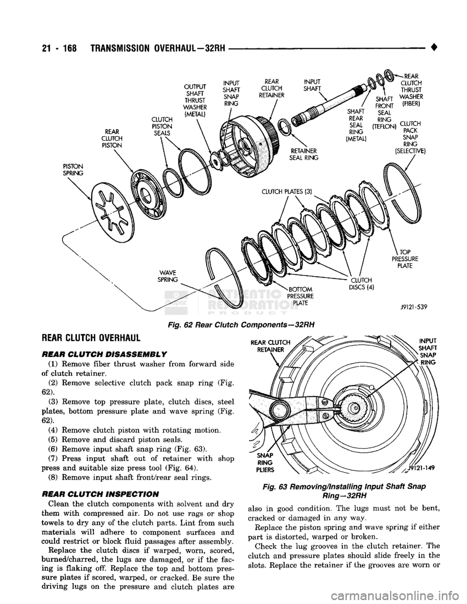
Fig.
62 Rear
Clutcl
REAR
CLUTCH OVERHAUL
REAR
CLUTCH DISASSEMBLY
(1) Remove fiber thrust washer from forward side
of clutch retainer. (2) Remove selective clutch pack snap ring (Fig.
62).
(3) Remove top pressure plate, clutch discs, steel
plates,
bottom pressure plate and wave spring (Fig.
62).
(4) Remove clutch piston with rotating motion.
(5) Remove and discard piston seals.
(6) Remove input shaft snap ring (Fig. 63). (7) Press input shaft out of retainer with shop
press and suitable size press tool (Fig. 64).
(8) Remove input shaft front/rear seal rings.
REAR
CLUTCH INSPECTION
Clean the clutch components with solvent and dry
them with compressed air. Do not use rags or shop
towels to dry any of the clutch parts. Lint from such materials will adhere to component surfaces and
could restrict or block fluid passages after assembly.
Replace the clutch discs if warped, worn, scored,
burned/charred, the lugs are damaged, or if the fac ing is flaking off. Replace the top and bottom pressure plates if scored, warped, or cracked. Be sure the
driving lugs on the pressure and clutch plates are
Components—32
RH
Fig.
63 Removing/Installing Input Shaft
Snap
Ring-32RH
also in good condition. The lugs must not be bent,
cracked or damaged in any way. Replace the piston spring and wave spring if either
part is distorted, warped or broken. Check the lug grooves in the clutch retainer. The
clutch and pressure plates should slide freely in the
slots.
Replace the retainer if the grooves are worn or
Page 1170 of 1502
•
TRANSMISSION
OVERHAUL—32RH
21 - 111
J9121-150
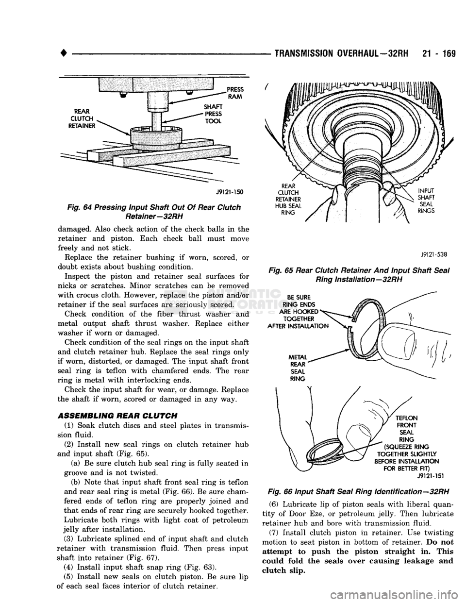
Fig. 64 Pressing input Shaft Out Of Rear Clutch Retainer—32RH damaged. Also check action of the check balls in the
retainer and piston. Each check ball must move
freely and not stick.
Replace the retainer bushing if worn, scored, or
doubt exists about bushing condition.
Inspect the piston and retainer seal surfaces for
nicks or scratches. Minor scratches can be removed
with crocus cloth. However, replace the piston and/or
retainer if the seal surfaces are seriously scored.
Check condition of the fiber thrust washer and
metal output shaft thrust washer. Replace either
washer if worn or damaged.
Check condition of the seal rings on the input shaft
and clutch retainer hub. Replace the seal rings only
if worn, distorted, or damaged. The input shaft front seal ring is teflon with chamfered ends. The rear
ring is metal with interlocking ends.
Check the input shaft for wear, or damage. Replace
the shaft if worn, scored or damaged in any way.
ASSEMBLING REAR
CLUTCH
(1) Soak clutch discs and steel plates in transmis
sion fluid.
(2)
Install new seal rings on clutch retainer hub
and input shaft (Fig. 65).
(a) Be sure clutch hub seal ring is fully seated in
groove and is not twisted.
(b) Note that input shaft front seal ring is teflon
and rear seal ring is metal (Fig. 66). Be sure cham
fered ends of teflon ring are properly joined and
that ends of rear ring are securely hooked together. Lubricate both rings with light coat of petroleum
jelly after installation.
(3) Lubricate splined end of input shaft and clutch
retainer with transmission fluid. Then press input shaft into retainer (Fig. 67).
(4)
Install input shaft snap ring (Fig. 63).
(5) Install new seals on clutch piston. Be sure lip
of each seal faces interior of clutch retainer.
J9121
-538
Fig.
65 Rear Clutch Retainer And input Shaft
Seal Ring
Installation—32RH
J912M51 Fig. 66 input Shaft Seal
Ring
Identification—32RH
(6) Lubricate lip of piston seals with liberal quan
tity of Door Eze, or petroleum jelly. Then lubricate
retainer hub and bore with transmission fluid. (7) Install clutch piston in retainer. Use twisting
motion to seat piston in bottom of retainer. Do not attempt to push the piston straight in. This
could fold the seals over causing leakage and
clutch slip.
Page 1172 of 1502
TRANSMISSION
OVERHAUL—32RH
21 - 171
PLANETARY GEAR TRAIN
OVERHAUL
•OUTPUT
SHAFT
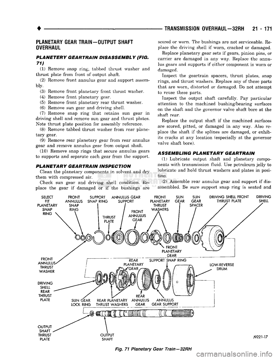
PLANETERY GEARTRAIN DISASSEMBLY (FIG.
71) (1) Remove snap ring, tabbed thrust washer and
thrust plate from front of output shaft.
(2) Remove front annulus gear and support assem
bly.
(3) Remove front planetary front thrust washer.
(4) Remove front planetary gear.
(5) Remove front planetary rear thrust washer.
(6) Remove sun gear and driving shell.
(7) Remove snap ring that retains sun gear in
driving shell and remove sun gear and thrust plates.
Note thrust plate position for assembly reference. (8) Remove tabbed thrust washer from rear plane
tary gear. (9) Remove rear planetary gear from rear annulus
gear and remove annulus gear from output shaft. (10) Remove snap rings that secure annulus gears
to supports and separate each gear from the support.
PLANETARY GEARTRAIN INSPECTION Clean the planetary components in solvent and dry
them with compressed air.
Check sun gear and driving shell condition. Re
place the gear if damaged or if the bushings are scored or worn. The bushings are not serviceable. Re
place the driving shell if worn, cracked or damaged. Replace planetary gear sets if gears, pinion pins, or
carrier are damaged in any way. Replace the annu
lus gears and supports if either component is worn or
damaged.
Inspect the geartrain spacers, thrust plates, snap
rings,
and thrust washers. Replace any of these parts
that are worn, distorted or damaged. Do not attempt
to reuse these parts.
Inspect the output shaft carefully. Pay particular
attention to the machined bushing/bearing surfaces
on the shaft and the governor valve shaft bore at the
shaft rear.
Replace the output shaft if the machined surfaces
are scored, pitted, or damaged in any way. Also re
place the shaft if the splines are damaged, or exhib its cracks at any location (especially at the governor
valve shaft bore).
ASSEMBLING PLANETARY GEARTRAIN
(1)
Lubricate output shaft and planetary compo
nents with transmission fluid. Use petroleum jelly to
lubricate and hold thrust washers and plates in posi
tion.
(2) Assemble rear annulus gear and support if dis
assembled. Be sure support snap ring is seated and
SELECT
FIT
PLANETARY
SNAP
RING FRONT
ANNULUS
SNAP
RING SUPPORT ANNULUS GEAR
SNAP
RING SUPPORT FRONT
PLANETARY THRUST
WASHERS
SUN
GEAR
SUN
GEAR
SPACER
DRIVING SHELL FRONT DRIVING
THRUST PLATE SHELL
FRONT
ANNULUS. THRUST
WASHER
DRIVING
SHELL
REAR
THRUST PLATE
OUTPUT
SHAFT
THRUST PLATE
OUTPUT
SHAFT
J9221-17
Fig.
71 Planetary Gear Train—32RH