1993 DODGE TRUCK heater
[x] Cancel search: heaterPage 33 of 1502

0 - 14
LUBRICATION
AND
MAINTENANCE
•
ENGINE
MAINTENANCE
INDEX
page
Air
Injection
Systems/Air Pump
. 17
Air-Conditioner
Compressor
21
Battery
19
Cooling System
15
Crankcase
Ventilation
System
17
Diesel Engine
Air Filter
Canister
17
Drive Belts
20
Engine
Air
Cleaner
Filter
Element
16
Engine Break-In
14
Engine
Oil 14
Engine
Oil
Change
and Filter
Replacement
15
Exhaust Gas
Recirculation
(EGR) System
...... 19
page
Exhaust
Manifold
Heat
Control
Valve
. 17
Exhaust System
, 21
Fuel System
18
Hoses
and
Fittings
16
Ignition
Cables,
Distributor
Cap and
Rotor
...... 19
Ignition
Timing
. 19
Oxygen
(02)
Sensor
19
Rubber/Plastic Components
20
Spark Plugs
. 19
Throttle
Control
Linkage
18
Vacuum Operated, Emission
Control
Components
19
ENGINE BREAK-IN
After first starting a new engine, allow it to idle
for 15 seconds before shifting into a drive gear. Also:
• Drive the vehicle at varying speeds less than 88
km/h (55 mph) for the first 480 km (300 miles).
• Avoid fast acceleration and sudden stops.
• Do not drive at full-throttle for extended periods of
time
• Do not drive at constant speeds
• Do not idle the engine excessively A special break-in engine oil is not required. The
original engine oil installed is a high quality lubri
cant. New engines tend to consume more fuel and oil un
til after the break-in period has ended.
ENGINE
OIL SPECIFICATIONS
API SERWICE
GRADE
Use an engine oil that conforms to API Service
Grade S5 SG/CD or SG/CE. MOPAR®provides engine
oils that conform to all of these service grades.
SULFATED ASH—DIESEL ENGINES
Oils that contain an excessive amount of sulfated
ash can cause deposits to develop on Diesel engine
valves. These deposits can result in valve wear.
SAE
WISC0SITY
An SAE viscosity grade is used to specify the vis
cosity of engine oil. SAE 30 specifies a single viscos
ity engine oil.
Engine oils also have multiple viscosities. 10W-30
<
5W-30
1
1 1
F
-20 0 10 20 32 60 80 100
C
-29 -18 -12 -7 0 16 27 38
ANTICIPATED
TEMPERATURE RANGE BEFORE
NEXT
OIL
CHANGE
J9000-39
Fig.
1 Temperature/Engine Oil Viscosity—Gasoline
Engines
-12°C
-18°C 10°F
0°F- 15W-40
-23°c(^-10eF
I
10W-30
WITH
WITHOUT
BLOCK HEATER
BLOCK
SYNTHETIC
OIL
HEATER
10W-30 5W-30
J9100-29
Fig.
2 Temperature/Engine Oil Viscosity—Diesel
Engines
ENERGY
G0NSERWING
OIL
An Energy Conserving type oil is recommended for
gasoline engines. They are designated as either EN
ERGY CONSERVING or ENERGY CONSERVING
II.
OIL
LEVEL
INDICATOR (DIPSTICK)
GASOLINE ENGINES
The engine oil indicator is located at the right
front of the engine.
Page 40 of 1502
•
LUBRICATION
AND
MAINTENANCE
0 - 21 ROUTINE INSPECTION
It is recommended that the drive belt(s) be rou
tinely inspected for cracks, fraying and excessive
wear. Replace as necessary.
EXHAUST SYSTEM
An exhaust system must be properly aligned to
prevent stress, leakage, and vehicle body contact.
MAINTENANCE SCHEDULE Inspect the exhaust system at the interval specified
in maintenance schedule.
INSPECTION Inspect for cracked or loose joints, corrosion dam
age,
and worn or broken hangers. Replace all compo
nents that are damaged. Do not attempt repair. Also,
inspect for the following conditions and correct as
necessary:
• Exhaust system leaks, misalignment • Contact with body panels or the frame
• Catalytic converter bulging or excessive heat dam
age
CAUTION:
A
catalytic converter
will
become
con
taminated
if
leaded gasoline
is
burned
in the en
gine.
If
this
occurs,
the
complete converter must
be
replaced.
AIR-CONDITIONER COMPRESSOR LUBRICANT
AND
REFRIGERANT
The lubricant level in the compressor should be
checked if there are indications that oil was lost.
Loss of lubricating oil usually accompanies a loss of
refrigerant. The presence of bubbles in sight glass in dicates that loss of refrigerant has occurred. For additional information involving the A/C sys
tem, refer to Group 24—Heater And Air Condition ing.
Page 272 of 1502
COOLING SYSTEM
CONTENTS page
DIAGNOSIS
... 4
ENGINE
ACCESSORY
DRIVE BELTS
40
ENGINE
BLOCK HEATERS
48
GENERAL
INFORMATION
Throughout this group, references are made to partic
ular vehicle models by alphabetical designation or by
the particular vehicle nameplate. A chart showing a
breakdown of alphabetical designations is included in
the Introduction section at the beginning of this man
ual.
5.9L gas powered engines will be' referred to as ei
ther: LDC (Light Duty Cycle) or HDC (Heavy Duty
Cycle).
COOLING
SYSTEM
The cooling system regulates engine operating tem
perature. It allows the engine to reach normal oper-
page
SERVICE
PROCEDURES
15
SPECIFICATIONS
; 49
ating temperature as quickly as possible. It also
maintains normal operating temperature and pre
vents overheating.
The cooling system also provides a means of heat
ing the passenger compartment and cooling the auto
matic transmission fluid (if equipped). The cooling system is pressurized and uses a centrifugal water
pump to circulate coolant throughout the system.
An optional factory installed maximum duty cool
ing package is available on most models. This pack age will provide additional cooling capacity for
vehicles used under extreme conditions such as
trailer towing in high ambient temperatures.
NOTE: HEATER
COOLANT FLOW
CIRCUIT
IS
ALWAYS
OPEN
EXCEPT
WHEN
IN MAX. A/C
OR
OFF
MODES
HEATER
INTAKE MANIFOLD
COOLANT FLOW "METERED" FROM REAR
TO
FRONT
AND
BELOW EXHAUST
HEAT
CROSSOVER
SHUT
OFF
VALVE
A/C
ONLY COOLANT FLOW
-
PUMP
TO
CYLINDER BLOCK,
UP
THROUGH CYLINDER HEADS
TO
INTAKE MANIFOLD WATER
BOX TO
RADIATOR-TO PUMP
•BYPASS
THERMOSTAT CLOSED-HIGH FLOW
THERMOSTAT OPEN
- LOW
FLOW
J9207-18
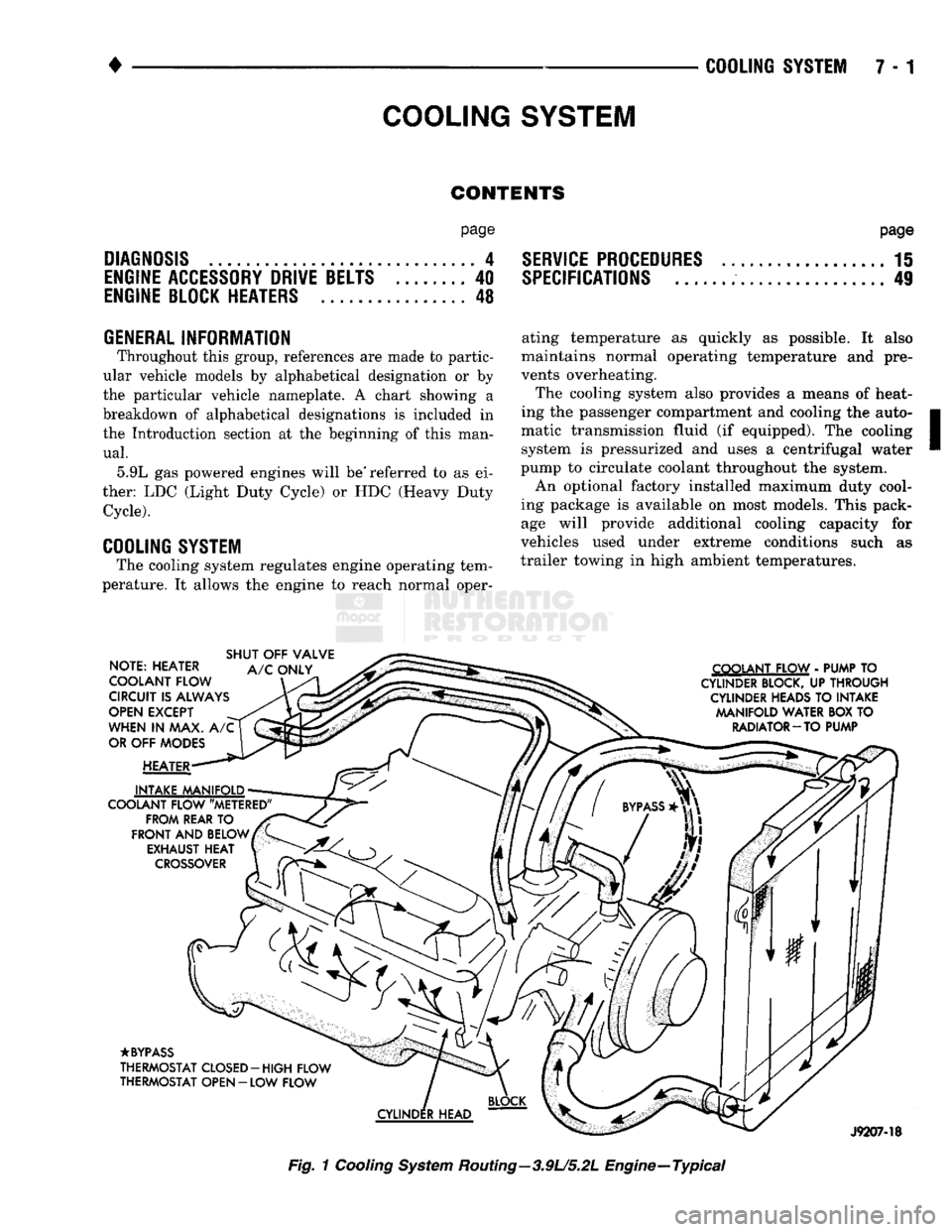
Fig.
1
Cooling
System
Routing—3.9U5.2L Engine—Typical
Page 273 of 1502
7 - 2
COOLING
SYSTEM
•
NOTE: HEATER
COOLANT FLOW
CIRCUIT
IS
ALWAYS
OPEN
EXCEPT
WHEN
IN MAX. A/C
OR
OFF
MODES
HEATER
INTAKE MANIFOLD
COOLANT FLOW "METERED" FROM REAR
TO
FRONT
AND
BELOW EXHAUST HEAT
CROSSOVER
SHUT
OFF
VALVE
A/C
ONLY COOLANT FLOW
-
PUMP
TO
CYLINDER
BLOCK,
UP
THROUGH
CYLINDER
HEADS
TO
INTAKE MANIFOLD WATER BOX
TO
RADIATOR
—
TO PUMP
•BYPASS
THERMOSTAT CLOSED-HIGH FLOW
THERMOSTAT OPEN
-
LOW FLOW
CYLINDER
HEAD
RR07B52
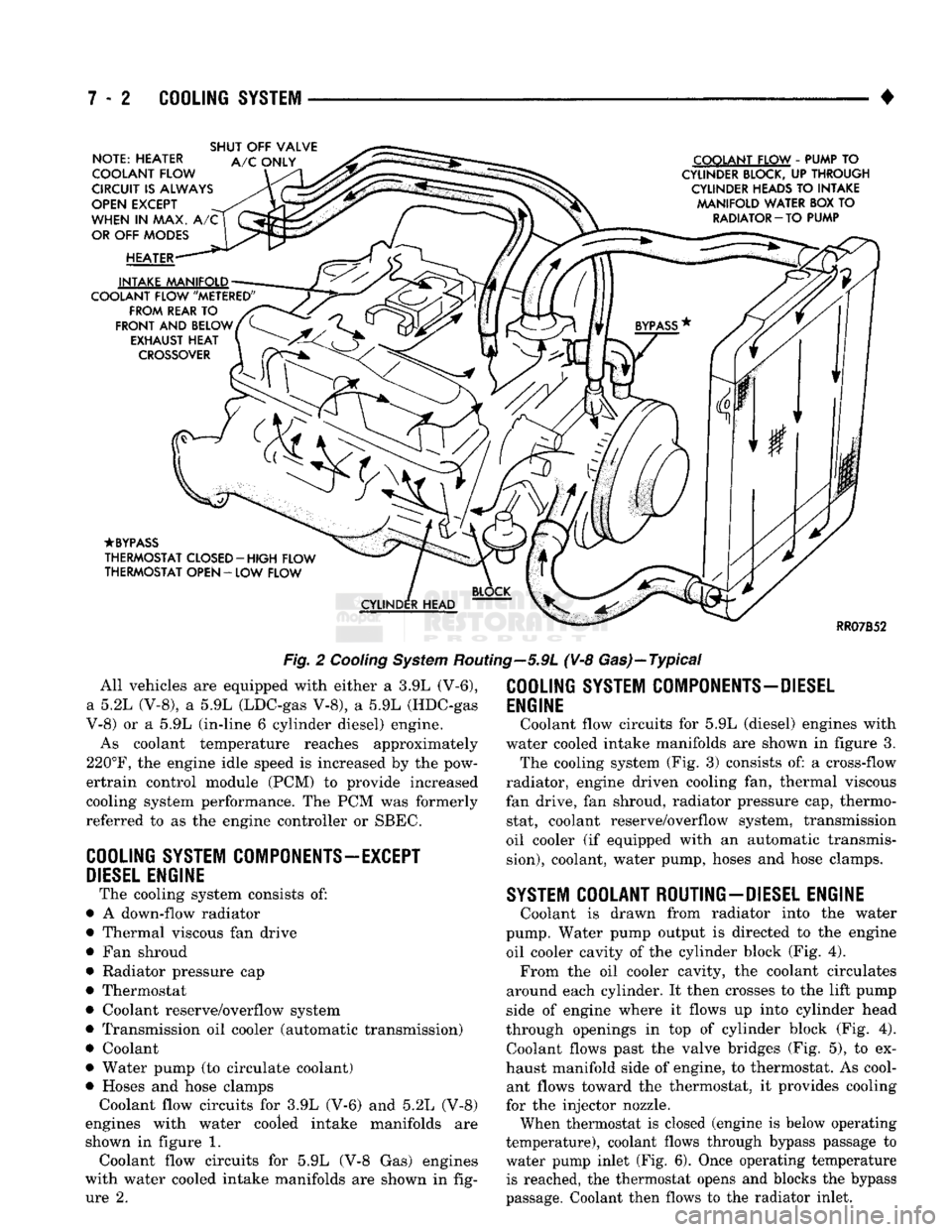
Fig.
2
Cooling
System
Routing—5.9L (V-8 Gas)—Typical All vehicles are equipped with either a 3.9L (V-6),
a 5.2L (V-8), a 5.9L (LDC-gas V-8), a 5.9L (HDC-gas
V-8) or a 5.9L (in-line 6 cylinder diesel) engine.
As coolant temperature reaches approximately
220°F,
the engine idle speed is increased by the pow-
ertrain control module (PCM) to provide increased
cooling system performance. The PCM was formerly
referred to as the engine controller or SBEC.
COOLING
SYSTEM
COMPONENTS—EXCEPT
DIESEL
ENGINE
The cooling system consists of:
• A down-flow radiator
• Thermal viscous fan drive
• Fan shroud
• Radiator pressure cap
• Thermostat
• Coolant reserve/overflow system
• Transmission oil cooler (automatic transmission)
• Coolant
• Water pump (to circulate coolant)
• Hoses and hose clamps Coolant flow circuits for 3.9L (V-6) and 5.2L (V-8)
engines with water cooled intake manifolds are
shown in figure 1. Coolant flow circuits for 5.9L (V-8 Gas) engines
with water cooled intake manifolds are shown in fig ure 2.
COOLING
SYSTEM
COMPONENTS-DIESEL
ENGINE
Coolant flow circuits for 5.9L (diesel) engines with
water cooled intake manifolds are shown in figure 3. The cooling system (Fig. 3) consists of: a cross-flow
radiator, engine driven cooling fan, thermal viscous
fan drive, fan shroud, radiator pressure cap, thermo stat, coolant reserve/overflow system, transmission
oil cooler (if equipped with an automatic transmis
sion),
coolant, water pump, hoses and hose clamps.
SYSTEM
COOLANT ROUTING-DIESEL ENGINE
Coolant is drawn from radiator into the water
pump. Water pump output is directed to the engine oil cooler cavity of the cylinder block (Fig. 4). From the oil cooler cavity, the coolant circulates
around each cylinder. It then crosses to the lift pump
side of engine where it flows up into cylinder head
through openings in top of cylinder block (Fig. 4). Coolant flows past the valve bridges (Fig. 5), to ex
haust manifold side of engine, to thermostat. As cool ant flows toward the thermostat, it provides cooling
for the injector nozzle.
When thermostat is closed (engine is below operating
temperature), coolant flows through bypass passage to
water pump inlet (Fig. 6). Once operating temperature is reached, the thermostat opens and blocks the bypass
passage. Coolant then flows to the radiator inlet.
Page 276 of 1502
•
COOLING
SYSTEM
7 - 6 COOLING SYSTEM DIAGNOSIS (EXCEPT DIESEL)
CONDITION
AND
CHICK
OPTIONAL
M°¥
GAUGE
READS
LOW
(!) Verify
gauge
reading. Is a low temperature indicated?
(2) Is code 17 recorded in On Board
Diagnostics
memory?
(3) Is the
gauge
reading in the cold
range?
(4) Low coolant level during cold ambient temperatures
(accompanied
with poor heater performance).
(5) Coolant level is correct.
GAUGE
HEADING
HIGH.
NO
PRESSURE
BLOW
OFF
FROM
RADIATOR
PRESSURE
CAP
OR
STEAM
FROM
COOLANT
RESERVE
TANK.
(1) Verify
gauge
reading. Is a high temperature reading indicated?
(2)
Gauge
reading at
"H"
without
signs
of boiling.
(3) Low coolant level in radiator and coolant reserve tank.
(4) Coolant level in radiator is low. But not low in coolant reserve tank.
(5) Test coolant
freeze
point.
(6) Ensure proper coolant flow.
DIAGNOSIS
30° TO 40°
GAUGE
TRAVEL
IS
NORMAL
Normal
Gauge
Travel
(1) Inspect temperature
gauge
sending
unit. Refer to Group 8, Electrical. Repair or replace sending unit as necessary.
(2) If code 17 is recorded, replace the thermostat. If not, the thermostat is not the
cause
of the low
gauge
reading.
(3) Inspect for
disconnected
sending
unit electrical connector or incorrect
sending
unit. Ensure that
gauge
sending
unit is installed
and
not an indicator light switch.
(4)
WARNING:
DO NOT
REMOVE
THE
RADIATOR
CAP
OF A
HOT,
PRESSURIZED
ENGINE.
SERIOUS
INJURY
CAN
RESULT
FROM
SCALDING
COOLANT.
Inspect
coolant level in the coolant reserve tank and radiator.
Inspect
system
for leaks.
(5) Inspect heater door
controls.
Refer to Group 24, Heating and
Air
Conditioning.
TO
TOP
AMBIENT
High
Gauge
Reading
— Hot Weather — Heavy Load
(1) Compare
gauge
reading to
High
Gauge
Reading Illustration
above.
(2) Inspect for grounded
gauge,
sending
unit or circuit. Refer to
Group
8, Electrical.
(3) a — Pill to full.
b
— Inspect for leaks in
system
and repair as
necessary,
c
—
Ensure
radiator pressure cap was shut tight. Verify
proper
operation of the radiator cap upper and lower
seals.
(4) a —
Fill
to full,
b
— Inspect for leaks in the
system
and repair as
necessary,
c
— Inspect for leaks in the coolant reserve tank to radiator
hose.
d
— Verify proper operation of the radiator cap upper and lower
seals.
(5) a — Adjust coolant solution to
50/50
mixture of anti-freeze and water. Refer to Coolant in this
group,
b
— If a reading is not recorded or below
—
50, the mixture is
too
rich. Clean
system
and
fill
with a
50/50
mixture of
anti-freeze and water. Refer to Coolant in this
group.
(6) a •— With the thermostat open and a slight amount of coolant
removed,
inspect for coolant flow through the radiator at
the
filler
neck opening,
b
— Determine reason for lack of coolant flow and repair as
necessary.
J9007-69
Page 280 of 1502
•
COOLING
SYSTEM
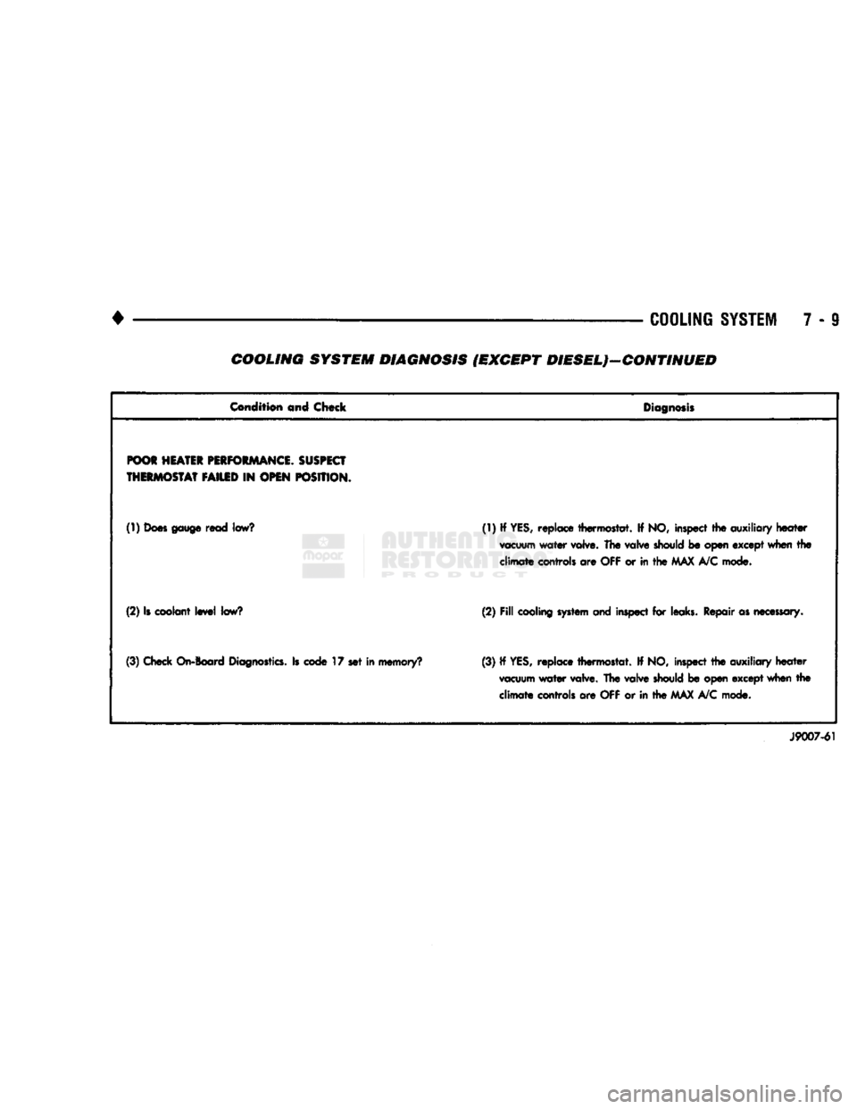
7 - 9 COOLING SYSTEM DIAGNOSIS (EXCEPT DIESEL)—CONTINUED
Condition
and Chock
Diagnosis
POOR
HEATER
PERFORMANCE.
SUSPECT
THERMOSTAT
FAILED
IN
OPEN
POSITION.
(1)
Does gauge
read
low?
(1) If YES, replace thermostat. If NO, inspect the
auxiliary
heater
vacuum
water valve. The
valve
should
be open except when the
climate
controls are
OFF
or in the
MAX
A/C mode.
(2) Is coolant level
low?
(2)
Fill
cooling system and
inspect for leaks. Repair as
necessary.
(3) Check
On-Board
Diagnostics.
Is
code
17 set in memory? (3) If
YES,
replace thermostat. If NO, inspect the auxiliary heater
vacuum
water valve. The valve
should
be open except when the climate controls are OFF or in the MAX A/C mode.
J9007-61
Page 281 of 1502
7-10 COOLING SYSTEM
•
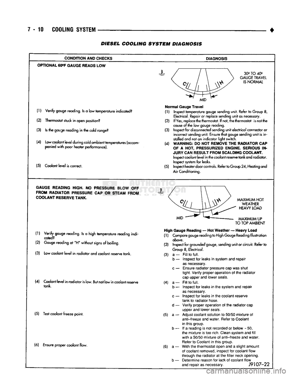
DIESEL
COOLING SYSTEM
DIAGNOSIS
CONDITION AND CHECKS
DIAGNOSIS
OPTIONAL
60»F
GAUGE
READS
LOW 30° TO 40°
GAUGE
TRAVEL
IS
NORMAL
(1)
Verify
gauge reading. Is a low
temperature
indicated?
(2) Thermostat stuck in open position?
(3) Is the gauge reading in the cold range?
(4) Low coolant
level
during cold ambient temperatures (accom panied
with
poor
heater
performance).
(5) Coolant
level
is correct.
MID
Normal
Gauge
Travel
(1) Inspect
temperature
gauge sending unit. Refer to Group 8,
Electrical. Repair or replace sending
unit
as necessary.
(2) If
Yes,
replace the thermostat. If not, the thermostat is not the
cause
of the low gauge
reading.
(3) Inspect for disconnected sending
unit
electrical
connector or
incorrect
sending unit. Ensure
that
gauge sending
unit
is in
stalled and not an indicator light switch.
(4) WARNING: DO NOT REMOVE THE RADIATOR CAP
OF
A HOT, PRESSURIZED ENGINE. SERIOUS IN
JURY CAN RESULT FROM SCALDING COOLANT. Inspect coolant
level
in the coolant reserve tank and radiator. Inspect system for leaks.
(5) Inspect
heater
door
controls.
Refer to Group 24, Heating and
Air Conditioning.
GAUGE
READING HIGH. NO PRESSURE BLOW OFF FROM RADIATOR PRESSURE CAP OR STEAM FROM
COOLANT
RESERVE
TANK.
X
(1)
Verify
gauge reading. Is a high
temperature
reading indi
cated?
(2) Gauge reading at "H"
without
signs
of boiling.
(3) Low coolant
level
in radiator and coolant reserve tank.
MAXIMUM
HOT
WEATHER
HEAVY
LOAD
MAXIMUM
UP
TO
TOP AMBIENT High Gauge
Reading
— Hot
Weather
—
Heavy
Load
(1) Compare gauge reading to High Gauge Reading Illustration
above.
(2) Inspect for grounded
gauge,
sending
unit
or circuit. Refer to
Group
8, Electrical.
(4) Coolant
level
in radiator
is
low.
But
not low in coolant reserve tank.
(5) Test coolant
freeze
point. (3) a-
b — (4) a-
b —
d —
(5) a- (6) Ensure proper coolant flow.
(6) a-
b —
Fill
to
full.
Inspect for leaks in system and
repair
as
necessary.
Ensure
radiator pressure cap was shut
tight.
Verify
proper operation of the radiator
cap
upper and lower
seals.
Fill
to
full.
Inspect for leaks in the system and
repair
as
necessary.
Inspect for leaks in the coolant reserve
tank to radiator hose.
Verify
proper operation of the radiator cap
upper and lower
seals.
Adjust coolant solution to
50/50
mixture
of
anti-freeze
and
water.
Refer to Coolant
in this group. If a reading is not recorded or below - 50.
the
mixture
is too rich. Clean system and
fill
with
a
50/50
mixture
of
anti-freeze
and
water.
Refer to Coolant in this group.
With the thermostat open and a slight amount
of coolant removed, inspect for coolant flow
through the radiator at the
filler
neck opening. Determine reason for lack of coolant flow
and
repair
as necessary.
J9107-22
Page 285 of 1502
7 - 14 COOLING SYSTEM
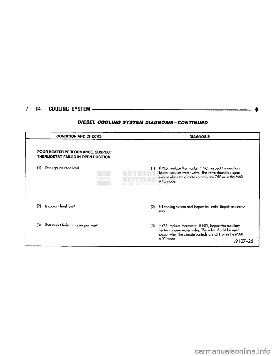
• DIESEL COOLING SYSTEM DIAGNOSIS-CONTINUED
CONDITION
AND
CHECKS
DIAGNOSIS
POOR
HEATER
PERFORMANCE.
SUSPECT
THERMOSTAT
FAILED
IN
OPEN
POSITION.
(1)
Does
gauge
read
low?
(1) If
YES,
replace thermostat. If
NO,
inspect
the auxiliary
heater
vacuum
water
valve.
The valve
should
be open
except
when
the climate
controls
are
OFF
or in the
MAX
A/C
mode.
(2)
Is
coolant
level
low?
(2)
Fill
cooling
system
and
inspect
for
leaks.
Repair
as
neces
sary.
(3) Thermostat failed in open
position?
(3) If
YES,
replace thermostat. If
NO,
inspect
the auxiliary
heater
vacuum
water
valve.
The valve
should
be open
except
when
the climate
controls
are
OFF
or in the
MAX
A/C
mode.
J9107-25