1993 DODGE TRUCK heater
[x] Cancel search: heaterPage 298 of 1502
•
COOLING
SYSTEM
7 - 27 down to -67.7°C (-90°F). A higher percentage will
freeze at a warmer temperature. Also, a higher per centage of antifreeze can cause the engine to over
heat because specific heat of antifreeze is lower than
that of water.
CAUTION:
Richer
antifreeze
mixtures
cannot
be
measured
with
normal
field
equipment
and can
cause
problems
associated
with 100
percent
ethyl
ene-glycol.
COOLANT SELECTION-ADDITIVES The presence of aluminum components in the cool
ing system requires strict corrosion protection. Main
tain coolant at specified level with a mixture of ethylene-glycol based antifreeze and water. Only use an antifreeze containing ALUGARD 340-2
™
such as
Mopar Antifreeze. If coolant becomes contaminated
or looses color, drain and flush cooling system and
fill with correctly mixed solution.
A 0.25 percent emulsifiable oil is added to the ra
diator at the factory to prevent solder corrosion.
CAUTION:
Do not use
coolant
additives
that are
claimed
to
improve
engine
cooling.
COOLANT SERVICE-EXCEPT DIESEL It is recommended that the cooling system be
drained and flushed at 84,000 kilometers (52,500
miles) or 3 years, whichever occurs first. Then every
two years or 48,000 kilometers (30,000 miles), which ever occurs first.
COOLANT SERVICE-DIESEL ENGINE It is recommended that the cooling system be
drained and flushed every 24 months or 38,600 kilo meters (24,000 miles), whichever occurs first.
COOLANT LEVEL CHECK-ROUTINE Do not remove radiator cap for routine coolant
level inspections. The coolant level can be checked at the coolant reserve/overflow tank.
The coolant reserve/overflow system provides a
quick visual method for determining the coolant
level without removing the radiator pressure cap.
With engine idling and at normal operating temper ature, observe coolant level in coolant reserve/over
flow tank. The coolant level should be between the MIN and MAX (diesel engine) or ADD and FULL (gas engines) marks.
ADDING ADDITIONAL COOLANT-ROUTINE Do not remove the radiator cap to add coolant
to the system. When adding coolant to maintain the correct level, do so at the coolant reserve/overflow
tank with a 50/50 mixture of ethylene-glycol anti
freeze (containing Alugard 340-2 ™) and water. Re move the radiator cap only for testing or when
refilling the system after service. Removing cap un necessarily can cause loss of coolant and allow air to
enter system. This produces corrosion.
COOLANT LEVEL CHECK-SERVICE The cooling system is closed and designed to main
tain coolant level to the top of the radiator.
WARNING:
DO
NOT OPEN RADIATOR DRAINCOCK
WITH
ENGINE RUNNING
OR
WHILE ENGINE
IS HOT
AND COOLING
SYSTEM
IS
UNDER
PRESSURE.
When vehicle servicing requires a coolant level
check in the radiator, drain several ounces of coolant
from the radiator drain cock. Do this while observing
the coolant reserve/overflow system tank. The cool ant level in the reserve/overflow tank should drop
slightly. If not, inspect for a leak between radiator and coolant reserve/overflow system connection. Re
move radiator cap. The coolant level should be to the
top of the radiator. If not and if coolant level in re serve/overflow tank is at the ADD (gas engines) or
MIN (5.9L diesel engine) mark, check for:
• An air leak in the coolant reserve/overflow tank
• An air leak in the radiator filler neck
• Leak in the pressure cap seal to the radiator filler
neck
LOW COOLANT LEVEL-AERATION If the coolant level in the radiator drops below the
top of the radiator core tubes, air will enter the sys
tem. Low coolant level can cause the thermostat pellet
to be suspended in air instead of coolant. This will cause the thermostat to open later, which in turn causes higher coolant temperature. Air trapped in
cooling system also reduces the amount of coolant
circulating in the heater core. This may result in low
heat output.
DEAERATION As the engine operates, air trapped in the cooling
system gathers under the radiator cap. The next time
engine is operated, thermal expansion of coolant will
push trapped air past radiator cap into coolant re serve/overflow tank. Here it escapes to atmosphere in
the tank. When engine cools down the coolant, it will
be drawn from reserve/overflow tank into radiator to replace removed air.
DRAINING
COOLING
SYSTEM
WARNING:
DO NOT
REMOVE
THE
CYLINDER BLOCK DRAIN PLUGS
OR
LOOSEN THE RADIATOR
DRAIN PLUG
WITH
SYSTEM
HOT AND
UNDER
PRESSURE.
SERIOUS BURNS
FROM
COOLANT
CAN OCCUR.
Page 299 of 1502
7 - 28
COOLING SYSTEM
DO NOT WASTE reusable coolant. If the solution
is clean, drain the coolant into a clean container for
reuse.
(1) Start the engine and place the heater control
temperature selector in the Full On position. Engine vacuum is needed to actuate the heater controls.
(2) Turn the ignition off. (3) Do not remove radiator cap when draining cool
ant from reserve/overflow tank. Open radiator drain
plug and when tank is empty, remove radiator cap. If
the coolant reserve/overflow tank does not drain, re fer to the Testing Cooling System for Leaks section
in this group. The coolant need not be removed from
tank unless the system is being refilled with fresh mixture.
(4) On vehicles equipped with gas powered en
gines,
remove the cylinder block drain plugs. These are located on the sides of the block towards the
front of engine, just above the oil pan (Fig. 36).
Fig.
36 Drain Plugs—Gas Powered
Engines—Typical
(5) Remove radiator pressure cap.
REFILLING
THE
COOLING SYSTEM
Clean cooling system prior to refilling. Refer to
Cooling System Cleaning section of this group. (1) Install the cylinder block drain plugs (Fig. 36).
(2)
Close radiator drain plug.
(3) Fill the cooling system with a 50/50 mixture of
water and antifreeze. (4) Fill coolant reserve/overflow tank to the MAX
(5.9L diesel engine) or FULL (gas engines) mark. (5) Start and operate engine until thermostat
opens. Upper radiator hose should be warm to touch. (6) If necessary, add 50/50 water and antifreeze
mixture to the coolant reserve/overflow tank to main
tain coolant level. This level should be between the MAX and MIN (5.9L diesel engine) or ADD and FULL (gas engines) marks. The level in the reserve/ overflow tank may drop below the MIN (or ADD)
mark after three or four warm-up and cool-down cy
cles.
COOLING SYSTEM CLEANING/REVERSE FLUSHING
CLEMMING Drain cooling system and refill with water. Run
engine with radiator cap installed until upper radia
tor hose is hot. Stop engine and drain water from system. If water is dirty, fill system with water, run
engine and drain system. Repeat until water drains
clean.
REVERSE
FLUSHING
Reverse flushing of cooling system is the forcing of
water through the cooling system. This is done using air pressure in the opposite direction of normal cool
ant flow. It is usually only necessary with very dirty
systems with evidence of partial plugging.
REVERSE
FLUSHING
RADIATOR Disconnect radiator hoses from radiator inlet and
outlet. Attach a section of radiator hose to radiator
bottom outlet fitting and insert flushing gun. Con
nect a water supply hose and air supply hose to flushing gun.
CAUTION:
Internal
radiator
pressure must
not'ex
ceed 138 kPa (20 psi) as damage to
radiator
may re
sult
Allow radiator to fill with water. When radiator is
filled, apply air in short blasts. Allow radiator to re
fill between blasts. Continue this reverse flushing
until clean water flows out through rear of radiator cooling tube passages. Have radiator cleaned more extensively by a radiator repair shop.
REVERSE
FLUSHING
ENGINE-EXCEPT DIESEL Drain cooling system. Remove thermostat housing
and thermostat. Install thermostat housing. Discon
nect radiator upper hose from radiator and attach
flushing gun to hose. Disconnect radiator lower hose
from water pump and attach a lead-away hose to wa
ter pump inlet fitting.
CAUTION;
On vehicles equipped
with
a
heater
water
control
valve, be sure
heater
control
valve is closed
(heat
off). This
will
prevent
coolant
flow
with
scale
and
other
deposits
from
entering
heater
core.
Connect water supply hose and air supply hose to
flushing gun. Allow engine to fill with water. When engine is filled, apply air in short blasts, allowing system to fill between air blasts. Continue until
clean water flows through the lead away hose.
Page 300 of 1502
+
Fig.
37
Reverse-flushing—5.9L
Diesel
(5) Attach water supply hose to heater tube.
(6) Back-flush the engine until clean water exits
the water pump inlet.
CHEMICAL
CLEANING
In some instances, use a radiator cleaner (Mopar
Radiator Kleen or equivalent) before flushing. This
will soften scale and other deposits and aid flushing operation.
CAUTION;
Follow manufacturers instructions when
using
these
products.
TESTING
COOLING
SYSTEM
FOR
LEAKS
ULTRAVIOLET
LIGHT
METHOD
A leak detection additive is available through the
parts department that can be Sidfled to cooling sys
tem. The additive is highly visible under ultraviolet
COOLING
SYSTEM
7 - 29
Fig.
38
Leak
Detection
Using
Black
Light—Typical
PRESSURE
TESTER
METHOD
The engine should be at normal operating temper
ature. Recheck the system cold if cause of coolant
loss is not located during the warm engine examina
tion.
WARNING:
HOT,
PRESSURIZED
COOLANT
CAN
CAUSE
INJURY
BY
SCALDING.
Carefully remove radiator pressure cap from filler
neck and check coolant level. Push down on cap to
disengage it from stop tabs. Wipe inside of filler neck and examine lower inside sealing seat for nicks,
cracks, paint, dirt and solder residue. Inspect radia
tor-to-reserve/overflow tank hose for internal obstruc
tions.
Insert a wire through the hose to be sure it is
not obstructed.
Inspect cams on outside of filler neck. If cams are
bent, seating of pressure cap valve and tester seal
will be affected. Bent cams can be reformed if done carefully. Attach pressure tester (7700 or an equivalent) to radiator filler neck (Fig. 39).
Operate tester pump to apply 103.4 kPa (15 psi)
pressure to system. If hoses enlarge excessively or
Remove lead away hose, flushing gun, water sup
ply hose and air supply hose. Remove thermostat housing and install thermostat. Install thermostat
housing with a replacement gasket. Refer to Thermo stat Replacement. Connect radiator hoses. Refill cool
ing system with correct antifreeze/water mixture.
Refer to Refilling the Cooling System.
REVERSE
FLUSHING
ENGINE-DIESEL
(1) Drain the cooling system. (2) Disconnect the upper hose from the radiator.
(3) Disconnect the radiator lower hose from the
water pump.
CAUTION;
Be
sure
the
heater
control valve is
closed
(heat
off).
This
will
prevent coolant flow
with
scale
and other
deposits
from entering the
heater
core.
(4) Remove the heater core inlet hose from tube
(Fig. 37). light (black light). Pour one ounce of additive into
cooling system. Place heater control unit in HEAT
position. Start and operate engine until radiator up
per hose is warm to touch. Aim black light (tool C-4555 or an equivalent) at components to be
checked. If leaks are present, black light will cause additive to glow a bright green color.
The black light can be used in conjunction with a
pressure tester to determine if any external leaks ex ist (Fig. 38).
Page 301 of 1502

7 - 30
COOLING
SYSTEM
•
COOLING
SYSTEM
Fig.
39
Pressure
Testing
Cooling
System—Typical bulges while testing, replace as necessary. Observe
gauge pointer and determine condition of cooling sys
tem according to following criteria:
Holds Steady: If pointer remains steady for two
minutes, serious coolant leaks are not present in sys
tem. However, there could be an internal leak that does not appear with normal system test pressure. If
it is certain that coolant is being lost and leaks can
not be detected, inspect for interior leakage or per
form Internal Leakage Test.
Drops Slowly: Indicates a small leak or seepage is
occurring. Examine all connections for seepage or
slight leakage with a flashlight. Inspect radiator,
hoses,
gasket edges and heater. Seal small leak holes
with a Sealer Lubricant (or equivalent). Repair leak
holes and inspect system again with pressure ap
plied.
Drops Quickly: Indicates that serious leakage is
occurring. Examine system for external leakage. If
leaks are not visible, inspect for internal leakage.
Large radiator leak holes should be repaired by a
reputable radiator repair shop.
INTERNAL LEAKAGE INSPECTION Remove engine oil pan drain plug and drain a
small amount of engine oil. If coolant is present in
the pan, it will drain first because it is heavier than
oil.
An alternative method is to operate engine for a
short period to churn the oil. After this is done, re
move engine dipstick and inspect for water globules.
Also inspect transmission dipstick for water globules and transmission fluid cooler for leakage.
WARNING:
WITH
PRESSURE TESTER TOOL
7700
INSTALLED
ON
RADIATOR,
DO
NOT ALLOW
PRES
SURE
TO
EXCEED
110 KPA (20
PSI). PRESSURE
WILL
BUILD
UP
QUICKLY
IF A
COMBUSTION LEAK
IS
PRESENT.
TO
RELEASE
PRESSURE,
ROCK
TESTER
FROM SIDE
TO
SIDE. WHEN REMOVING
TESTER,
DO NOT
TURN TESTER MORE THAN
1/2
TURN
IF
SYSTEM
IS
UNDER
PRESSURE.
Operate engine without pressure cap on radiator
until thermostat opens. Attach a Pressure Tester to
filler neck. If pressure builds up quickly it indicates a combustion leak exists. This is usually the result of
a cylinder head gasket leak or crack in engine. Re
pair as necessary.
If there is not an immediate pressure increase,
pump the Pressure Tester. Do this until indicated
pressure is within system range of 110 kPa (16 psi). Fluctuation of gauge pointer indicates compression or
combustion leakage into cooling system.
Because the vehicle is equipped with a catalytic
converter, do not remove spark plug cables or short
out cylinders (non-diesel engines) to isolate compres
sion leak.
If the needle on dial of pressure tester does not
fluctuate, race engine a few times to check for an ab normal amount of coolant or steam. This would be
emitting from exhaust pipe. Coolant or steam from
exhaust pipe may indicate a faulty cylinder head
gasket, cracked engine cylinder block or cylinder
head. A convenient check for exhaust gas leakage into
cooling system is provided by a commercially avail able Block Leak Check tool. Follow manufacturers
instructions when using this product.
COMBUSTION LEAKAGE TEST-WITHOUT
PRESSURE TESTER DO NOT WASTE reusable coolant. If solution is
clean, drain coolant into a clean container for reuse.
WARNING:
DO NOT
REMOVE CYLINDER BLOCK DRAIN PLUGS
OR
LOOSEN RADIATOR DRAIN-
COCK
WITH
SYSTEM
HOT AND
UNDER PRES
SURE.
SERIOUS BURNS FROM COOLANT
CAN
OCCUR.
Drain sufficient coolant to allow thermostat re
moval. Refer to Thermostat Replacement. Disconnect
water pump drive belt. Add coolant to radiator to bring level to within 6.3
mm (1/4 in) of top of thermostat housing.
CAUTION:
Avoid
overheating.
Do not
operate
en
gine
for an
excessive
period
of
time.
Open
drain-
cock
immediately
after
test
to
eliminate
boil
over.
Start engine and accelerate rapidly three times, to
approximately 3000 rpm while observing coolant. If
internal engine combustion gases% are leaking into
cooling system, bubbles will appear in coolant. If
bubbles do not appear, internal combustion gas leak age is not present.
COOLANT
RESERVE/0WERFL0W
SYSTEM
The coolant reserve/overflow system (Fig. 40 or 41)
works in conjunction with the radiator pressure cap.
Page 304 of 1502
•
COOLING
SYSTEM
7 - 33 The radiator supplies sufficient heat transfer to
cool the engine and automatic transmission (if equipped).
RADIATOR COOLANT FLOW CHECK
Use the following procedure to determine if coolant
is flowing through the cooling system.
(1) Idle engine until operating temperature is
reached. If the upper radiator hose is warm to the
touch, the thermostat is opening and coolant is flow ing to the radiator.
WARNING:
HOT,
PRESSURIZED COOLANT
CAN
CAUSE
INJURY
BY
SCALDING. USING
A
RAG
TO
COVER
THE
RADIATOR
PRESSURE
CAP,
OPEN RADIATOR
CAP
SLOWLY
TO THE
FIRST STOP.
THIS
WILL
ALLOW
ANY
BUILT-UP
PRESSURE
TO
VENT
TO
THE
RESERVE/OVERFLOW TANK. AFTER
PRESSURE
BUILD-UP
HAS
BEEN RELEASED,
RE
MOVE
CAP
FROM FILLER NECK.
(2) Drain a small amount of coolant from the radi
ator until the ends of the radiator tubes are visible
through the filler neck. Idle the engine at normal op
erating temperature. If coolant is flowing past the
exposed tubes, the coolant is circulating.
RADIATOR REMOVAL-EXCEPT DIESEL
(1) Disconnect negative battery cable from battery.
WARNING;
DO NOT
REMOVE
THE
CYLINDER BLOCK DRAIN PLUGS
OR
LOOSEN
THE
RADIATOR
DRAINCOCK
WITH
THE
SYSTEM
HOT AND
UNDER
PRESSURE.
SERIOUS BURNS FROM COOLANT
CAN OCCUR.
(2) Drain the cooling system. Refer to Draining
Cooling System.
(3) Disconnect throttle cable from clip at radiator
fan shroud. (4) Remove hose clamps and hoses from radiator.
Special Clamp Tool number 6094 (Fig. 44) may be
used to remove the constant tension clamps.
(5) Remove coolant reserve/overflow tank hose
from radiator filler neck nipple.
(6) If equipped with an automatic transmission
(except diesel), disconnect oil cooler hoses at radiator
lower tank.
(7) Remove fan shroud mounting bolts/clips and
position shroud rearward on engine (Fig. 45). (8) Loosen radiator lower mounting bolts. Remove
the upper mounting bolts. Lift radiator straight up and out of engine compartment. Take care not to
damage radiator cooling fins or tubes.
INSTALLATION
(1) Position shroud rearward on engine.
(2) Slide radiator into position. Place behind radi
ator support with lower mounting holes (slots) rest-
HOSE
CLAMP
TOOL
6094
HOSE
CLAMP
J9207-36
Fig.
44
Hose
Clamp
Tool
RADIATOR SHROUD
MOUNTING MOUNTING
BOLTS
CUPS
RADIATOR
V1
FAN SHROUD^
J9207-44
Fig.
45 Radiator and Fan
Shroud—Gas Engines
ing on loosened bottom mounting bolts. Install upper
mounting bolts. Tighten all mounting bolts to 11
N*m (95 in. lbs.) torque.
(3) Connect radiator hoses.
(4) Connect transmission oil cooler lines to bottom
tank. Tighten hose clamps to 4 N#m (35 in. lbs.)
torque.
(5) Position fan shroud on radiator flange. Install
mounting clips (Fig. 45).
(6) Connect throttle cable to fan shroud.
(7) Position heater controls to full heat position.
(8) Fill cooling system with coolant. Refer to Refill
ing Cooling System in this group.
(9) Operate engine until it reaches normal temper
ature. Check cooling system and automatic transmis
sion (if equipped) fluid levels.
RADIATOR REMOVAL-DIESEL
(1) Disconnect negative battery cable from battery.
Page 305 of 1502
7 - 34
COOLING SYSTEM
•
WARNING;
DO NOT
REMOVE
THE
CYLINDER
BLOCK DRAIN PLUGS
OR
LOOSEN
THE
RADIATOR
DRAINCOCK
WITH
THE
SYSTEM
HOT AND
UNDER
PRESSURE.
SERIOUS BURNS FROM COOLANT
CAN OCCUR.
(2) Drain the cooling system. Refer to Draining
Cooling System in this group. (3) Remove hose clamps and hoses from radiator.
Remove coolant reserve/overflow tank hose from ra diator filler neck nipple.
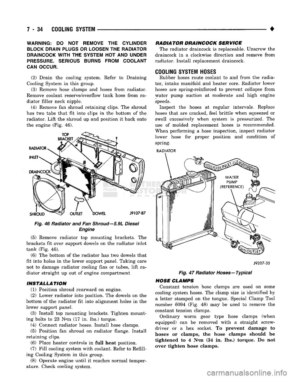
(4) Remove fan shroud retaining clips. The shroud
has two tabs that fit into clips in the bottom of the radiator. Lift the shroud up and position it back onto
the engine (Fig. 46).
Fig. 46 Radiator and Fan
Shroud—5.9L
Diesel Engine
(5) Remove radiator top mounting brackets. The
brackets fit over support dowels on the radiator inlet
tank (Fig. 46).
(6) The bottom of the radiator has two dowels that
fit into holes in the lower support panel. Taking care not to damage radiator cooling fins or tubes, lift ra
diator straight up out of engine compartment
INSTALLATION (1) Position shroud rearward on engine.
(2) Lower radiator into position. The dowels on the
bottom of the radiator fit into alignment holes in the lower support panel.
(3) Install top mounting brackets. Tighten mount
ing bolts to 23 N*m (17 in. lbs.) torque. (4) Connect radiator hoses. Install hose clamps.
(5) Position fan shroud on radiator flange. Install
retaining clips. (6) Place heater controls in full heat position.
(7) Fill cooling system with coolant. Refer to Refill
ing Cooling System in this group.
(8) Operate engine until it reaches normal temper
ature. Check cooling system. RADIATOR DRAINCOCK SERVICE
The radiator draincock is replaceable. Unscrew the
draincock in a clockwise direction and remove from
radiator. Install replacement draincock.
COOLING SYSTEM HOSES
Rubber hoses route coolant to and from the radia
tor, intake manifold and heater core. Radiator lower
hoses are spring-reinforced to prevent collapse from
water pump suction at moderate and high engine speeds. Inspect the hoses at regular intervals. Replace
hoses that are cracked, feel brittle when squeezed or swell excessively when system is pressurized. The
use of molded replacement hoses is recommended.
When performing a hose inspection, inspect radiator lower hose for proper position and condition of spring.
RADIATOR
J9207-35
Fig. 47 Radiator Hoses—Typical
HOSE CLAMPS Constant tension hose clamps are used on some
cooling system hoses. The clamp size is identified by a letter stamped on the tongue. Special Clamp Tool
number 6094 (Fig. 48) may be used to remove the
constant tension clamps.
Ordinary worm gear type hose clamps (when
equipped) can be removed with a straight screw
driver or a hex socket. To prevent damage to
hoses or clamps, the hose clamps should be
tightened to 4 N«m (34 in. lbs.) torque. Do not
over tighten hose clamps.
Page 319 of 1502
7
- 48
COOLING
SYSTEM
•
ENGINE BLOCK HEATERS
GENERAL
INFORMATION
DESCRIPTION AND OPERATION An optional engine block heater
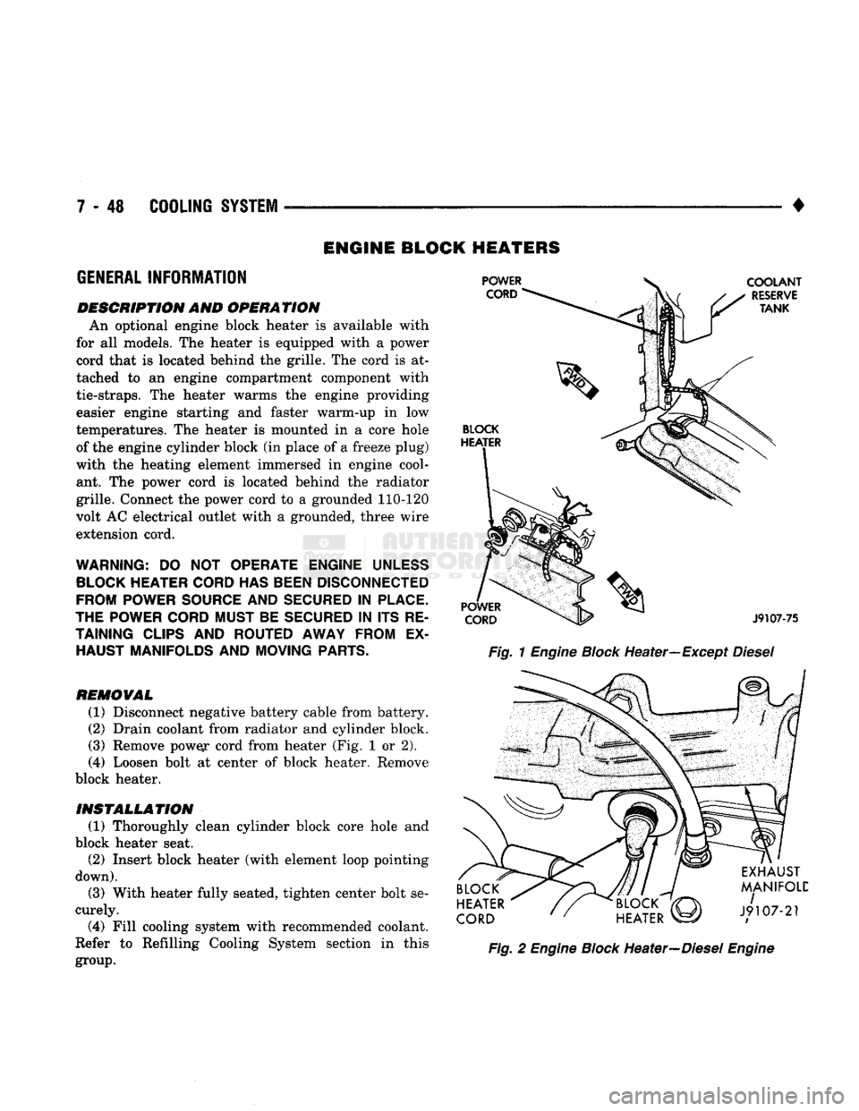
is
available with
for
all
models. The heater
is
equipped with
a
power
cord that
is
located behind the grille. The cord
is at
tached
to an
engine compartment component with
tie-straps.
The
heater warms
the
engine providing easier engine starting
and
faster warm-up
in low
temperatures. The heater
is
mounted
in a
core hole of the engine cylinder block (in place of
a
freeze plug)
with
the
heating element immersed
in
engine cool ant.
The
power cord
is
located behind
the
radiator
grille. Connect the power cord
to a
grounded 110-120
volt AC electrical outlet with
a
grounded, three wire
extension cord.
WARNING:
DO NOT
OPERATE ENGINE
UNLESS
BLOCK
HEATER
CORD
HAS
BEEN
DISCONNECTED
FROM POWER
SOURCE
AND
SECURED
IN
PLACE.
THE POWER
CORD
MUST BE
SECURED
IN ITS RE
TAINING
CLIPS
AND ROUTED AWAY FROM
EX
HAUST MANIFOLDS AND MOVING
PARTS.
REMOVAL
(1) Disconnect negative battery cable from battery.
(2) Drain coolant from radiator and cylinder block.
(3) Remove pow^r cord from heater (Fig.
1 or 2).
(4)
Loosen bolt
at
center
of
block heater. Remove
block heater.
INSTALLATION (1) Thoroughly clean cylinder block core hole
and
block heater seat. (2) Insert block heater (with element loop pointing
down).
(3) With heater fully seated, tighten center bolt se
curely.
(4)
Fill cooling system with recommended coolant.
Refer
to
Refilling Cooling System section
in
this
group.
Fig.
1
Engine
Block
Heater—Except
Diesel
Fig.
2
Engine
Block
Heater—Diesel
Engine
Page 384 of 1502
•
INSTRUMENT PANEL
AND
GAUGES
8E - 3
MALFUNCTION INDICATOR (CHECK ENGINE)
Fig.
5
Distance Sensor
If
the
input from
one of the
following sensors fails
an internal Powertrain Control Module
(PCM)
self
check,
the PCM
turns
on the
Check Engine Lamp. The
PCM
then substitutes
a
modified signal
in
place
of
the one
that failed until
a
repair
is
made:
• Manifold Absolute Pressure (MAP) Sensor
• Throttle Position Sensor
• Coolant Temperature Sensor
• Battery Voltage Sense
• Battery Voltage
Too
High
Refer
to the
appropriate Powertrain Diagnostic
Test Procedures manual
for
further information.
ELECTRONIC DIGITAL CLOCK
The electronic digital clock
is in the
radio.
The
clock
and
radio each
use the
display panel built into
the radio.
A
digital readout indicates
the
time
in
hours
and
minutes whenever
the
ignition switch
is in
the
ON or ACC
position. When
the
ignition switch
is in the OFF
position
or
when
the
radio frequency
is
being displayed, time keeping
is
accurately maintained. The procedure
for
setting
the
clock varies slightly
with each radio.
The
correct procedure
is
described under
the
individual radio operating instructions
re
ferred
to in the
Owner Manual supplied with
the ve
hicle.
MESSAGE CENTER—GAS ENGINE
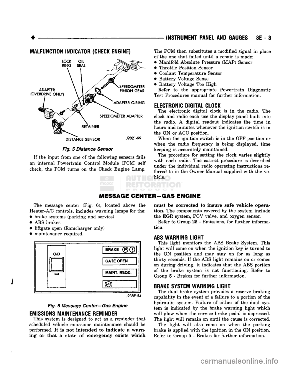
The message center
(Fig. 6),
located above
the
Heater-A/C controls, includes warning lamps
for the:
• brake systems (parking
and
service)
•
ABS
brakes • liftgate open (Ramcharger only)
• maintenance required.
O/D
BRAKE
(P)(7
GATE OPEN
MAINT
REQD.
J938E-54
Fig.
6
Message Center—Gas Engine
EMISSIONS
MAINTENANCE REMINDER
This system
is
designed
to act as a
reminder that
scheduled vehicle emissions maintenance should
be
performed.
It is not
intended
to
indicate
a
warn
ing
or
that
a
state
of
emergency exists which must
be
corrected
to
insure safe vehicle opera
tion.
The
components covered
by the
system include
the
EGR
system,
PCV
valve,
and
oxygen sensor. Refer
to
Group
25 -
Emissions,
for
further informa
tion.
ABS
WARNING
LIGHT
This light monitors
the ABS
Brake System. This
light will come
on
when
the
ignition
key is
turned
to
the
ON
position
and may
stay
on for as
long
as
thirty seconds.
If the ABS
light remains
on or
comes on during driving,
it
indicates that
the ABS
portion
of
the
brake system
is not
functioning. Refer
to
Group
5 -
Brakes
for
further information.
BRAKE
SYSTEM WARNING
LIGHT
The dual brake system provides
a
reserve braking
capability
in the
event
of a
failure
to a
portion
of the
hydraulic system. Failure
of
either
of the
dual sys
tem
is
indicated
by the
brake warning light which
will glow when
the
service brake pedal
is
depressed.
The light will remain
on
until
the
cause
is
corrected. The light will also come
on
when
the
parking
brake
is
applied with
the
ignition
in the ON
position.
Refer
to
Group
5 -
Brakes
for
further information.