1993 DODGE TRUCK AUX
[x] Cancel search: AUXPage 133 of 1502
3
- 4
REAR SUSPENSION
AND
AXLE
•
SHOCK
ABSORBER
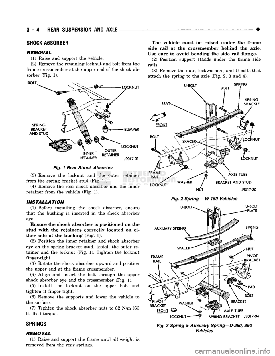
REMOVAL (1) Raise and support the vehicle.
(2) Remove the retaining locknut and bolt from the
frame crossmember at the upper end of the shock ab sorber (Fig. 1). BOLT
SPRING
BRACKET
AND STUD LOCKNUT
BUMPER LOCKNUT
OUTER
INNER RETAINER
RETAINER
J90T7-31
Fig.
1 Rear
Shock
Absorber
(3) Remove the locknut and the outer retainer
from the spring bracket stud (Fig. 1).
(4) Remove the rear shock absorber and the inner
retainer from the vehicle (Fig. 1).
INSTALLATION (1) Before installing the shock absorber, ensure
that the bushing is inserted in the shock absorber
eye.
Ensure the shock absorber is positioned on the
stud with the retainers correctly located on ei
ther side of the bushing (Fig. 1).
(2) Position the inner retainer and shock absorber
eye on the spring bracket stud. Install the outer re
tainer and the locknut (Fig. 1). Tighten the locknut finger-tight.
(3) Rotate the shock absorber upward and position
the upper end at the frame crossmember.
(4) Align and insert the bolt through the upper
shock absorber eye and the crossmember (Fig. 1).
(5) Install the locknut on the upper bolt and
tighten it finger-tight.
(6) Remove the supports and lower the vehicle to
the surface. (7) Tighten the shock absorber nuts to 82 N*m (60
ft. lbs.) torque.
SPRINGS
REMOVAL (1) Raise and support the frame until all weight is
removed from the rear springs. The vehicle must be raised under the frame
side rail at the crossmember behind the axle.
Use care to avoid bending the side rail flange.
(2) Position support stands under the frame side
rails.
(3) Remove the nuts, lockwashers, and U-bolts that
attach the spring to the axle (Fig. 2, 3 and 4).
U-BOLT
SPRING
SPRING
SHACKLE
FRAME
RAIL
LOCKNUT LOCKNUT
LOCKNUT AXLE TUBE
BRACKET
AND
STUD
NUT
J9017-3Q
Fig.
2
Spring—
W-150 Vehicles
U-BOLT^
U-BOLT
~ '
PLATE
IB*
AUXILIARY SPRING
SPRING
FRAME
RAIL
PIVOT
BRACKET
^ . , _
BOLT
'PIVOT'
WA^HFP
^
in^gJ
\
BRACKET
BRACKET WASHER
^
FRONT
C3>
>>JL
^ T^1
AXLE TUBE
LOCKNUT
——Hr
SPRING BRACKET
J9017-34
Fig.
3
Spring
& Auxiliary
Spring—D-250,
350
Vehicles
Page 134 of 1502
•
Fig.
4
Spring
& Auxiliary Spring—W-250, 350
Vehicles
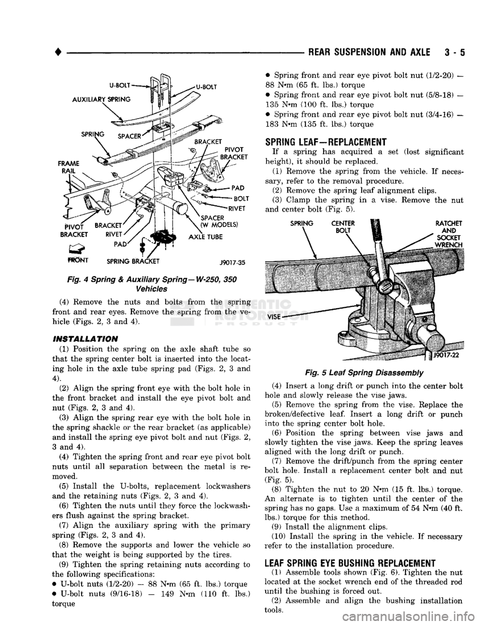
(4) Remove the nuts and bolts from the spring
front and rear eyes. Remove the spring from the ve
hicle (Figs. 2, 3 and 4).
INSTALLATION (1) Position the spring on the axle shaft tube so
that the spring center bolt is inserted into the locat ing hole in the axle tube spring pad (Figs. 2, 3 and
4).
(2) Align the spring front eye with the bolt hole in
the front bracket and install the eye pivot bolt and nut (Figs. 2, 3 and 4). (3) Align the spring rear eye with the bolt hole in
the spring shackle or the rear bracket (as applicable) and install the spring eye pivot bolt and nut (Figs. 2,
3 and 4).
(4) Tighten the spring front and rear eye pivot bolt
nuts until all separation between the metal is re
moved.
(5) Install the U-bolts, replacement lockwashers
and the retaining nuts (Figs. 2, 3 and 4). (6) Tighten the nuts until they force the lockwash
ers flush against the spring bracket. (7) Align the auxiliary spring with the primary
spring (Figs. 2, 3 and 4).
(8) Remove the supports and lower the vehicle so
that the weight is being supported by the tires.
(9) Tighten the spring retaining nuts according to
the following specifications:
• U-bolt nuts (1/2-20) - 88 N*m (65 ft. lbs.) torque
# U-bolt nuts (9/16-18) - 149 N-m (110 ft. lbs.)
torque —
REAR SUSPENSION
AND
AXLE
3 • 5
Fig.
5 Leaf
Spring
Disassembly
(4) Insert a long drift or punch into the center bolt
hole and slowly release the vise jaws.
(5) Remove the spring from the vise. Replace the
broken/defective
leaf.
Insert a long drift or punch into the spring center bolt hole.
(6) Position the spring between vise jaws and
slowly tighten the vise jaws. Keep the spring leaves
aligned with the long drift or punch.
(7) Remove the drift/punch from the spring center
bolt hole. Install a replacement center bolt and nut (Fig. 5).
(8) Tighten the nut to 20 N-m (15 ft. lbs.) torque.
An alternate is to tighten until the center of the spring has no gaps. Use a maximum of 54 N*m (40 ft.
lbs.) torque for this method.
(9) Install the alignment clips.
(10) Install the spring in the vehicle. If necessary
refer to the installation procedure.
LEAF SPRING EYE BUSHING REPLACEMENT
(1) Assemble tools shown (Fig. 6). Tighten the nut
located at the socket wrench end of the threaded rod
until the bushing is forced out. (2) Assemble and align the bushing installation
tools.
• Spring front and rear eye pivot bolt nut (1/2-20) —
88 N«m (65 ft. lbs.) torque
© Spring front and rear eye pivot bolt nut (5/8-18) — 135 N»m (100 ft. lbs.) torque
• Spring front and rear eye pivot bolt nut (3/4-16) — 183 N-m (135 ft. lbs.) torque
SPRING
LEAF—REPLACEMENT
If a spring has acquired a set (lost significant
height), it should be replaced. (1) Remove the spring from the vehicle. If neces
sary, refer to the removal procedure. (2) Remove the spring leaf alignment clips.
(3) Clamp the spring in a vise. Remove the nut
and center bolt (Fig. 5).
Page 186 of 1502
REAR
SUSPENSION
AND
AXLE
3 - 59
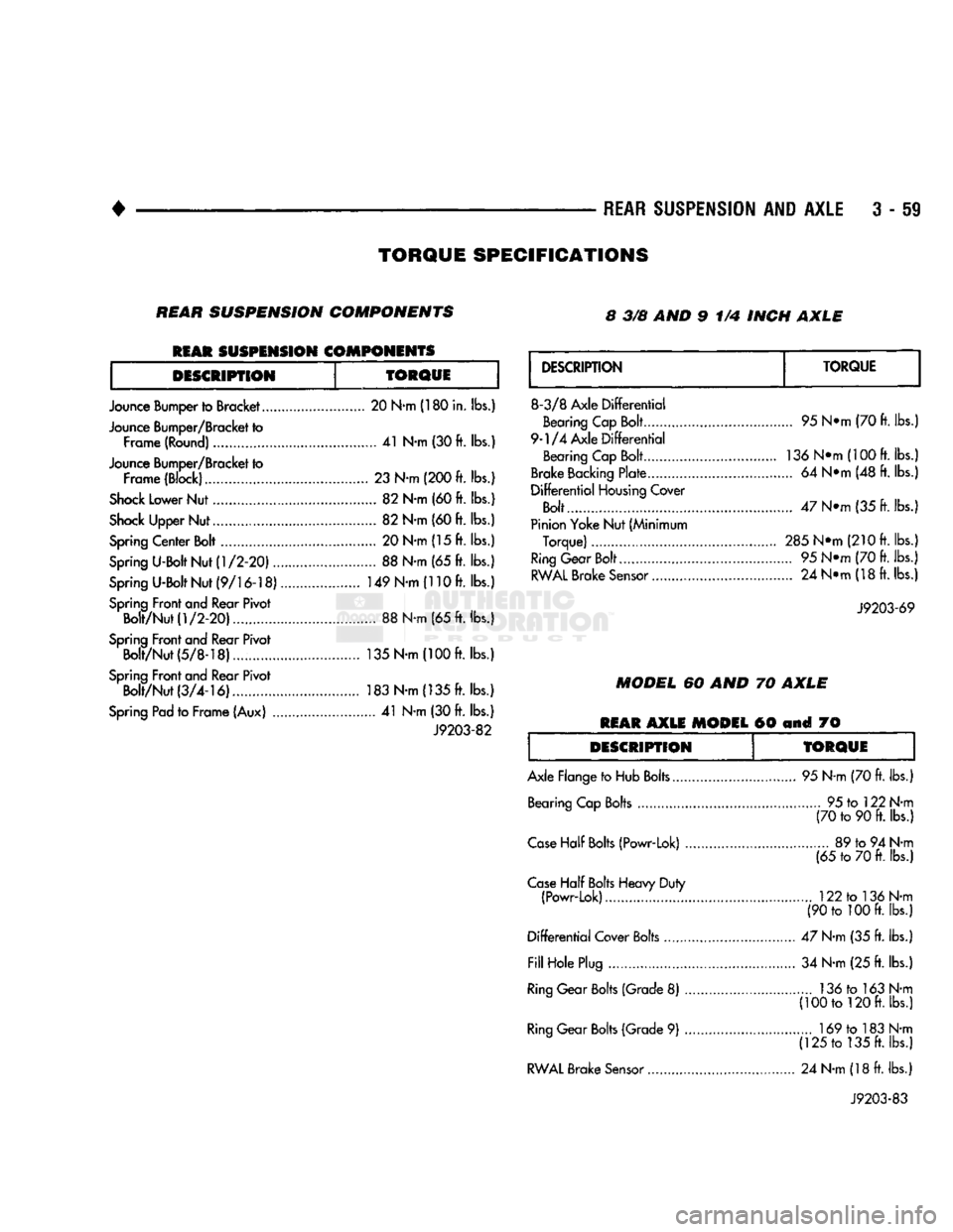
TORQUE
SPECIFICATIONS
REAR
SUSPENSION
COMPONENTS 8 3/8 AND 9 1/4 INCH
AXLE
REAR
SUSPENSION
COMPONENTS
DESCRIPTION
TORQUE
Jounce Bumper to Bracket 20 N-m (180 in. lbs.)
Jounce Bumper/Bracket to Frame (Round) 41 N-m (30 ft. lbs.)
Jounce Bumper/Bracket to Frame (Block)......... 23 N-m (200 ft. lbs.)
Shock
Lower Nut 82 N-m (60 ft. lbs.)
Shock
Upper Nut 82 N-m (60 ft. lbs.)
Spring
Center Bolt 20 N-m (15 ft. lbs.)
Spring
U-Bolt Nut
(1/2-20)
88 N-m (65 ft. lbs.)
Spring
U-Bolt Nut
(9/16-18)
149 N-m (110 ft. lbs.)
Spring
Front and Rear Pivot Bolt/Nut
(1/2-20)
88 N-m (65 ft. lbs.)
Spring
Front and Rear Pivot Bolt/Nut(5/8-18).... 135 N-m
(100ft.
lbs.)
Spring
Front and Rear Pivot Bolt/Nut
(3/4-16)
183 N-m (135 ft. lbs.)
Spring
Pad to Frame (Aux) 41 N-m (30 ft. lbs.)
J9203-82
DESCRIPTION
TORQUE
8-3/8 Axle
Differential
Bearing Cap Bolt
9-1/4 Axle
Differential
Bearing Cap Bolt
Brake
Backing
Plate ,
Differential
Housing
Cover
Bolt
Pinion Yoke Nut (Minimum Torque)
Ring
Gear Bolt...
RWAL
Brake
Sensor
95 N*m (70 ft. lbs.)
136
N*m(100
ft. lbs.)
... 64 N*m (48 ft. lbs.)
47 N*m (35 ft. lbs.;
285Ntti
(210 ft. lbs.)
... 95 N*m (70 ft. lbs.) ... 24 N*m (18 ft. lbs.)
J9203-69
MODEL
60 AND 70
AXLE
REAR
AXLE
MODEL
60 and 70
DESCRIPTION
TORQUE
Axle Flange to Hub Bolts. Bearing Cap Bolts 95 N-m (70 ft. lbs.)
... 95 to 122 N-m (70 to 90 ft. lbs.)
Case
Half
Bolts
(Powr-Lok) ..
Case
Half
Bolts
Heavy Duty (Powr-Lok)
Differential
Cover Bolts
Fill
Hole Plug
Ring
Gear
Bolts
(Grade 8)
Ring
Gear
Bolts
(Grade 9)
RWAL
Brake
Sensor
89 to 94 N-m
(65 to 70 ft. lbs.)
122 to 136 N-m
(90 to 100 ft. lbs.)
47 N-m (35 ft. lbs.) 34 N-m (25 ft. lbs.) 136 to 163 N-m
(100 to 120 ft. lbs.) 169 to 183 N-m
(125 to 135 ft. lbs.)
24 N-m (18 ft. lbs.)
J9203-83
Page 280 of 1502
•
COOLING
SYSTEM
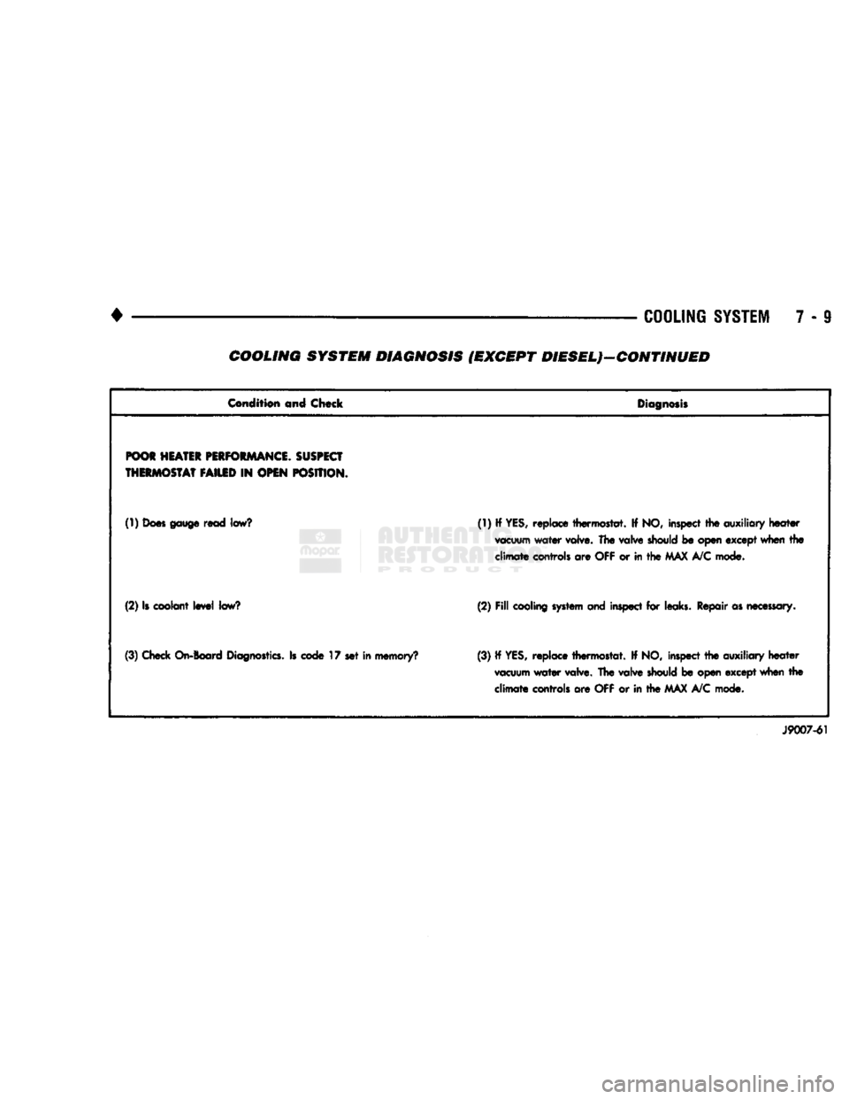
7 - 9 COOLING SYSTEM DIAGNOSIS (EXCEPT DIESEL)—CONTINUED
Condition
and Chock
Diagnosis
POOR
HEATER
PERFORMANCE.
SUSPECT
THERMOSTAT
FAILED
IN
OPEN
POSITION.
(1)
Does gauge
read
low?
(1) If YES, replace thermostat. If NO, inspect the
auxiliary
heater
vacuum
water valve. The
valve
should
be open except when the
climate
controls are
OFF
or in the
MAX
A/C mode.
(2) Is coolant level
low?
(2)
Fill
cooling system and
inspect for leaks. Repair as
necessary.
(3) Check
On-Board
Diagnostics.
Is
code
17 set in memory? (3) If
YES,
replace thermostat. If NO, inspect the auxiliary heater
vacuum
water valve. The valve
should
be open except when the climate controls are OFF or in the MAX A/C mode.
J9007-61
Page 285 of 1502
7 - 14 COOLING SYSTEM
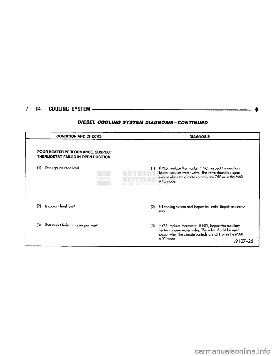
• DIESEL COOLING SYSTEM DIAGNOSIS-CONTINUED
CONDITION
AND
CHECKS
DIAGNOSIS
POOR
HEATER
PERFORMANCE.
SUSPECT
THERMOSTAT
FAILED
IN
OPEN
POSITION.
(1)
Does
gauge
read
low?
(1) If
YES,
replace thermostat. If
NO,
inspect
the auxiliary
heater
vacuum
water
valve.
The valve
should
be open
except
when
the climate
controls
are
OFF
or in the
MAX
A/C
mode.
(2)
Is
coolant
level
low?
(2)
Fill
cooling
system
and
inspect
for
leaks.
Repair
as
neces
sary.
(3) Thermostat failed in open
position?
(3) If
YES,
replace thermostat. If
NO,
inspect
the auxiliary
heater
vacuum
water
valve.
The valve
should
be open
except
when
the climate
controls
are
OFF
or in the
MAX
A/C
mode.
J9107-25
Page 307 of 1502
7 - 36
COOLING
SYSTEM
• (4) Connect coolant hoses to cooler.
(5)
Connect battery cable to battery.
(6)
Fill cooling system. Refer to Refilling Cooling
System in this section. (7) Check transmission oil level and fill as neces
sary.
TRANSMISSION
OIL/TO-AIR
COOLER
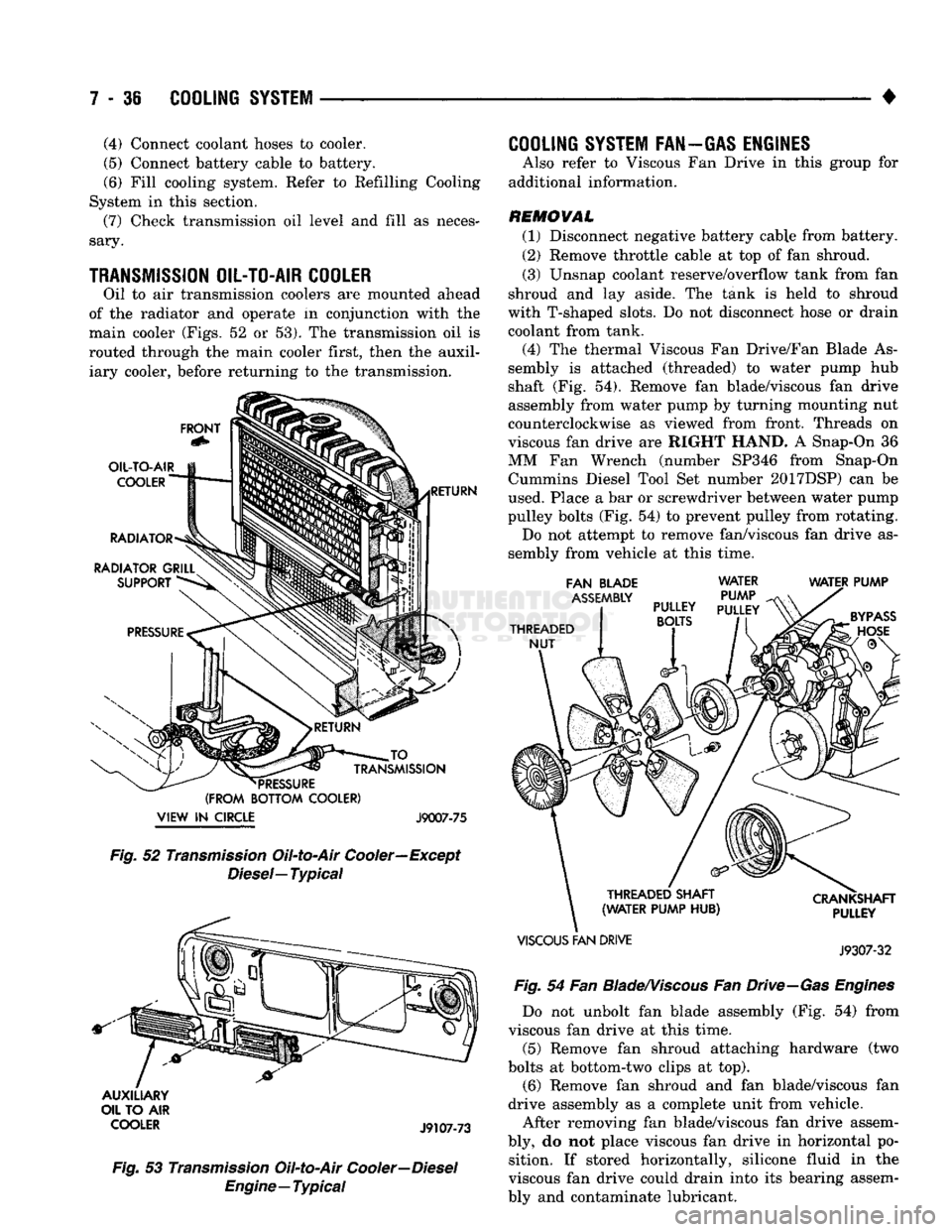
Oil to air transmission coolers are mounted ahead
of the radiator and operate in conjunction with the
main cooler (Figs, 52 or 53). The transmission oil is
routed through the main cooler first, then the auxil iary cooler, before returning to the transmission.
FRONT
OIL-TO-AIR
COOLER
RADIATOR
RADIATOR GRILL SUPPORT RETURN JO
_
TRANSMISSION
*
PRESSURE
(FROM BOTTOM COOLER)
VIEW
IN
CIRCLE J9007-75 Fig.
52
Transmission
Oil-to-Air Cooler—Except
Diesel—
Typical
AUXILIARY
OIL TO AIR
COOLER
J9107-73
Fig.
53
Transmission
Oil-to-Air
Cooler—Diesel
Engine—Typical
COOLING
SYSTEM FAN—GAS ENGINES
Also refer to Viscous Fan Drive in this group for
additional information.
REMOVAL (1) Disconnect negative battery cable from battery.
(2) Remove throttle cable at top of fan shroud.
(3) Unsnap coolant reserve/overflow tank from fan
shroud and lay aside. The tank is held to shroud
with T-shaped slots. Do not disconnect hose or drain
coolant from tank.
(4) The thermal Viscous Fan Drive/Fan Blade As
sembly is attached (threaded) to water pump hub
shaft (Fig. 54). Remove fan blade/viscous fan drive
assembly from water pump by turning mounting nut
counterclockwise as viewed from front. Threads on
viscous fan drive are RIGHT HAND. A Snap-On 36
MM Fan Wrench (number SP346 from Snap-On Cummins Diesel Tool Set number 2017DSP) can be
used. Place a bar or screwdriver between water pump
pulley bolts (Fig. 54) to prevent pulley from rotating. Do not attempt to remove fan/viscous fan drive as
sembly from vehicle at this time.
FAN BLADE
ASSEMBLY
THREADED NUT WATER
PUMP
PULLEY
PULLEY
BOLTS
WATER PUMP
THREADED SHAFT
(WATER PUMP HUB)
VISCOUS
FAN DRIVE CRANKSHAFT
PULLEY
J9307-32
Fig.
54 Fan
Blade/Viscous
Fan
Drive—Gas
Engines
Do not unbolt fan blade assembly (Fig. 54) from
viscous fan drive at this time.
(5) Remove fan shroud attaching hardware (two
bolts at bottom-two clips at top). (6) Remove fan shroud and fan blade/viscous fan
drive assembly as a complete unit from vehicle.
After removing fan blade/viscous fan drive assem
bly, do not place viscous fan drive in horizontal po sition. If stored horizontally, silicone fluid in the
viscous fan drive could drain into its bearing assem
bly and contaminate lubricant.
Page 454 of 1502
•
LAMPS
8L - 11
BULB
APPLICATION
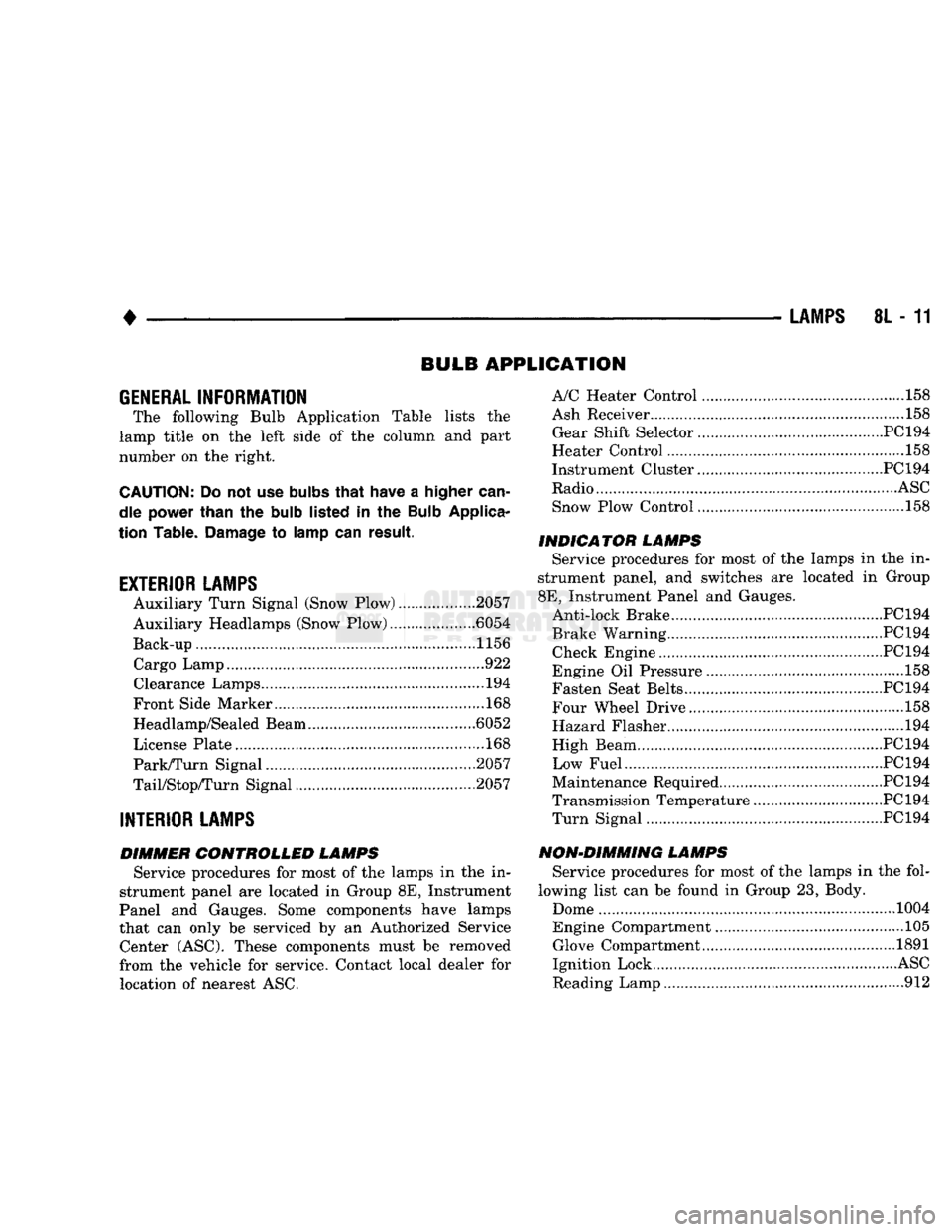
GENERAL
INFORMATION
The following Bulb Application Table lists
the
lamp title
on the
left side
of the
column
and
part
number
on the
right.
CAUTION:
Do not use
bulbs
that
have
a
higher
can
dle power than
the
bulb
listed
in the
Bulb
Applica
tion Table.
Damage
to
lamp
can
result.
EXTERIOR LAMPS
Auxiliary Turn Signal (Snow Plow) 2057
Auxiliary Headlamps (Snow Plow) .6054
Back-up....................... .......1156 Cargo Lamp..
922
Clearance Lamps
194
Front Side Marker
168
Headlamp/Sealed Beam .6052
License Plate
168
Park/Turn Signal 2057
TaiyStop/Turn Signal ...2057
INTERIOR LAMPS
DIMMER CONTROLLED LAMPS Service procedures
for
most
of the
lamps
in the in
strument panel
are
located
in
Group
8E,
Instrument
Panel
and
Gauges. Some components have lamps
that
can
only
be
serviced
by an
Authorized Service Center (ASC). These components must
be
removed
from
the
vehicle
for
service. Contact local dealer
for
location
of
nearest
ASC.
A/C Heater Control
158
Ash Receiver
..158
Gear Shift Selector...........................................PC194
Heater Control
158
Instrument Cluster.. PC 194
Radio
ASC
Snow Plow Control
.158
INDICATOR LAMPS Service procedures
for
most
of the
lamps
in the in
strument panel,
and
switches
are
located
in
Group
8E,
Instrument Panel
and
Gauges. Anti-lock Brake PC194
Brake Warning PC194 Check Engine PC194
Engine
Oil
Pressure
158
Fasten Seat Belts.. PC 194 Four Wheel Drive ....158
Hazard Flasher
194
High Beam PC194
Low Fuel....... JPC194
Maintenance Required PC 194
Transmission Temperature ..PC 194 Turn Signal PC194
NON-DIMMING LAMPS Service procedures
for
most
of the
lamps
in the
fol
lowing list
can be
found
in
Group
23,
Body.
Dome
1004
Engine Compartment ...105 Glove Compartment....
1891
Ignition Lock
ASC
Reading Lamp
912
Page 799 of 1502
13
- 12
FRAME AND BUMPERS
TO FRONT
END
WIRING
(SEE
SH
21)
T
T
18BK
18BK
YL* TO HEADLAMP
Jr
SWITCH -L2
14LG
TO FRONT
END
WIRING
(SEE
SH
22)
BLACK (RIGHT
SIDE
RADIATOR
YOKE
PANEL) BLACK
(RIGHT
' UPPER
SNOW
PLOW
FRAME)
BLACK
LEFT
AUXILIARY
PARK AND
TURN
SIGNAL LAMP
LEFT
AUXILIARY
HEADLAMP
RIGHT
AUXILIARY
HEADLAMP
RIGHT
AUXILIARY
PARK AND
TURN
SIGNAL LAMP
8901-2
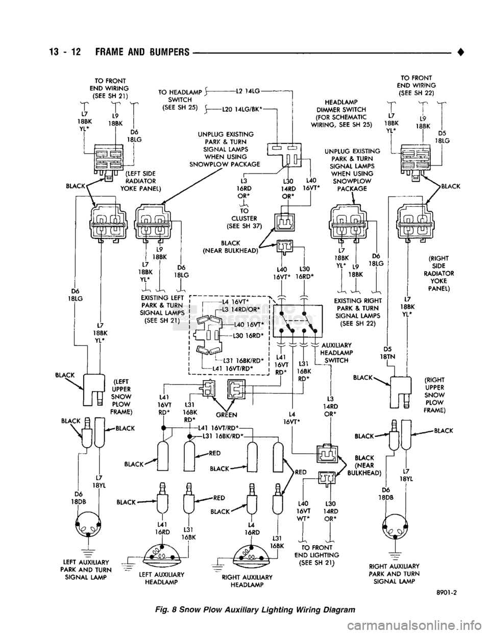
Fig. 8
Snow
Plow
Auxiliary
Lighting Wiring Diagram