1993 DODGE TRUCK air bleeding
[x] Cancel search: air bleedingPage 195 of 1502
i - 8
BRAKES
•
BRAKE
SHOE'S
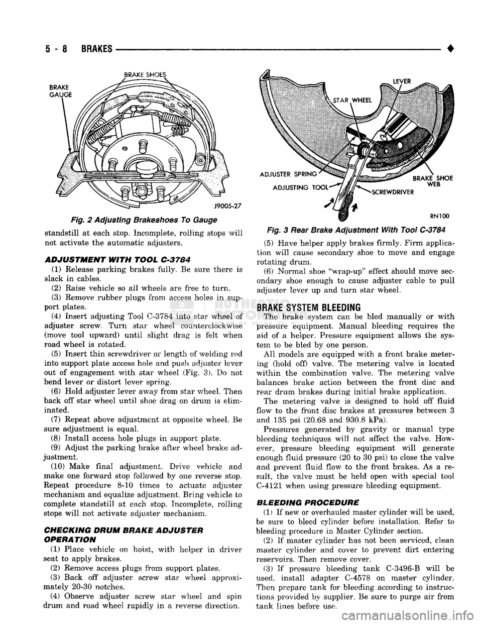
Fig. 2 Adjusting Brakeshoes To Gauge standstill at each stop. Incomplete, rolling stops will
not activate the automatic adjusters.
ADJUSTMENT
WITH
TOOL
C-3784
(1) Release parking brakes fully. Be sure there is
slack in cables. (2) Raise vehicle so all wheels are free to turn.
(3) Remove rubber plugs from access holes in sup
port plates. (4) Insert adjusting Tool
0-3784
into star wheel of
adjuster screw. Turn star wheel counterclockwise
(move tool upward) until slight drag is felt when
road wheel is rotated.
(5)
Insert thin screwdriver or length of welding rod
into support plate access hole and push adjuster lever
out of engagement with star wheel (Fig. 3). Do not
bend lever or distort lever spring.
(6) Hold adjuster lever away from star wheel. Then
back off star wheel until shoe drag on drum is elim inated.
(7) Repeat above adjustment at opposite wheel. Be
sure adjustment is equal. (8) Install access hole plugs in support plate.
(9) Adjust the parking brake after wheel brake ad
justment.
(10) Make final adjustment. Drive vehicle and
make one forward stop followed by one reverse stop.
Repeat procedure 8-10 times to actuate adjuster
mechanism and equalize adjustment. Bring vehicle to
complete standstill at each stop. Incomplete, rolling stops will not activate adjuster mechanism.
CHECKING DRUM
BRAKE ADJUSTER
OPERATION
(1) Place vehicle on hoist, with helper in driver
seat to apply brakes.
(2) Remove access plugs from support plates.
(3) Back off adjuster screw star wheel approxi
mately 20-30 notches. (4) Observe adjuster screw star wheel and spin
drum and road wheel rapidly in a reverse direction. Fig. 3 Rear Brake Adjustment With Tool
C-3784
(5) Have helper apply brakes firmly. Firm applica
tion will cause secondary shoe to move and engage rotating drum.
(6) Normal shoe "wrap-up" effect should move sec
ondary shoe enough to cause adjuster cable to pull adjuster lever up and turn star wheel.
BRAKE
SYSTEM BLEEDING
The brake system can be bled manually or with
pressure equipment. Manual bleeding requires the aid of a helper. Pressure equipment allows the sys
tem to be bled by one person. All models are equipped with a front brake meter
ing (hold off) valve. The metering valve is located
within the combination valve. The metering valve balances brake action between the front disc and
rear drum brakes during initial brake application. The metering valve is designed to hold off fluid
flow to the front disc brakes at pressures between 3 and 135 psi (20.68 and 930.8 kPa). Pressures generated by gravity or manual type
bleeding techniques will not affect the valve. How ever, pressure bleeding equipment will generate
enough fluid pressure (20 to 30 psi) to close the valve and prevent fluid flow to the front brakes. As a re
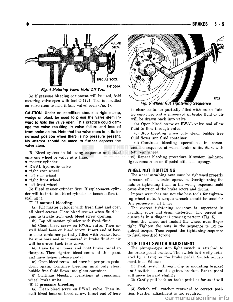
sult, the valve must be held open with special tool
C-4121 when using pressure bleeding equipment.
BLEEDING PROCEDURE (1) If new or overhauled master cylinder will be used,
be sure to bleed cylinder before installation. Refer to
bleeding procedure in Master Cylinder section. (2) If master cylinder has not been serviced, clean
master cylinder and cover to prevent dirt entering
reservoirs. Then remove cover.
(3) If pressure bleeding tank C-3496-B will be
used, install adapter C-4578 on master cylinder.
Then prepare tank for bleeding according to instruc
tions provided by supplier. Be sure to purge air from
tank lines before use.
Page 196 of 1502
BRAKES
i - 9
Fig.
4 Metering
Valve
Hold
Off Tool (4) If pressure bleeding equipment will be used, hold
metering valve open with tool C-4121. Tool is installed on valve stem to hold it (and valve) open (Fig. 4).
CAUTION:
Under
no
condition should
a
rigid clamp,
wedge
or
block
be
used
to
press
the
valve stem
in
ward
to
hold
the
valve open. This
practice
could dam
age
the
valve resulting
in
valve
failure and
loss
of
front
brake action. Note
that the
valve stem
is in its in
nermost position when
there
is no
pressure present.
No
attempt
should
be
made
to further
depress
the
valve stem.
(5) Bleed system in following sequence and bleed
only one wheel or valve at a time:
• master cylinder • RWAL hydraulic valve
• right rear wheel
• left rear wheel
• right front wheel • left front wheel (6) Bleed master cylinder first. If replacement cylin
der will be installed, bleed cylinder on bench before in stalling it.
(7) If manual bleeding: (a) Fill master cylinder with fresh fluid and open
all bleed screws. Close bleed screws when fluid be
gins to trickle from each bleed screw opening. (b) Top off master cylinder with fresh fluid.
(c) Clean bleed screw on RWAL valve. Then in
stall bleed hose on bleed screw. Insert end of hose
in clear container partially filled with brake fluid.
Be sure hose end is immersed in brake fluid or air
will be drawn back into valve.
(d) Have helper press and hold brake pedal to
floorpan. Then tighten bleed screw at this point and have helper release pedal.
(e) Open bleed screw and have helper press pedal
down again. Continue bleeding until only clear,
bubble free fluid flows into glass container. (f) Continue bleeding operations at remaining
wheel brake units.
(8) If pressure bleeding: (a) Clean bleed screw on RWAL valve. Then in
stall bleed hose on bleed screw. Insert end of hose in clear container partially filled with brake fluid.
Be sure hose end is immersed in brake fluid or air
will be drawn back into valve.
(b) Open bleed screw at RWAL valve and allow
fluid to flow through valve.
(c) Stop bleeding when only clear, bubble free
fluid flows into fluid container.
(d) Continue bleeding operations in recom
mended sequence at wheel brake units. Start with
left rear wheel.
(9) Repeat bleeding procedure if system indicator
lights remain on or if pedal still feels spongy.
WHEEL
NUT
TIGHTENING
The wheel attaching nuts must be tightened properly
to ensure efficient brake operation. Overtightening the nuts or tightening them in the wrong sequence could
cause distortion of the brake rotors and drums.
Impact wrenches are not the best tools for tighten
ing wheel nuts. A torque wrench should be used for
this purpose at all times.
The correct tightening sequence is important in
avoiding rotor and drum distortion. The correct se
quence is in a diagonal crossing pattern (Fig. 5). Seat the wheel and install the wheel nuts finger
tight. Tighten the nuts in the sequence to 1/2 re quired torque. Then repeat the tightening sequence
to final specified torque.
STOP
LIGHT SWITCH ADJUSTMENT
The plunger-type stop light switch is attached to
the brake pedal bracket. The switch is directly actu ated by a tang on the brake pedal. Switch adjust
ment is as follows: (1) Push switch through clip in mounting bracket
until switch is sealed against bracket. Brake pedal
will move forward slightly.
(2) Gently pull back on brake pedal as far as it will
go.
(3) Switch will ratchet rearward to correct posi
tion. Further adjustment is not required.
Page 197 of 1502
S
- 10
BRAKES
•
MASTER CYLINDER—COMBINATION
VALVE—BRAKE
LINES
INDEX
page
Bleeding
New
or
Overhauled Master Cylinder
. . . 12
Brake
Lines
and
Hoses
13
Combination Valve Operation
13
Combination Valve Removal/Installation
........
13
Combination Valve Testing
.................
13
page
General
Information
. 10
Master
Cylinder
Installation
12
Master
Cylinder Removal
10
Master
Cylinder Service—Integral Cylinder
11
Master
Cylinder Service—Two-Section Cylinder
. . 11
GENERAL
INFORMATION
Two types
of
master cylinder
are
used
on AD
mod
els.
A
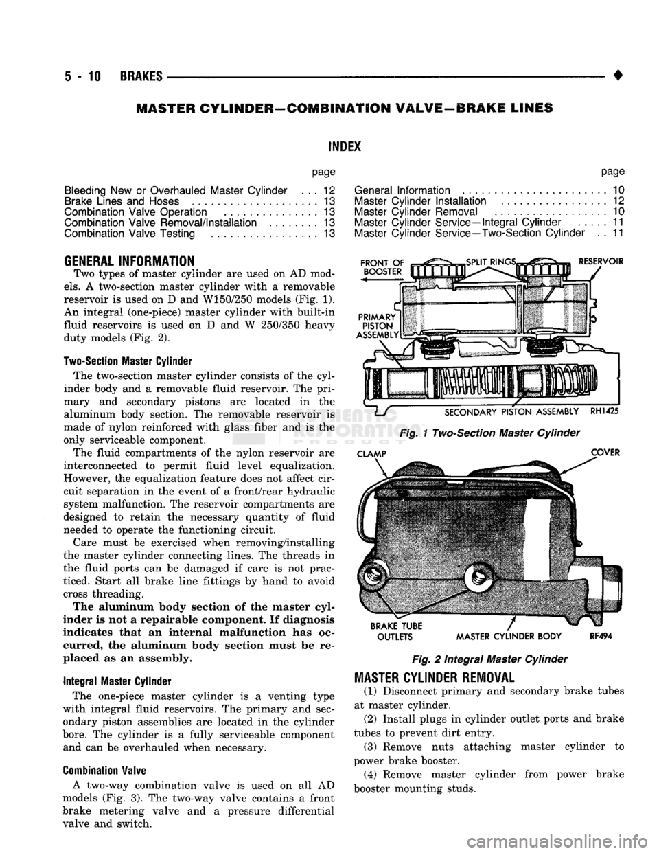
two-section master cylinder with
a
removable
reservoir
is
used
on D and
W150/250 models
(Fig.
1).
An integral (one-piece) master cylinder with built-in
fluid reservoirs
is
used
on D and W
250/350 heavy duty models
(Fig.
2).
Two-Section
Master
Cylinder
The two-section master cylinder consists
of
the
cyl
inder body
and a
removable fluid reservoir.
The
pri
mary
and
secondary pistons
are
located
in the
aluminum body section.
The
removable reservoir
is
made
of
nylon reinforced with glass fiber
and is the
only serviceable component.
The fluid compartments
of the
nylon reservoir
are
interconnected
to
permit fluid level equalization.
However,
the
equalization feature does
not
affect cir
cuit separation
in the
event
of a
front/rear hydraulic
system malfunction.
The
reservoir compartments
are
designed
to
retain
the
necessary quantity
of
fluid
needed
to
operate
the
functioning circuit.
Care must
be
exercised when removing/installing
the master cylinder connecting lines.
The
threads
in
the fluid ports
can be
damaged
if
care
is not
prac
ticed. Start
all
brake line fittings
by
hand
to
avoid cross threading.
The aluminum body section
of the
master cyl
inder
is not a
repairable component.
If
diagnosis
indicates that
an
internal malfunction
has oc
curred,
the
aluminum body section must
be re
placed
as an
assembly.
Integral
Master Cylinder
The one-piece master cylinder
is a
venting type
with integral fluid reservoirs.
The
primary
and
sec
ondary piston assemblies
are
located
in the
cylinder
bore.
The
cylinder
is a
fully serviceable component and
can be
overhauled when necessary.
Combination
Valve
A two-way combination valve
is
used
on all AD
models
(Fig.
3). The
two-way valve contains
a
front
brake metering valve
and a
pressure differential valve
and
switch.
OUTLETS MASTER CYLINDER BODY
RF494
Fig.
2
Integral Master Cylinder
MASTER
CYLINDER REMOVAL
(1) Disconnect primary
and
secondary brake tubes
at master cylinder. (2) Install plugs
in
cylinder outlet ports
and
brake
tubes
to
prevent dirt entry. (3) Remove nuts attaching master cylinder
to
power brake booster. (4) Remove master cylinder from power brake
booster mounting studs.
Page 199 of 1502
i - 12
BRAKES
•
Fig.
6 integral Cylinder
Components
Cylinder Cleaning And Inspection Clean the cylinder body and cover with brake fluid
or brake cleaner only. Do not use any other type of solvents, or cleaning agent. Inspect the cylinder body and bore. Light discolor
ation of the cylinder bore is normal and is an accept
able condition. The bore should be smooth and free of
scores, scratches, corrosion and rust. Replace the cyl
inder if the bore is worn, scored, or corroded.
Do not hone the bore in an attempt to restore the
surface finish. Replace the cylinder if the bore is
damaged in any way. Also replace the cylinder if the
body is cracked, porous, or the compensator port at
the bottom of each reservoir is blocked or damaged.
Inspect the cover and gasket. Replace the gasket if
distorted, cut, or torn. Replace the cover and retain
ing wire if either component is distorted or damaged
in any way.
Do not reuse the old piston assemblies. Discard
these parts as soon as they are removed. Install re
placement primary and secondary piston assemblies
only.
INTEGRAL
CYLINDER ASSEMBLY
(1) Coat cylinder bore and replacement piston as
semblies with liberal quantity of clean brake fluid.
(2) Install secondary piston assembly in bore with
a turning motion. Do not use metal tools of any kind
to help ease piston into bore. Sharp edge tools will
scratch bore and cut piston seals.
(3) If cylinder is equipped with stop screw for sec
ondary piston, press piston to bottom of bore and in
stall screw.
(4) Install primary piston in bore.
(5) Press pistons inward with wood dowel and in
stall piston snap ring. Be sure snap ring is fully
seated.
(6) Install new gasket on cover if necessary.
(7) Install cover retaining wire on cylinder if re
moved. (8) Fill and bleed master cylinder on bench before
installing it in vehicle. Refer to following procedure.
BLEEDING
NEW
OR
OVERHAULED MASTER
CYLINDER
A new or overhauled master cylinder should be
purged of all air before installation on the vehicle. Cylinder bleeding is performed on the bench. Bleeding tools for the integral master cylinder in
clude fabricated bleed tubes and a wood dowel.
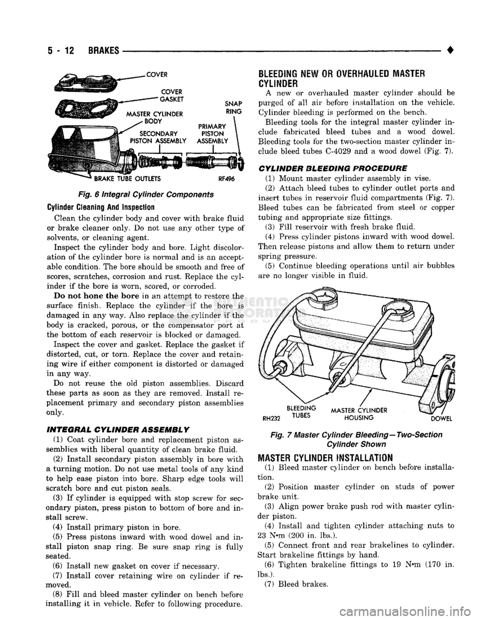
Bleeding tools for the two-section master cylinder in clude bleed tubes C-4029 and a wood dowel (Fig. 7).
CYLINDER BLEEDING PROCEDURE
(1) Mount master cylinder assembly in vise.
(2) Attach bleed tubes to cylinder outlet ports and
insert tubes in reservoir fluid compartments (Fig. 7).
Bleed tubes can be fabricated from steel or copper
tubing and appropriate size fittings.
(3) Fill reservoir with fresh brake fluid. (4) Press cylinder pistons inward with wood dowel.
Then release pistons and allow them to return under spring pressure.
(5) Continue bleeding operations until air bubbles
are no longer visible in fluid.
Fig.
7 Master Cylinder
Bleeding—
Two-Section
Cylinder
Shown
MASTER
CYLINDER INSTALLATION
(1) Bleed master cylinder on bench before installa
tion. (2) Position master cylinder on studs of power
brake unit. (3) Align power brake push rod with master cylin
der piston. (4) Install and tighten cylinder attaching nuts to
23 N-m (200 in. lbs.). (5) Connect front and rear brakelines to cylinder.
Start brakeline fittings by hand. (6) Tighten brakeline fittings to 19 N«m (170 in.
lbs.).
(7) Bleed brakes.
Page 911 of 1502
14-92
FUEL
SYSTEM
• A broken injection pump timing mechanism spring
will cause the timing to be fully advanced resulting
in torque loss, a fuel knock and possible engine over
heating.
An improperly operating KSB (cold start) solenoid
will cause white smoke during engine warm-up. The
KSB solenoid is not serviceable.
A defective or non-adjustable fuel injection pump
can cause starting problems or prevent the engine
from revving up. It can also cause:
• Engine surge at idle • Rough idle (warm engine)
• Engine miss under load
• Low power
• Excessive fuel consumption
• Poor performance
• Low power
• Black smoke from the exhaust • Blue or white fog like exhaust
• Incorrect idle or maximum speed A worn fuel injection pump plunger can effect fuel
pressure and the amount of fuel injected. This results in reduced engine power. In most cases, if the injec
tion pump is delivering fuel from one outlet, it will deliver fuel from all outlets. If the internal plunger is defective, the fuel injection pump must be re
placed.
Engine power is also effected by the governor set
ting and performance. Do not attempt to adjust the governor. If the governor seals on the external adjustment screw are broken, the fuel rate may
be out of adjustment. The warranty of the injec tion pump and the engine may be void if the
seals have been tampered with or removed.
FUEL
INJECTORS
A leaking fuel injector can cause fuel knock, poor
performance, black smoke, poor fuel economy and
rough engine idle. If the fuel injector needle valve
does not operate properly, the engine may misfire and produce low power. A leak in the injection pump-to-injector high pres
sure fuel line can cause many of the same symptoms as a malfunctioning injector. Inspect for a leak in the
high pressure lines before checking for a malfunc
tioning fuel injector.
WARNING:
THE
INJECTION PUMP SUPPLIES HIGH
PRESSURE
FUEL
OF
APPROXIMATELY
59,000
KPA
(8,000
PSI) TO
EACH INDIVIDUAL INJECTOR
THROUGH THE HIGH
PRESSURE
LINES. FUEL UN
DER
THIS AMOUNT
OF
PRESSURE
CAN
PENE
TRATE THE SKIN AND CAUSE PERSONAL INJURY,
WEAR
SAFETY GOGGLES
AND
ADEQUATE PRO
TECTIVE CLOTHING. AVOID CONTACT
WITH
FUEL
SPRAY
WHEN BLEEDING HIGH
PRESSURE
FUEL
LINES.
WARNING:
DO NOT
BLEED
AIR
FROM
THE
FUEL
SYSTEM
OF A
HOT ENGINE.
DO
NOT ALLOW FUEL
TO SPRAY ONTO THE EXHAUST MANIFOLD WHEN
BLEEDING
AIR
FROM THE FUEL SYSTEM.
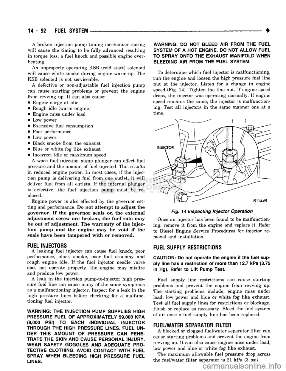
To determine which fuel injector is malfunctioning,
run the engine and loosen the high pressure fuel line nut at the injector. Listen for a change in engine
speed (Fig. 14). Tighten the line nut. If engine speed
drops,
the injector was operating normally. If engine
speed remains the same, the injector is malfunction
ing. Test all injectors in the same manner one at a
time.
Fig. 14
Inspecting
Injector Operation
Once an injector has been found to be malfunction
ing, remove it from the engine and replace it. Refer
to Diesel Engine Service Procedures for injector re moval and installation.
FUEL
SUPPLY
RESTRICTIONS
CAUTION:
Do not
operate
the
engine
if the
fuel
sup ply
line
has
a
restriction
of
more
than
12.7
kPa
(3.75
in
Hg).
Refer
to
Lift
Pump
Test.
Fuel supply line restrictions can cause starting
problems and prevent the engine from revving up.
The starting problems include; engine miss under load, low power and blue or white fog like exhaust.
Test all fuel supply lines for restrictions or blockage.
Flush or replace as necessary. Bleed the fuel system
of air once a fuel supply line has been replaced.
FUEL/WATER
SEPARATOR
FILTER
A blocked or clogged fuel/water separator filter can
cause starting problems and prevent the engine from
revving up. It can also cause engine miss under load,
low power and blue or white fog like exhaust. The maximum allowable fuel pressure drop across
the fuel/water filter separator is 21 kPa (3 psi).
Page 912 of 1502
•
FUEL SYSTEM
14-93 There is a drain at the bottom of the separator fil
ter (Fig. 13). Place a drain pan under the drain tube. With the engine not running, hold the drain open
until all water and contaminants have been removed and clean fuel exits the drain. Dispose of mixture in
drain pan according to applicable regulations.
If excess water gathers in separator/filter in a short
time,
the fuel tank must be removed, drained and cleaned.
HIGH
PRESSURE FUEL LINE RESTRICTIONS
High pressure fuel line leaks can cause starting
problems, poor engine performance and engine miss under load. Restricted high pressure lines can cause starting problems, poor engine performance, engine
miss under load and black smoke from exhaust.
WARNING:
USE
EXTREME
CAUTION
WHEN
IN
SPECTING
FOR HIGH
PRESSURE
FUEL
LEAKS.
IN
SPECT
FOR HIGH
PRESSURE
FUEL
LEAKS
WITH
A
SHEET
OF
CARDBOARD.
HIGH
FUEL
INJECTION
PRESSURE
CAN
CAUSE
PERSONAL
INJURY
IF
CONTACT
IS
MADE
WITH
THE
SKIN.
Start the engine. Move the cardboard over the high
pressure fuel lines and check for fuel spray onto the cardboard. If a high pressure line connection is leak
ing, bleed the system and tighten the connection. Re
fer to the 5.9L Diesel Service Procedures section for air bleeding procedures. Replace damaged, restricted
or leaking high pressure fuel lines with the correct replacement line.
CAUTION:
The
high pressure
fuel
lines must
be
clamped securely
in
place
in the
holders.
The
lines cannot contact each other
or
other components.
Do
not
attempt
to
weld high pressure
fuel
lines
or to
repair lines
that
are
damaged. Only
use the
recom
mended lines when replacement
of
high pressure
fuel
line
is
necessary.
KSB
SOLENOID
The KSB solenoid will click when it is energized
and de-energized. If the solenoid does not click when 12 volts is sup
plied to it, replace the solenoid.
MECHANICAL
LIFT
PUMP
An improperly operating lift pump can cause low
engine power. Inspect the fuel supply line to the
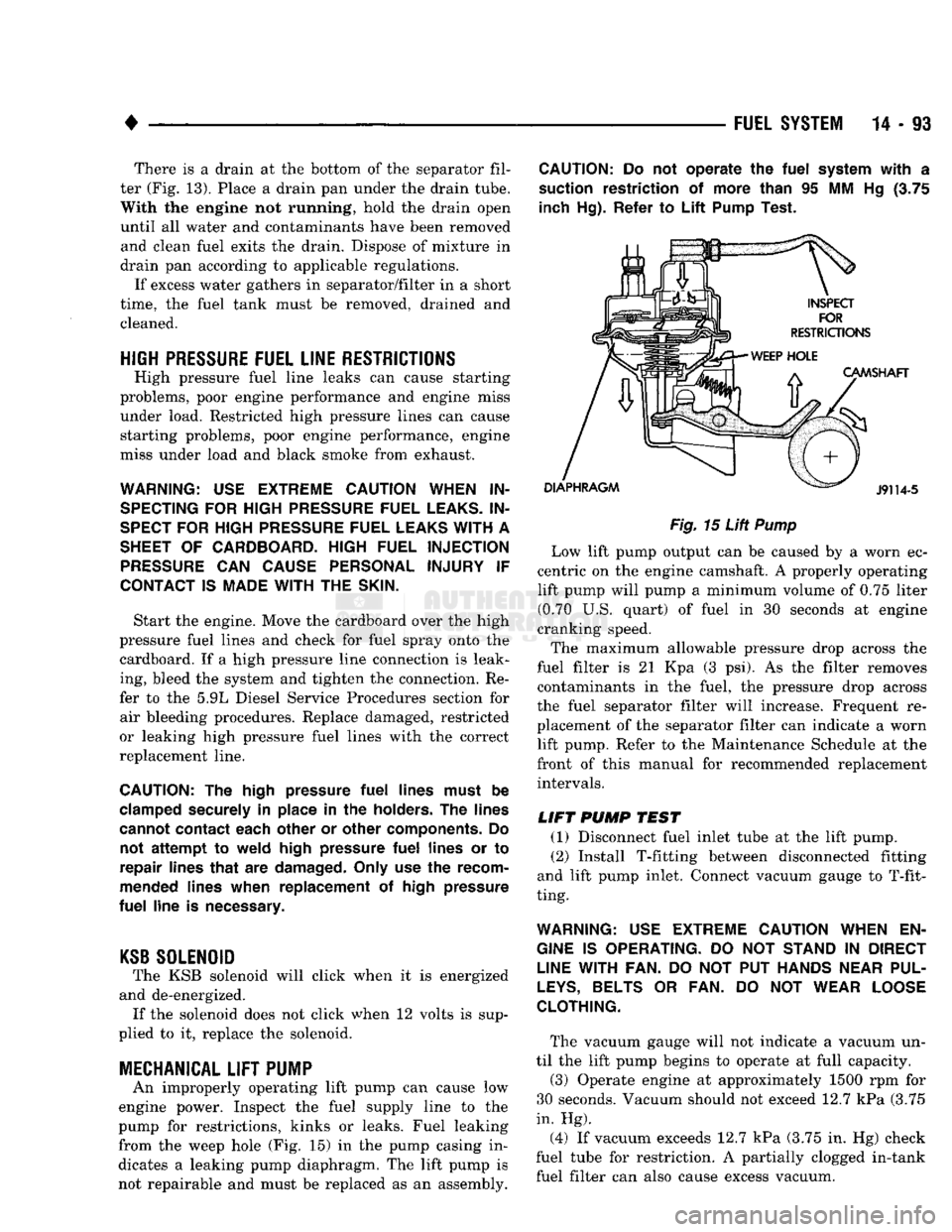
pump for restrictions, kinks or leaks. Fuel leaking
from the weep hole (Fig. 15) in the pump casing in
dicates a leaking pump diaphragm. The lift pump is not repairable and must be replaced as an assembly.
CAUTION:
Do not
operate
the
fuel
system
with
a
suction restriction
of
more than
95 MM Hg (3.75
inch Hg). Refer
to
Lift
Pump Test.
Fig.
15
Lift
Pump
Low lift pump output can be caused by a worn ec
centric on the engine camshaft. A properly operating lift pump will pump a minimum volume of 0.75 liter (0.70 U.S. quart) of fuel in 30 seconds at engine
cranking speed.
The maximum allowable pressure drop across the
fuel filter is 21 Kpa (3 psi). As the filter removes contaminants in the fuel, the pressure drop across
the fuel separator filter will increase. Frequent re
placement of the separator filter can indicate a worn lift pump. Refer to the Maintenance Schedule at the
front of this manual for recommended replacement intervals.
LIFT
PUMP
TEST
(1) Disconnect fuel inlet tube at the lift pump. (2) Install T-fitting between disconnected fitting
and lift pump inlet. Connect vacuum gauge to T-fit
ting.
WARNING:
USE
EXTREME
CAUTION
WHEN
EN
GINE
IS
OPERATING.
DO NOT
STAND
IN
DIRECT
LINE
WITH FAN.
DO NOT PUT
HANDS
NEAR
PUL
LEYS,
BELTS
OR FAN. DO NOT
WEAR
LOOSE
CLOTHING.
The vacuum gauge will not indicate a vacuum un
til the lift pump begins to operate at full capacity.
(3) Operate engine at approximately 1500 rpm for
30 seconds. Vacuum should not exceed 12.7 kPa (3.75
in. Hg).
(4) If vacuum exceeds 12.7 kPa (3.75 in. Hg) check
fuel tube for restriction. A partially clogged in-tank fuel filter can also cause excess vacuum.
Page 925 of 1502
14
- 106
FUEL SYSTEi
DIESEL FUEL
INJECTION-SERVICE
PROCEDURES
INDEX
page
Air Bleed Procedure
106
Air Fuel Control Tube
107
Air Intake Heater
107
Engine
Speed
Sensor
108
Fuel Drain Manifold
109
Fuel Heater
. 110
Fuel
Injection
Pump
110
Fuel
Injection
Pump Supply Line
114
Fuel
Injectors
114
AIR BLEED PROCEDURE
A certain amount
of air
becomes trapped
in the
fuel system when fuel system components
are
ser
viced
or
replaced. Bleed
the
system after fuel system service according
to the
following procedures.
WARNING:
DO NOT
BLEED
AIR
FROM
THE
FUEL
SYSTEM
OF
A
HOT
ENGINE.
DO
NOT
ALLOW FUEL
TO SPRAY ONTO
THE
EXHAUST MANIFOLD WHEN BLEEDING
AIR
FROM
THE
FUEL SYSTEM.
MANUAL BLEEDING
Some
air
enters
the
fuel system when
the
filters
or
injection pump supply line
are
changed. This small
amount
of air is
vented automatically from
the
injec
tion pump through
the
fuel drain manifold. This
is if
the filter
was
changed according
to
instructions.
The system will have
to be
bleed manually
if:
•
The
fuel filter
is not
filled before installation
•
Injection pump
is
replaced
•
High pressure fuel line connections
are
loosened
or
lines replaced
•
Initial engine start-up
or
start-up after
an ex
tended period
of no
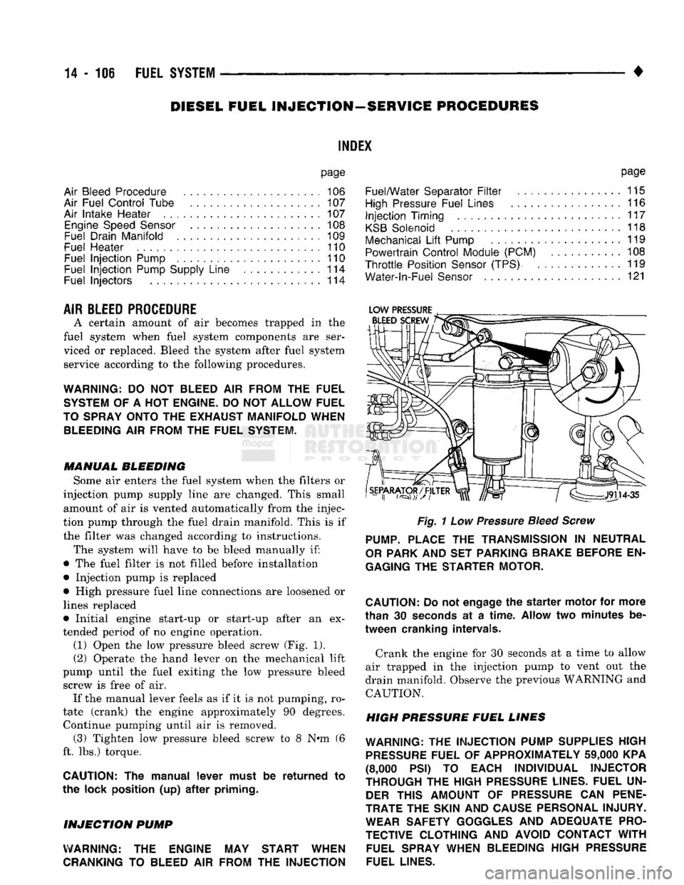
engine operation. (1) Open
the low
pressure bleed screw
(Fig. 1).
(2) Operate
the
hand lever
on the
mechanical lift
pump until
the
fuel exiting
the low
pressure bleed screw
is
free
of air.
If
the
manual lever feels
as if it is not
pumping,
ro
tate (crank)
the
engine approximately
90
degrees. Continue pumping until
air is
removed. (3) Tighten
low
pressure bleed screw
to 8 N»m (6
ft.
lbs.)
torque.
CAUTION:
The
manual lever must
be
returned
to
the lock position
(up) after
priming.
INJECTION
PUMP
WARNING:
THE
ENGINE
MAY
START WHEN
CRANKING
TO
BLEED
AIR
FROM
THE
INJECTION
page
Fuel/Water Separator
Filter
................
115
High
Pressure Fuel Lines
116
Injection
Timing
117
KSB
Solenoid
118
Mechanical
Lift
Pump
119
Powertrain Control Module (PCM)
108
Throttle
Position
Sensor
(TPS)
119
Water-ln-Fuel
Sensor
121
Fig.
1
Low
Pressure
Bleed Screw
PUMP.
PLACE
THE
TRANSMISSION
IN
NEUTRAL
OR
PARK
AND SET
PARKING BRAKE BEFORE
EN
GAGING
THE
STARTER MOTOR.
CAUTION:
Do
not
engage
the
starter
motor
for
more
than
30
seconds
at a
time.
Allow
two
minutes
be
tween cranking intervals.
Crank
the
engine
for 30
seconds
at a
time
to
allow
air trapped
in the
injection pump
to
vent
out the
drain manifold. Observe
the
previous WARNING
and
CAUTION.
HIGH PRESSURE FUEL LINES
WARNING:
THE
INJECTION PUMP SUPPLIES HIGH
PRESSURE
FUEL
OF
APPROXIMATELY
59,000
KPA
(8,000
PSI) TO
EACH INDIVIDUAL INJECTOR
THROUGH
THE
HIGH
PRESSURE
LINES. FUEL
UN
DER
THIS AMOUNT
OF
PRESSURE
CAN
PENE
TRATE
THE
SKIN
AND
CAUSE PERSONAL INJURY. WEAR SAFETY GOGGLES
AND
ADEQUATE PRO
TECTIVE CLOTHING
AND
AVOID CONTACT
WITH
FUEL SPRAY WHEN BLEEDING HIGH
PRESSURE
FUEL LINES.
Page 926 of 1502
•
FUEL SYSTEM 14 - 107
WARNING;
DO NOT
BLEED
AIR
FROM
THE
FUEL
SYSTEM
OF A HOT
ENGINE.
DO NOT
ALLOW FUEL
TO SPRAY ONTO
THE
EXHAUST MANIFOLD WHEN
BLEEDING
AIR
FROM
THE
FUEL SYSTEM.
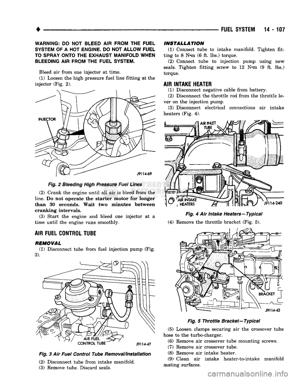
Bleed air from one injector at time. (1) Loosen the high pressure fuel line fitting at the
injector (Fig. 2).
Fig.
2
Bleeding
High Pressure Fuel Lines
(2) Crank the engine until all air is bleed from the
line.
Do not operate the starter motor for longer
than 30 seconds. Wait two minutes between cranking intervals.
(3) Start the engine and bleed one injector at a
time until the engine runs smoothly.
AIR
FUEL CONTROL TUBE
REMOWAL
(1) Disconnect tube from fuel injection pump (Fig.
3). Fig.
3 Air
Fuel
Control Tube Removal/Installation
(2) Disconnect tube from intake manifold.
(3) Remove tube. Discard seals.
INSTALLATION
(1) Connect tube to intake manifold. Tighten fit
ting to 8 Nnn (6 ft. lbs.) torque. (2) Connect tube to injection pump using new
seals.
Tighten fitting screw to 12 Nnn (9 ft. lbs.)
torque.
AIR INTAKE HEATER
(1) Disconnect negative cable from battery.
(2) Disconnect the throttle rod from the throttle le
ver on the injection pump. (3) Disconnect electrical connections air intake
heaters (Fig. 4).
Fig.
4 Air Intake Heaters—Typical
(4) Remove the throttle bracket (Fig. 5).
Fig.
5
Throttle
Bracket—Typical
(5) Loosen clamps securing air the crossover tube
hose to the turbo-charger.
(6) Remove air crossover tube mounting screws.
(7) Remove air crossover tube.
(8) Remove air intake heater.
(9) Clean air intake heater-to-intake manifold
mating surfaces.