1993 DODGE TRUCK length
[x] Cancel search: lengthPage 661 of 1502
9
- 56 5.2L
ENGINE
•
VALVE
SPRING
RETAINER LOCK GROOVE
EXHAUST
VALVE
J9209-127 the spring load at test length. Fractional measure
ments are indicated on the table for finer adjust
ments. Refer to specifications to obtain specified
height and allowable tensions. Discard the springs
that do not meet specifications.
SPECIAL
TOOL
C-647
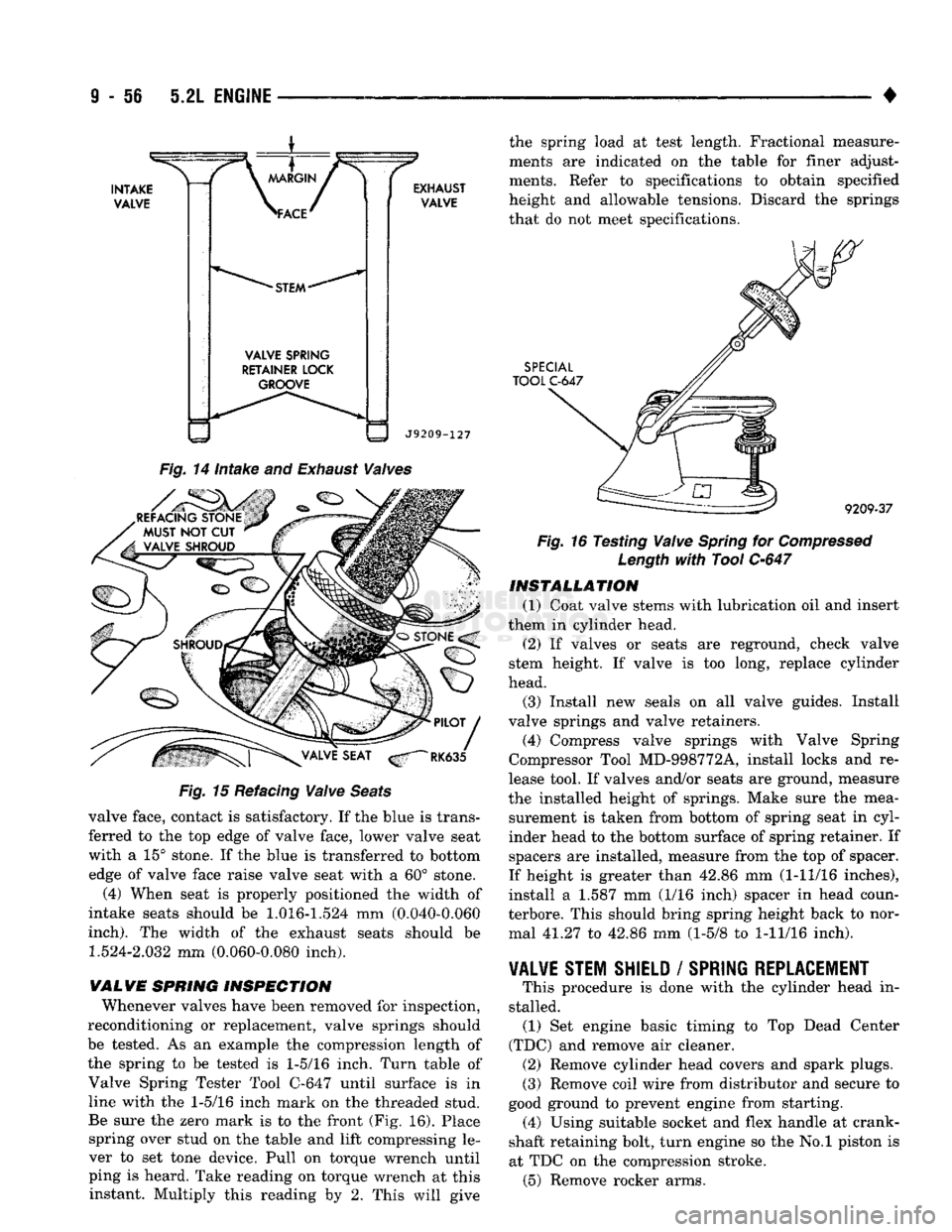
Fig.
14 Intake and
Exhaust
Valves
Fig.
15 Refacing
Valve
Seats
valve face, contact is satisfactory. If the blue is trans
ferred to the top edge of valve face, lower valve seat
with a 15° stone. If the blue is transferred to bottom edge of valve face raise valve seat with a 60° stone.
(4) When seat is properly positioned the width of
intake seats should be
1.016-1.524
mm (0.040-0.060
inch).
The width of the exhaust seats should be
1.524-2.032
mm (0.060-0.080 inch).
WALVE SPRING INSPECTION Whenever valves have been removed for inspection,
reconditioning or replacement, valve springs should
be tested. As an example the compression length of
the spring to be tested is
1-5/16
inch. Turn table of Valve Spring Tester Tool C-647 until surface is in line with the
1-5/16
inch mark on the threaded stud.
Be sure the zero mark is to the front (Fig. 16). Place spring over stud on the table and lift compressing le
ver to set tone device. Pull on torque wrench until ping is heard. Take reading on torque wrench at this instant. Multiply this reading by 2. This will give ^
9209-37
Fig.
16 Testing
Valve
Spring
for
Compressed
Length
with
Tool
C-647
INSTALLATION
(1) Coat valve stems with lubrication oil and insert
them in cylinder head.
(2) If valves or seats are reground, check valve
stem height. If valve is too long, replace cylinder
head.
(3) Install new seals on all valve guides. Install
valve springs and valve retainers.
(4) Compress valve springs with Valve Spring
Compressor Tool MD-998772A, install locks and re
lease tool. If valves and/or seats are ground, measure
the installed height of springs. Make sure the mea surement is taken from bottom of spring seat in cyl
inder head to the bottom surface of spring retainer. If spacers are installed, measure from the top of spacer.
If height is greater than 42.86 mm (1-11/16 inches),
install a 1.587 mm (1/16 inch) spacer in head coun-
terbore. This should bring spring height back to nor mal 41.27 to 42.86 mm (1-5/8 to
1-11/16
inch).
VALVE STEM SHIELD
/
SPRING REPLACEMENT
# This procedure is done with the cylinder head in
stalled. (1) Set engine basic timing to Top Dead Center
(TDC) and remove air cleaner. (2) Remove cylinder head covers and spark plugs.
(3) Remove coil wire from distributor and secure to
good ground to prevent engine from starting. (4) Using suitable socket and flex handle at crank
shaft retaining bolt, turn engine so the No.l piston is
at TDC on the compression stroke. (5) Remove rocker arms.
Page 662 of 1502
•
5.2L
ENGINE
9 - 57 (6) With air hose attached to an adapter installed
in No.l spark plug hole, apply 620-689 kPa (90-100
psi) air pressure.
(7) Using Valve Spring Compressor Tool
MD-998772A, compress valve spring and remove re
tainer valve locks and valve spring.
(8) Install seals on the exhaust valve stem and po
sition down against valve guides.
(9) The intake valve stem seals should be pushed
firmly and squarely over the valve guide using the valve stem as a guide. DO NOT force seal against
top of guide. When installing the valve retainer
locks,
compress the spring only enough to install the
locks.
(10) Follow the same procedure on the remaining 7
cylinders using the firing sequence 1-8-4-3-6-5-7-2.
Make sure piston in cylinder is at TDC on the valve
spring that is being removed. (11) Remove adapter from the No.l spark plug
hole.
(12) Install rocker arms.
(13) Install covers and coil wire to distributor.
(14) Install air cleaner. (15) Road test vehicle.
HYDRAULIC TAPPETS
Before disassembling any part of the engine to cor
rect tappet noise, check the oil pressure. If vehicle
has no oil pressure gauge, install a reliable gauge at the pressure sending unit. The pressure should be be
tween 207-552 kPa (30-80 psi) at 3,000 RPM. Check the oil level after the engine reaches normal
operating temperature. Allow 5 minutes to stabilize oil level, check dipstick. The oil level in the pan should never be above the
FULL mark or below the ADD OIL mark on dipstick.
Either of these 2 conditions could be responsible for
noisy tappets.
OIL LEWEL
HIGH
If oil level is above the FULL mark, it is possible
for the connecting rods to dip into the oil. With the
engine running this condition could create foam in
the oil pan. Foam in oil pan would be fed to the hy
draulic tappets by the oil pump causing them to lose
length and allow valves to seat noisily.
LOW Low oil level may allow oil pump to take in air.
When air is fed to the tappets, they lose length
which allows valves to seat noisily. Any leaks on in
take side of oil pump through which air can be drawn will create the same tappet action. Check the
lubrication system from the intake strainer to the
pump cover, including the relief valve retainer cap. When tappet noise is due to aeration, it may be in termittent or constant, and usually more than 1 tap
pet will be noisy. When oil level and leaks have been
corrected, operate the engine at fast idle. Run engine
for a sufficient time to allow all of the air inside the
tappets to be bled out.
TAPPET
NOISE DIAGNOSIS
(1) To determine source of tappet noise, operate en
gine at idle with cylinder head covers removed.
(2) Feel each valve spring or rocker arm to detect
noisy tappet. The noisy tappet will cause the affected
spring and/or rocker arm to vibrate or feel rough in
operation.
Worn valve guides or cocked springs are some
times mistaken for noisy tappets. If such is the case, noise may be dampened by applying side
thrust on the valve spring. If noise is not appre
ciably reduced, it can be assumed the noise is in
the tappet. Inspect the rocker arm push rod sockets and push rod ends for wear.
(3) Valve tappet noise ranges from light noise to a
heavy click. A light noise is usually caused by exces sive leak-down around the unit plunger or by the
plunger partially sticking in the tappet body cylin der. The tappet should be replaced. A heavy click is caused by a tappet check valve not seating or by for
eign particles becoming wedged between the plunger and the tappet body. This will cause the plunger to
stick in the down position. This heavy click will be accompanied by excessive clearance between the
valve stem and rocker arm as valve closes. In either
case,
tappet assembly should be removed for inspec
tion and cleaning.
The valve train generates a noise very much like a
light tappet noise during normal operation. Care
must be taken to ensure that tappets are making the
noise. In general, if more than one tappet seems to
be noisy, its probably not the tappets.
REMOVAL
(1) Remove the air cleaner.
(2) Remove cylinder head cover.
(3) Remove rocker assembly and push rods. Iden
tify push rods to ensure installation in original loca
tion.
(4) Remove intake manifold.
(5) Remove yoke retainer and aligning yokes.
(6) Slide Hydraulic Tappet Remover/Installer Tool
C-4129-A through opening in cylinder head and seat
tool firmly in the head of tappet.
(7) Pull tappet out of bore with a twisting motion.
If all tappets are to be removed, identify tappets to
ensure installation in original location.
(8) If the tappet or bore in cylinder block is scored,
scuffed, or shows signs of sticking, ream the bore to
next oversize. Replace with oversize tappet.
Page 670 of 1502
5.2L
ENGINE S - 65
INSPECTION
Mating surface of the oil pump cover should be
smooth. Replace pump assembly if cover is scratched
or grooved.
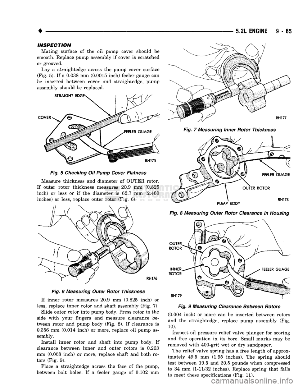
Lay a straightedge across the pump cover surface
(Fig. 5). If a 0.038 mm (0.0015 inch) feeler gauge can
be inserted between cover and straightedge, pump assembly should be replaced.
Fig.
5
Checking
Oil Pump
Cover
Flatness
Measure thickness and diameter of OUTER rotor.
If outer rotor thickness measures 20.9 mm (0.825 inch) or less or if the diameter is 62.7 mm (2.469
inches) or less, replace outer rotor (Fig. 6).
Fig.
6
Measuring
Outer Rotor
Thickness
If inner rotor measures 20.9 mm (0.825 inch) or
less,
replace inner rotor and shaft assembly (Fig. 7).
Slide outer rotor into pump body. Press rotor to the
side with your fingers and measure clearance be
tween rotor and pump body (Fig. 8). If clearance is 0.356 mm (0.014 inch) or more, replace oil pump as
sembly.
Install inner rotor and shaft into pump body. If
clearance between inner and outer rotors is 0.203
mm (0.008 inch) or more, replace shaft and both ro
tors (Fig. 9).
Place a straightedge across the face of the pump,
between bolt holes. If a feeler gauge of 0.102 mm
Fig.
7
Measuring
Inner
Rotor
Thickness
Fig.
8
Measuring
Outer Rotor Clearance in
Housing
OUTER
ROTOR
INNER
ROTOR
RH179
Fig.
9
Measuring
Clearance Between
Rotors
(0.004 inch) or more can be inserted between rotors
and the straightedge, replace pump assembly (Fig.
10).
Inspect oil pressure relief valve plunger for scoring
and free operation in its bore. Small marks may be
removed with 400-grit wet or dry sandpaper.
The relief valve spring has a free length of approx
imately 49.5 mm (1.95 inches). The spring should
test between 19.5 and 20.5 pounds when compressed
to 34 mm (1-11/32 inches). Replace spring that fails
to meet these specifications (Fig. 11).
Page 678 of 1502
SPECIFICATIONS—5.2L
ENGINE
ENGINE SPECIFICATIONS
Camshaft
Bearing Diameter
No.
1....................... . 50.800-50.825 mm (2.000-2.001 in)
No.
2... 50.394-50.419 mm (1.984-1.985 in)
No.
3. . 50.013-50.038 mm
(1.969-1.970
in)
No.
4...........
......... 49.606-49.632 mm (1.953-1.954 in)
No.
5 39.688-39.713 mm
(1.5625-1.5635 in)
Diametrical Clearance 0.0254-0.0762 mm (0.001-0.003 in)
Max. Allowable 0.127 mm (0.005 in)
End Play. . .... 0.051-0.254 mm (0.002-0.010 in)
Bearing Journal Diameter
No.
1....................... . 50.749-50.775 mm (1.998-1.999 in)
No.
2 50.343-50.368 mm
(1.982-1.983
in)
No.
3... 49.962-49.987 mm (1.967-1.968 in)
No.
4. ......... .......... 49.555-49.581 mm (1.951-1.952 in)
No.
5 39.637-39.662 mm
(1.5605-1.5615 in)
Connecting
Rods
Bearing Clearance 0.0127-0.0559 mm (0.0005-0.0022 in)
Piston Pin Bore Diameter . 24.966-24.978 mm (0.9829-0.9834 in)
Side Clearance (Two Rods) ......... 0.152-0.356 mm (0.006-0.014 in)
Total Weight (Less Bearing) ......... 726 grams (25.61 oz)
Crankshaft
Connect Rod Journal Diameter ....... 53.950-53.975 mm (2.124-2.125 in)
Out-of-Round (Max.) ............ 0.0254 mm (0.001 in)
Taper (Max.) .... ...... 0.0254 mm (0.001 in)
Diametrical Clearance
No.
1 0.0127-0.0381 mm (0.0005-0.0015 in)
Nos.
2, 3, 4 and 5 ............. 0.0127-0.0508 mm (0.0005-0.0020 in)
Max. Allowable (Nos. 2, 3,4&5) 0.0635 mm (0.0025 in) End Play 0.051-0.178 mm
(0.002-0.007 in)
Max. Allowable 0.254 mm (0.010 in)
Main Bearing Journals Diameter ..................... 63.487-63.513 mm (2.4995-2.5005 in)
Out-of-Round (Max.) 0.0254 mm (0.001 in)
Taper (Max.) 0.0254 mm (0.001 in)
Cylinder
Block
Cylinder Bore Diameter 99.314-99.365 mm (3.910-3.912 in)
Out-of-Round (Max.) ............ 0.127 mm (0.005 in)
Taper (Max.) 0.254 mm (0.010 in)
Oversize (Max.) ................ 1.016 mm (0.040 in)
Distributor Lower Drive Shaft Bushing (Press Fit in Block) 0.0127-0.3556 mm (0.0005-0.0140 in)
Shaft-to-Bushing Clearance ........ 0.0178-0.0686 mm (0.0007-0.0027 in)
Tappet Bore Diameter ......... 22.99-23.01 mm (0.9051-0.9059 in)
Cylinder
Head
Compression Pressure 689 kPa (100 psi)
Gasket Thickness (Compressed) ......
1.2065
mm (0.0475 in)
Valve Seat Angle. .... 44.25° - 44.75° Runout (Max.) .......... ... 0.0762 mm (0.003 in)
Width (Finish) - Intake
1.016-1.524
mm
(0.040-0.060 in)
Width (Finish) - Exhaust. .........
1.524-2.032
mm (0.060-0.080 in)
Hydraulic
Tappets Body Diameter 22.949-22.962 mm (0.9035-0.9040 in)
Clearance in Block . 0.0279-0.0610 mm (0.0011-0.0024 in)
Dry
Lash
1.524-5.334
mm (0.060-0.210 in)
Push Rod Length ............. 172.57-173.08 mm (6.794-6.814 in)
J9309-97
Page 679 of 1502
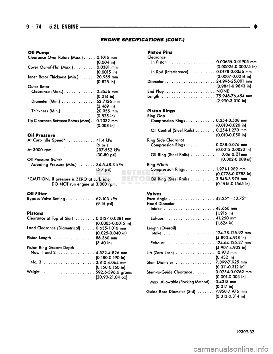
ENGINE
SPECIFICATIONS
(CONT*)
Oil Pump
Clearance Over Rotors (Max.)..... 0.1016 mm (0.004 in)
Cover
Out-of-Flat
(Max.).. ... 0.0381 mm (0.0015 in)
Inner
Rotor
Thickness (Min.) 20.955 mm (0.825 in)
Outer
Rotor
Clearance (Max.)............. 0.3556 mm
(0.014 in)
Diameter
(Min.) 62.7126 mm (2.469 in)
Thickness (Min.) 20.955 mm
(0.825 in)
Tip Clearance
Between
Rotors (Max). . 0.2032 mm
(0.008 in)
Oil Pressure
At Curb
Idle
Speed*
41.4 kPa
(6 psi)
At 3000 rpm 207-552 kPa (30-80 psi)
Oil Pressure
Switch
Actuating
Pressure (Min.) . 34.5-48.3 kPa (5-7 psi)
*CAUTION:
If pressure is
ZERO
at
curb
idle,
DO
NOT run
engine
at 3,000 rpm.
Oil
Filter
Bypass
Valve
Setting
............
62-103 kPa
(9-15 psi)
Pistons
Clearance at Top of
Skirt
.... 0.0127-0.0381 mm (0.0005-0.0015 in)
Land Clearance
(Diametrical)
..... 0.635-1.016 mm (0.025-0.040 in)
Piston
Length
.................
86.360 mm
(3.40 in)
Piston Ring Groove
Depth
Nos.
1 and 2 4.572-4.826 mm (0.180-0.190 in)
No.
3 3.810-4.064 mm (0.150-0.160 in)
Weight
592.6-596.6 grams
(20.90-21.04 oz) Piston Pins
Clearance In Piston . 0.00635-0.01905 mm (0.00025-0.00075 in)
In Rod
(interference)
..........
0.0178-0.0356 mm (0.0007-0.0014 in)
Diameter.
24.996-25.001 mm (0.9841-0.9843 in)
End
Play
NONE
Length
75.946-76.454 mm (2.990-3.010 in)
Piston
Rings
Ring Gap Compression
Rings
. 0.254-0.508 mm (0.010-0.020 in)
Oil
Control
(Steel
Rails) . 0.254-1.270 mm (0.010-0.050 in)
Ring Side Clearance Compression
Rings
0.038-0.076 mm (0.0015-0.0030 in)
Oil Ring
(Steel
Rails)
..........
0.06-0.21 mm (0.002-0.008 in)
Ring
Width
Compression
Rings
1.971-1.989 mm (0.0776-0.0783 in)
Oil Ring
(Steel
Rails) 3.848-3.975 mm (0.1515-0.1565 in)
V®hr©s
Face Angle 43.25° - 43.75°
Head
Diameter
Intake
.....................
48.666 mm (1.916 in)
Exhaust 41.250 mm (1.624 in)
Length
(Overall)
Intake
. 124.28-125.92 mm (4.893-4.918 in)
Exhaust . 124.64-125.27 mm (4.907-4.932 in)
Lift
(Zero
Lash) 10.973 mm (0.432 in)
Stem
Diameter
7.899-7.925 mm (0.311-0.312 in)
Stem-to-Guide
Clearance......... 0.0254-0.0762 mm (0.001-0.003 in)
Max.
Allowable
(Rocking Method). . 0.4318 mm
(0.017 in)
Guide Bore
Diameter
(Std) 7.950-7.976 mm (0.313-0.314 in)
J9309-32
Page 680 of 1502
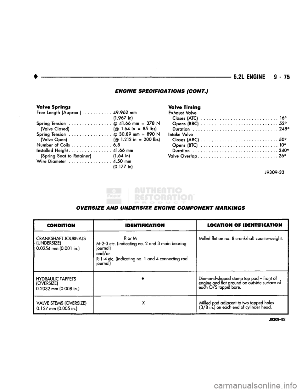
ENGINE SPECIFICATIONS (CONT,)
Valve Springs Free
Length
(Approx.)
49.962
mm
(1.967
in)
Spring Tension
.
@ 41.66 mm
= 378 N
(Valve
Closed)
(@ 1.64 in . 85 lbs)
Spring Tension
.
@ 30.89 mm
=
890
N (Valve Open) (@
1.212
in =
200
lbs)
Number
of
Coils
............... 6.8
Installed Height
41.66
mm (Spring Seat to Retainer)
(1.64
in)
Wire Diameter .
4.50
mm
(0.177
in)
Valve Timing
Exhaust Valve
Closes
(ATC)
16°
Opens
(BBC)
52° Duration
248°
Intake Valve
Closes
(ABC)
50°
Opens
(BTC)
. 10° Duration .
240°
Valve Overlap ... 26°
J9309-33
OVERSIZE AND UNDERSIZE ENGINE COMPONENT MARKINGS
CONDITION
IDENTIFICATION
LOCATION
OF
IDENTIFICATION
CRANKSHAFT JOURNALS (UNDERSIZE)
0.0254 mm (0.001
in.) RorM
M-2-3
etc. (indicating no. 2 and 3 main bearing journal)
and/or
R-l-4 etc.
(indicating no.
1
and 4 connecting rod journal) Milled flat on no. 8 crankshaft counterweight.
HYDRAULIC TAPPETS (OVERSIZE)
0.2032
mm
(0.008
in.) •
Diamond-shaped stamp top pad - front of
engine and flat ground on outside surface of
each O/S tappet bore.
VALVE
STEMS
(OVERSIZE)
0.127 mm (0.005
in.) X
Milled pad adjacent to two tapped holes
(3/8
in.) on each end of cylinder head.
J9309-82
Page 688 of 1502
•
IJL ENGINE 9 - 83
INSPECTION
Inspect all surfaces with a straightedge if there is
any reason to suspect leakage. If out-of-flatness ex
ceeds 0.00075 mm/mm (0.00075 inch/inch) times the span length in inches in any direction, either replace
head or lightly machine the head surface.
FOR EXAMPLE: A 305 mm (12 inch) span is
0.102 mm (0.004 inch) out-of-flat. The allowable out-
of-flat is 305 x 0.00075 (12 x 0.00075) equals 0.23
mm (0.009 inch). This amount of out-of-flat is accept
able.
The cylinder head surface finish should be 1.78-
4.57 microns (70-180 microinches). Inspect push rods. Replace worn or bent rods.
INSTALLATION
(1) Apply Perfect Sealant No.5, or equivalent, to
both sides of the gasket (Fig. 5).
Fig.
5 Sealant Location on Cylinder Head
Gasket
(2) Position the new cylinder head gaskets onto the
cylinder block.
(3) Position the cylinder heads onto head gaskets
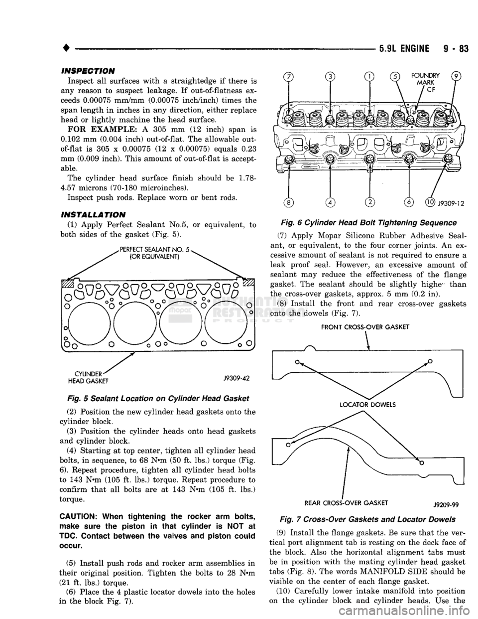
and cylinder block. (4) Starting at top center, tighten all cylinder head
bolts,
in sequence, to 68 N-m (50 ft. lbs.) torque (Fig.
6).
Repeat procedure, tighten all cylinder head bolts
to 143 N-m (105 ft. lbs.) torque. Repeat procedure to confirm that all bolts are at 143 N-m (105 ft. lbs.)
torque.
CAUTION:
When
tightening the rocker arm
bolts,
make
sure
the
piston
in
that
cylinder is NOT at
TDC.
Contact
between the
valves
and
piston
could
occur.
(5) Install push rods and rocker arm assemblies in
their original position. Tighten the bolts to 28 N-m (21 ft. lbs.) torque. (6) Place the 4 plastic locator dowels into the holes
in the block Fig. 7).
Fig.
6 Cylinder Head
Bolt
Tightening
Sequence
(7) Apply Mopar Silicone Rubber Adhesive Seal
ant, or equivalent, to the four corner joints. An ex
cessive amount of sealant is not required to ensure a
leak proof seal. However, an excessive amount of sealant may reduce the effectiveness of the flange
gasket. The sealant should be slightly highe^ than
the cross-over gaskets, approx. 5 mm (0.2 in).
(8) Install the front and rear cross-over gaskets
onto the dowels (Fig. 7).
FRONT
CROSS-OVER GASKET
REAR CROSS-OVER GASKET
J9209-99
Fig.
7
Cross-Over
Gaskets
and Locator
Dowels
(9) Install the flange gaskets. Be sure that the ver
tical port alignment tab is resting on the deck face of
the block. Also the horizontal alignment tabs must
be in position with the mating cylinder head gasket tabs (Fig. 8). The words MANIFOLD SIDE should be
visible on the center of each flange gasket.
(10) Carefully lower intake manifold into position
on the cylinder block and cylinder heads. Use the
Page 691 of 1502
9
• 86 5.9L
ENGINE
•
INTAKE
VALVE
\
MARGIN
/ >
\ACE^
*
STEM
*
VALVE
SPRING
RETAINER
LOCK
GROOVE EXHAUST
VALVE
J9209-127
Fig.
14
intake
and
Exhaust
Waives
REFACING STONE MUST
NOT CUT
VALVE SHROUD Fig.
15 Refacing
Waive
Seats
valve face, contact is satisfactory. If the blue is trans ferred to the top edge of valve face, lower valve seat
with a 15° stone. If the blue is transferred to bottom edge of valve face raise valve seat with a 60° stone.
(4) When seat is properly positioned the width of
intake seats should be
1.016-1.524
mm (0.040-0.060
inch).
The width of the exhaust seats should be
1.524-2.032
mm (0.060-0.080 inch).
VALVE
SPRING
INSPECTION
Whenever valves have been removed for inspection,
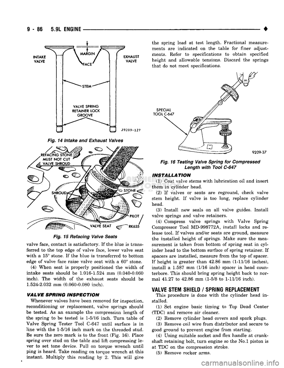
reconditioning or replacement, valve springs should be tested. As an example the compression length of
the spring to be tested is
1-5/16
inch. Turn table of
Valve Spring Tester Tool C-647 until surface is in
line with the
1-5/16
inch mark on the threaded stud. Be sure the zero mark is to the front (Fig. 16). Place spring over stud on the table and lift compressing le
ver to set tone device. Pull on torque wrench until
ping is heard. Take reading on torque wrench at this instant. Multiply this reading by 2. This will give the spring load at test length. Fractional measure
ments are indicated on the table for finer adjust
ments. Refer to specifications to obtain specified
height and allowable tensions. Discard the springs that do not meet specifications.
SPECIAL
TOOL
C-647
9209-37
Fig.
16 Testing
Waive
Spring
for
Compressed
Length
with
Tool
C-647
INSTALLATION
(1) Coat valve stems with lubrication oil and insert
them in cylinder head.
(2) If valves or seats are reground, check valve
stem height. If valve is too long, replace cylinder
head.
(3) Install new seals on all valve guides. Install
valve springs and valve retainers.
(4) Compress valve springs with Valve Spring
Compressor Tool MD-998772A, install locks and re
lease tool. If valves and/or seats are ground, measure
the installed height of springs. Make sure the mea surement is taken from bottom of spring seat in cyl
inder head to the bottom surface of spring retainer. If
spacers are installed, measure from the top of spacer.
If height is greater than 42.86 mm (1-11/16 inches),
install a 1.587 mm (1/16 inch) spacer in head coun-
terbore. This should bring spring height back to nor mal 41.27 to 42.86 mm (1-5/8 to
1-11/16
inch).
¥AL¥E
STEM SHIELD
/
SPRING REPLACEMENT
This procedure is done with the cylinder head in
stalled. (1) Set engine basic timing to Top Dead Center
(TDC) and remove air cleaner. (2) Remove cylinder head covers and spark plugs. (3) Remove coil wire from distributor and secure to
good ground to prevent engine from starting. (4) Using suitable socket and flex handle at crank
shaft retaining bolt, turn engine so the No.l piston is
at TDC on the compression stroke. (5) Remove rocker arms.