1993 DODGE TRUCK change time
[x] Cancel search: change timePage 703 of 1502
(2) Before installing the ring compressor, make
sure the oil ring expander ends are butted and the
rail gaps located properly (Fig. 14).
(3) Immerse the piston head and rings in clean en
gine oil. Slide Piston Ring Compressor Tool C-385
over the piston and tighten with the special wrench (part of Tool C-385). Be
sure position
of
rings does
not change
during this operation.
(4) Install connecting rod bolt protectors on rod
bolts,
the long protector should be installed on the numbered side of the connecting rod. (5) Rotate crankshaft so that the connecting rod
journal is on the center of the cylinder bore. Be sure connecting rod and cylinder bore number are the same. Insert rod and piston into cylinder bore and
guide rod over the crankshaft journal.
(6) Tap the piston down in cylinder bore, using a
hammer handle. At the same time, guide connecting
rod into position on crankshaft journal. (7) The notch or groove on top of piston must be
pointing toward front of engine. The larger chamfer of the connecting rod bore must be Installed toward
crankshaft journal fillet.
(8) Install rod caps. Install nuts on cleaned and
oiled rod bolts and tighten nuts to 61 N*m (45 ft. lbs.)
torque. (9) Install the oil pan.
(10) Install the cylinder head.
(11) Install the engine Into the vehicle.
CRANKSHAFT
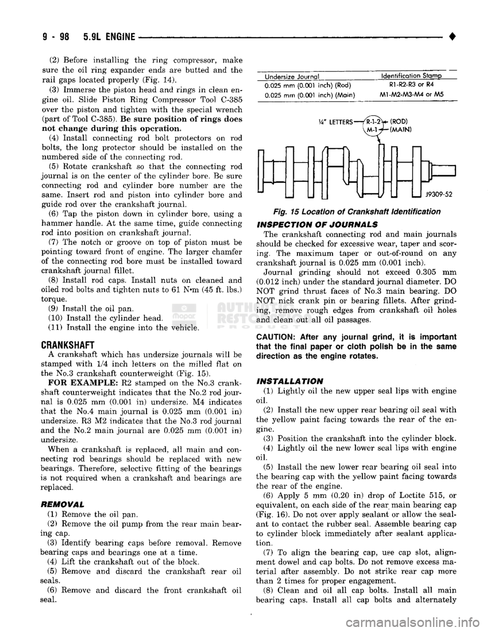
A crankshaft which has undersize journals will be
stamped with 1/4 inch letters on the milled flat on
the No.3 crankshaft counterweight (Fig. 15). FOR EXAMPLE: R2 stamped on the No.3 crank
shaft counterweight indicates that the No.2 rod jour
nal is 0.025 mm (0.001 in) undersize. M4 indicates
that the No.4 main journal is 0.025 mm (0.001 in) undersize. R3 M2 indicates that the No.3 rod journal
and the No.2 main journal are 0.025 mm (0.001 In)
undersize. When a crankshaft is replaced, all main and con
necting rod bearings should be replaced with new
bearings. Therefore, selective fitting of the bearings is not required when a crankshaft and bearings are
replaced.
REMOVAL
(1) Remove the oil pan.
(2) Remove the oil pump from the rear main bear
ing cap.
(3) Identify bearing caps before removal. Remove
bearing caps and bearings one at a time. (4) Lift the crankshaft out of the block.
(5) Remove and discard the crankshaft rear oil
seals.
(6) Remove and discard the front crankshaft oil
seal. Undersize Journal
Identification
Stamp
0.025
mm
(0.001
inch) (Rod)
0.025
mm
(0.001
inch) (Main)
R1-R2-R3
or R4
M1-AA2-M3-AA4
or AA5
V/
LETTERS—/R-l-2>
(ROD)
VM-WHMAIN)
J9309-52
Fig.
15 Location of Crankshaft
identification
INSPECTION
OF
JOURNALS
The crankshaft connecting rod and main journals
should be checked for excessive wear, taper and scor
ing. The maximum taper or out-of-round on any
crankshaft journal is 0.025 mm (0.001 inch).
Journal grinding should not exceed 0.305 mm
(0.012 inch) under the standard journal diameter. DO
NOT grind thrust faces of No.3 main bearing. DO
NOT nick crank pin or bearing fillets. After grind ing, remove rough edges from crankshaft oil holes
and clean out all oil passages.
CAUTION:
After any journal
grind,
it is important
that
the
final
paper or cloth
polish
be in the
same
direction as the engine rotates.
INSTALLATION
(1) Lightly oil the new upper seal lips with engine
oil.
(2) Install the new upper rear bearing oil seal with
the yellow paint facing towards the rear of the en
gine.
(3) Position the crankshaft into the cylinder block.
(4) Lightly oil the new lower seal lips with engine
oil.
(5) Install the new lower rear bearing oil seal into
the bearing cap with the yellow paint facing towards the rear of the engine. (6) Apply 5 mm (0.20 in) drop of Loctite 515, or
equivalent, on each side of the rear main bearing cap (Fig. 16). Do not over apply sealant or allow the seal
ant to contact the rubber seal. Assemble bearing cap
to cylinder block immediately after sealant applica
tion.
(7) To align the bearing cap, use cap slot, align
ment dowel and cap bolts. Do not remove excess ma
terial after assembly. Do not strike rear cap more
than 2 times for proper engagement.
(8) Clean and oil all cap bolts. Install all main
bearing caps. Install all cap bolts and alternately
Page 704 of 1502
•
5.9L ENGINE
9 - 99
BEARING
CAP
J9309-72
Fig.
16 Sealant Application to Bearing Cap tighten to 115 N-m (85 ft. lbs.) torque.
(9) Install oil pump.
(10) Apply Mopar Silicone Rubber Adhesive Seal
ant, or equivalent, at bearing cap to block joint to
provide cap to block and oil pan sealing (Fig. 17). Ap
ply enough sealant until a small amount is squeezed out. Withdraw nozzle and wipe excess sealant off the
oil pan seal groove. (11) Install new front crankshaft oil seal. (12) Immediately install the oil pan.
MOPAR SILICONE SEALANT
RUBBER
ADHESIVE APPLIED
Fig.
17
Apply
Sealant to Bearing Cap to
Block
Joint
CRANKSHAFT
MAIN BEARINGS
Bearing caps are not interchangeable and should
be marked at removal to ensure correct assembly. Upper and lower bearing halves are NOT inter
changeable. Lower main bearing halves of No.2 and
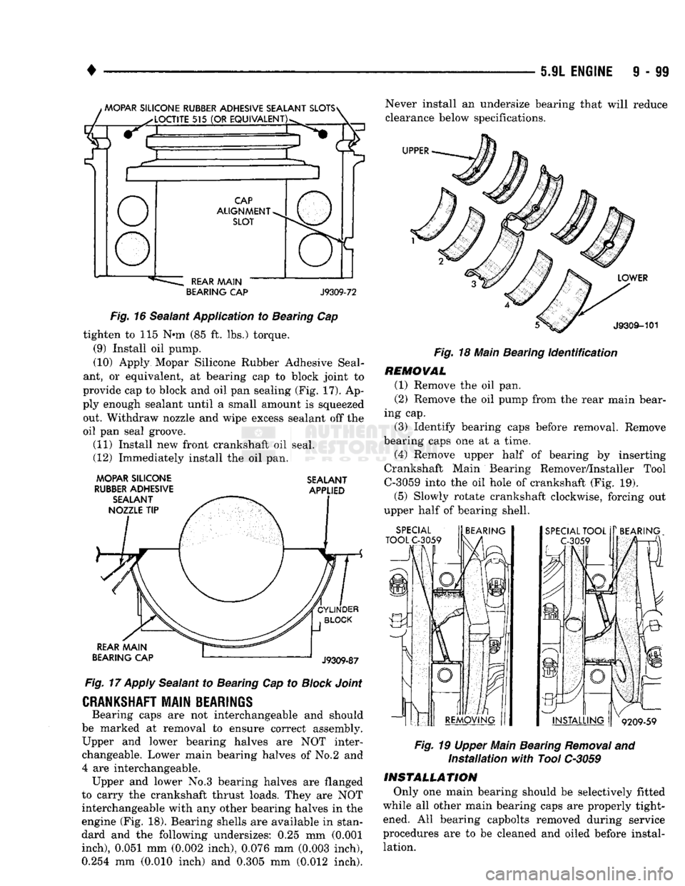
4 are interchangeable. Upper and lower No.3 bearing halves are flanged
to carry the crankshaft thrust loads. They are NOT interchangeable with any other bearing halves in the
engine (Fig. 18). Bearing shells are available in stan
dard and the following undersizes: 0.25 mm (0.001
inch),
0.051 mm (0.002 inch), 0.076 mm (0.003 inch), 0.254 mm (0.010 inch) and 0.305 mm (0.012 inch). Never install an undersize bearing that will reduce
clearance below specifications.
Fig.
18 Main Bearing
Identification
REMOVAL (1) Remove the oil pan.
(2) Remove the oil pump from the rear main bear
ing cap. (3) Identify bearing caps before removal. Remove
bearing caps one at a time.
(4) Remove upper half of bearing by inserting
Crankshaft Main Bearing Remover/Installer Tool
C-3059 into the oil hole of crankshaft (Fig. 19).
(5) Slowly rotate crankshaft clockwise, forcing out
upper half of bearing shell.
Fig.
19 Upper Main Bearing
Removal
and
Installation
with
Tool C-3059
INSTALLATION
Only one main bearing should be selectively fitted
while all other main bearing caps are properly tight ened. All bearing capbolts removed during service
procedures are to be cleaned and oiled before instal lation.
Page 791 of 1502
13 - 4
FRAME
AND
BUMPERS
• • Coil — The electrical component that retracts the
cartridge solenoid.
With power applied, the solenoid retracts and pulls
the poppet valve into the OPEN position.
When power is turned off, the spring forces the so
lenoid back to its normal, CLOSED position.
SOLENOID
VALVE
A The solenoid valve A cartridge contains a poppet
valve. This valve is normally de-energized in the CLOSED position. When closed, the valve retains
pressure in the lift cylinder. When it is energized (valve opened), it allows the fluid to flow from the
lift cylinder back to the reservoir. This enables the
plow blade to lower via gravity.
Solenoid valve A is designed to remain energized
(valve open) during plowing to provide a floating
blade position. This ensures that the plow blade is guided up-down by the surface deviations.
SOLENOID
VALVE
B The solenoid valve B cartridge contains a spool
valve. This valve is normally in the de-energized CLOSED position. This allows the fluid to flow to the
C solenoid. In the energized OPEN position, the fluid
is diverted to the lift cylinder. This causes the plow
blade to be raised.
SOLENOID
VALVE
C The solenoid valve C cartridge contains a spool
valve that is normally in the de-energized CLOSED
position. This allows the fluid to flow to the right- side power angling cylinder. This angles the blade to
the left. At the same time, it allows the fluid from
the retracting left-side power angling cylinder to re
turn to the pump reservoir. Energizing the solenoid valve will route fluid to
the left side angling cylinder. This angles the plow
blade to the right. Also, the fluid is forced from the
retracting right side cylinder. It flows through the C cartridge valve and returns to the pump reservoir.
MECHANICAL HYDRAULIC VALVES The mechanical hydraulic valves all have the same
function: they control the direction of the hydraulic
fluid flow.
CHECK
VALVES
Check valves allow fluid to flow freely in one direc
tion while preventing fluid from flowing in the oppo site direction.
A pump check valve is used to prevent fluid from
leaking back through the pump to the reservoir.
Two additional check valves are necessary because
solenoid valves B and C have some leakage.
One check valve is located between solenoid valve
B and the lift cylinder. It prevents fluid in the lift cylinder from leaking back through solenoid valve B.
If fluid leaks back, it could angle the blade to the
left. This would force fluid through solenoid valve C into the right side cylinder.
The other check valve is located between valve B
and valve C. It prevents fluid from being forced
through solenoid valve B.
PILOT CHECK VALVE
A pilot check valve has a piston in addition to a
ball seat and spring. A pilot check valve is located
between solenoid valve C and the reservoir. It has two functions:
• Prevents the hydraulic fluid in either angling cylinder from leaking back to the reservoir.
• Allows the hydraulic fluid from a retracting an
gling cylinder to return to the reservoir. The valve action is done by fluid moving the pis
ton, which forces the check ball off its seat.
CROSSOVER
RELIEF VALVE
This valve protects against damage by a sudden
impact against the end of the blade. This will cause
high hydraulic pressure to accumulate in one of the angling cylinders. The hydraulic pressure increases enough to open
the crossover relief valve. The valve allows the
highly pressurized hydraulic fluid to flow to the other cylinder. This cushions the impact and changes
the position of the blade.
SYSTEM OPERATION Refer to Figures 2 through 5 for voltage application
and hydraulic fluid flow for each snow plow function.
Each figure shows the components that are actuated
for each function.
SNOW
PLOW WIRING DIAGRAMS
Refer to Figures 6, 7 and 8 for wiring diagrams.
Refer to Specifications chart at the end of this
group.
SNOW PLOW MALFUNCTION DIAGNOSIS
AND
TESTS
Refer to the charts and illustrations for proper di
agnosis.
SOLENOID VALVE COIL FUNCTIONAL TEST Test the coils for proper operation, according to the
following procedure. (1) Hold a screwdriver blade about 1/8 inch above
the nut on the coil to be tested. (2) Have a helper operate the control switch that
energizes the applicable coil.
CAUTION:
Do not connect an ohmmeter to a coil
when it is
applied.
This
can
cause
internal
damage
to the ohmmeter.
(3) If the coil is working, the electromagnetic ac
tion will pull the screwdriver down to the retaining nut. If this does not occur, use an ohmmeter to check
the coil for continuity.
Page 851 of 1502
14
- 32
FUEL SYSTEM
•
BATTERY VOLTAGE—PCM
INPUT
The battery voltage input provides power
to the
powertrain control module (PCM).
It
also informs
the
PCM what voltage level
is
supplied
to the
ignition
coil
and
fuel injectors. If battery voltage
is low, the PCM
will increase injec
tor pulse width (period
of
time that
the
injector
is
ener
gized).
This
is
done
to
compensate
for the
reduced flow
through injector caused
by the
lowered voltage.
BRAKE
SWITCH-PCM
INPUT
When
the
brake light switch
is
activated,
the
pow
ertrain control module
(PCM)
receives
an
input indi
cating that
the
brakes
are
being applied. After
receiving this input,
the PCM
maintains idle speed
to
a
scheduled
rpm
through control
of the
idle
air
control
(IAC)
motor.
The
brake switch input
is
also
used
to
operate
the
speed control system.
CAMSHAFT POSITION SENSOR—PCM
INPUT
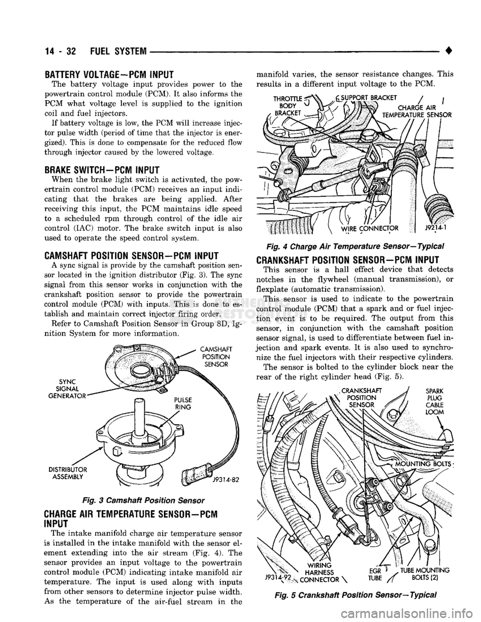
A sync signal
is
provide
by the
camshaft position sen
sor located
in the
ignition distributor
(Fig.
3).
The
sync
signal from this sensor works
in
conjunction with
the
crankshaft position sensor
to
provide
the
powertrain
control module
(PCM)
with inputs. This
is
done
to es
tablish
and
maintain correct injector firing order. Refer
to
Camshaft Position Sensor
in
Group
8D, Ig
nition System
for
more information.
Fig.
3
Camshaft Position
Sensor
CHARGE AIR TEMPERATURE SENSOR-PCM
INPUT
The intake manifold charge
air
temperature sensor
is installed
in the
intake manifold with
the
sensor
el
ement extending into
the air
stream
(Fig. 4). The
sensor provides
an
input voltage
to the
powertrain control module
(PCM)
indicating intake manifold
air
temperature.
The
input
is
used along with inputs from other sensors
to
determine injector pulse width. As
the
temperature
of the
air-fuel stream
in the
manifold varies,
the
sensor resistance changes. This
results
in a
different input voltage
to the PCM.
Fig.
4
Charge
Air
Temperature
Sensor—Typical
CRANKSHAFT POSITION SENSOR-PCM INPUT
This sensor
is a
hall effect device that detects
notches
in the
flywheel (manual transmission),
or
flexplate (automatic transmission). This sensor
is
used
to
indicate
to the
powertrain
control module
(PCM)
that
a
spark
and or
fuel injec
tion event
is to be
required.
The
output from this sensor,
in
conjunction with
the
camshaft position
sensor signal,
is
used
to
differentiate between fuel
in
jection
and
spark events.
It is
also used
to
synchro nize
the
fuel injectors with their respective cylinders. The sensor
is
bolted
to the
cylinder block near
the
rear
of the
right cylinder head
(Fig. 5).
Fig.
5
Crankshaft Position Sensor—Typical
Page 852 of 1502
•
FUEL SYSTEM
14 - 33 Refer to Group 8D, Ignition System for more crank
shaft position sensor information. The engine will not operate if the PCM does not re
ceive a crankshaft position sensor input.
ENGINE
COOLANT TEMPERATURE SENSOR-PCM
INPUT
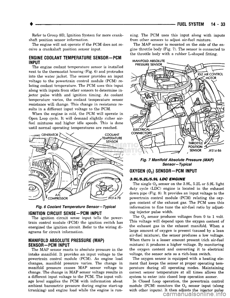
The engine coolant temperature sensor is installed
next to the thermostat housing (Fig. 6) and protrudes
into the water jacket. The sensor provides an input
voltage to the powertrain control module (PCM) re
lating coolant temperature. The PCM uses this input
along with inputs from other sensors to determine in
jector pulse width and ignition timing. As coolant temperature varies, the coolant temperature sensor
resistance will change. This change in resistance results in a different input voltage to the PCM. When the engine is cold, the PCM will operate in
Open Loop cycle. It will demand slightly richer air-
fuel mixtures and higher idle speeds. This is done until normal operating temperatures are reached.
Fig.
6 Coolant
Temperature
Sensor—
Typical
IGNITION CIRCUIT
SENSE-PCM
INPUT
The ignition circuit sense input tells the power-
train control module (PCM) the ignition switch has
energized the ignition circuit. Refer to the wiring di
agrams for circuit information.
MANIFOLD ABSOLUTE
PRESSURE
(MAP)
SENSOR-PCM
INPUT
The MAP sensor reacts to absolute pressure in the
intake manifold. It provides an input voltage to the
powertrain control module (PCM). As engine load changes, manifold pressure varies. The change in
manifold pressure causes MAP sensor voltage to
change. The change in MAP sensor voltage results in a different input voltage to the PCM. The input volt
age level supplies the PCM with information about
ambient barometric pressure during engine start-up (cranking) and engine load while the engine is run ning. The PCM uses this input along with inputs
from other sensors to adjust air-fuel mixture.
The MAP sensor is mounted on the side of the en
gine throttle body (Fig. 7). The sensor is connected to
the throttle body with a rubber L-shaped fitting.
MANIFOLD
ABSOLUTE
Fig.
7 Manifold
Absolute
Pressure
(MAP)
Sensor—
Typical
OXYGEN
(02)
SENSOR—PCM
INPUT
3.9L/5.2L/S»9L
LDC
ENGINE
The single 02 sensor on the 3.9L, 5.2L or 5.9L light
duty cycle (LDC) engine is located in the exhaust
down pipe (Fig. 8). It provides an input voltage to the
powertrain control module (PCM) relating the oxy
gen content of the exhaust gas. The PCM uses this
information to fine tune the air-fuel ratio by adjust ing injector pulse width.
The 02 sensor produces voltages from 0 to 1 volt.
This voltage will depend upon the oxygen content of
the exhaust gas in the exhaust manifold. When a large amount of oxygen is present (caused by a lean
air-fuel mixture), the sensor produces a low voltage.
When there is a lesser amount present (rich air-fuel
mixture) it produces a higher voltage. By monitoring
the oxygen content and converting it to electrical
voltage, the sensor acts as a rich-lean switch.
The oxygen sensor is equipped with a heating ele
ment that keeps the sensor at proper operating tem
perature during all operating modes. Maintaining
correct sensor temperature at all times allows the system to enter into closed loop operation sooner. In Closed Loop operation, the powertrain control
module (PCM) monitors the 02 sensor input (along
with other inputs). It then adjusts the injector pulse
Page 875 of 1502
14
- 56
FUEL
SYSTEM
• (5) Move the switch to the HIGH position. The en
gine speed should increase. Move the switch to the
LOW position. The engine speed should decrease.
(a) If the engine speed changes while using the
exerciser tool, the IAC motor is functioning prop
erly. Disconnect the exerciser tool and connect the
IAC stepper motor wire connector to the stepper motor.
(b) If the engine speed does not change, turn the
ignition OFF and proceed to step (6). Do not discon
nect exerciser from the IAC stepper motor.
(6) Remove the IAC stepper motor from the throt
tle body.
CAUTION:
When checking IAC motor operation with
the motor removed from
the
throttle
body,
do not
extend
the
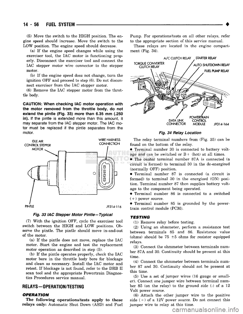
pintle (Fig.
33)
more than
6.35 mm (.250
in).
If the pintle is
extended more than
this
amount,
it
may
separate
from
the
IAC stepper
motor.
The
IAC
mo
tor
must
be
replaced
if the pintle
separates
from
the
motor.
WIRE HARNESS
PINTLE
J9314-116
Fig.
33 IAC Stepper Motor Pintle—Typical (7) With the ignition OFF, cycle the exerciser tool
switch between the HIGH and LOW positions. Ob
serve the pintle. The pintle should move in-and-out
of the motor.
(a) If the pintle does not move, replace the IAC
motor. Start the engine and test the replacement
motor operation as described in step (5). (b) If the pintle operates properly, check the IAC
motor bore in the throttle body bore for blockage and clean as necessary. Install the IAC motor and
retest. If blockage is not found, refer to the DRB II scan tool and the appropriate Powertrain Diagnos
tics Procedures service manual.
RELAYS—OPERATION/TESTING
OPERATION
The following operations/tests apply to these
relays only: Automatic Shut Down (ASD) and Fuel Pump. For operations/tests on all other relays, refer
to the appropriate section of this service manual.
These relays are located in the engine compart
ment (Fig. 34).
DATA LINK CONTROL
CONNECTOR MODULE
J9314-164
Fig.
34 Relay Location The relay terminal numbers from (Fig. 35) can be
found on the bottom of the relay. • Terminal number 30 is connected to battery volt
age and can be switched or B+ (hot) at all times.
• The center terminal number 87A is connected (a
circuit is formed) to terminal 30 in the de-energized (normally OFF) position.
• Terminal number 87 is connected (a circuit is
formed) to terminal 30 in the energized (ON) posi
tion. Terminal number 87 then supplies battery volt age to the component being operated.
• Terminal number 86 is connected to a switched ( +
)
power source.
• Terminal number 85 is grounded by the power-
train control module (PCM).
TESTING
(1) Remove relay before testing. (2) Using an ohmmeter, perform a resistance test
between terminals 85 and 86. Resistance value (ohms) should be 75 ±5 ohms for resistor equipped
relays.
(3) Connect the ohmmeter between terminals num
ber 87A and 30. Continuity should be present at this
time.
(4) Connect the ohmmeter between terminals num
ber 87 and 30. Continuity should not be present at
this time.
(5) Use a set of jumper wires (16 gauge or small
er).
Connect one jumper wire between terminal num
ber 85 (on the relay) to the ground side (-) of a 12 Volt power source. (6) Attach the other jumper wire to the positive
side ( +
)
of a 12V power source. Do not connect this
jumper wire to relay at this time.
Page 900 of 1502
•
FUEL
SYSTEM
14-81
AIR
CONDITIONING
(A/C)
CLUTCH RELAY—PCM
OUTPUT
The PCM activates the A/C compressor through the
A/C clutch relay. The PCM regulates A/C compressor
operation by switching the ground circuit for the A/C
clutch relay on and off. The relay is located in the engine compartment (Fig. 3). By switching the ground path for the relay on and
off, the PCM is able to cycle the A/C compressor
clutch. This is based on changes in engine operating
conditions. If, during A/C operation, the PCM senses
a low idle speed, it will de-energize the relay. This
prevents A/C clutch engagement. The relay will re main de-energized until the idle speed increases.
GENERATOR
FIELD-PCM
OUTPUT
The PCM regulates the charging system voltage
within a range of 12.9 to 15.0 volts. It will control
ASD relay operation. The input (through the PCM)
for the ASD relay comes from the engine speed sen sor. When engine running speed is above 384 rpm, a
signal is sent from the PCM to engage the ASD re
lay. This supplies the necessary generator field wind
ing control. When rpm drops below 320, the signal to
the ASD relay is stopped. Refer to Group 8A, for charging system information.
AIR INTAKE HEATER RELAYS-PCM
OUTPUT
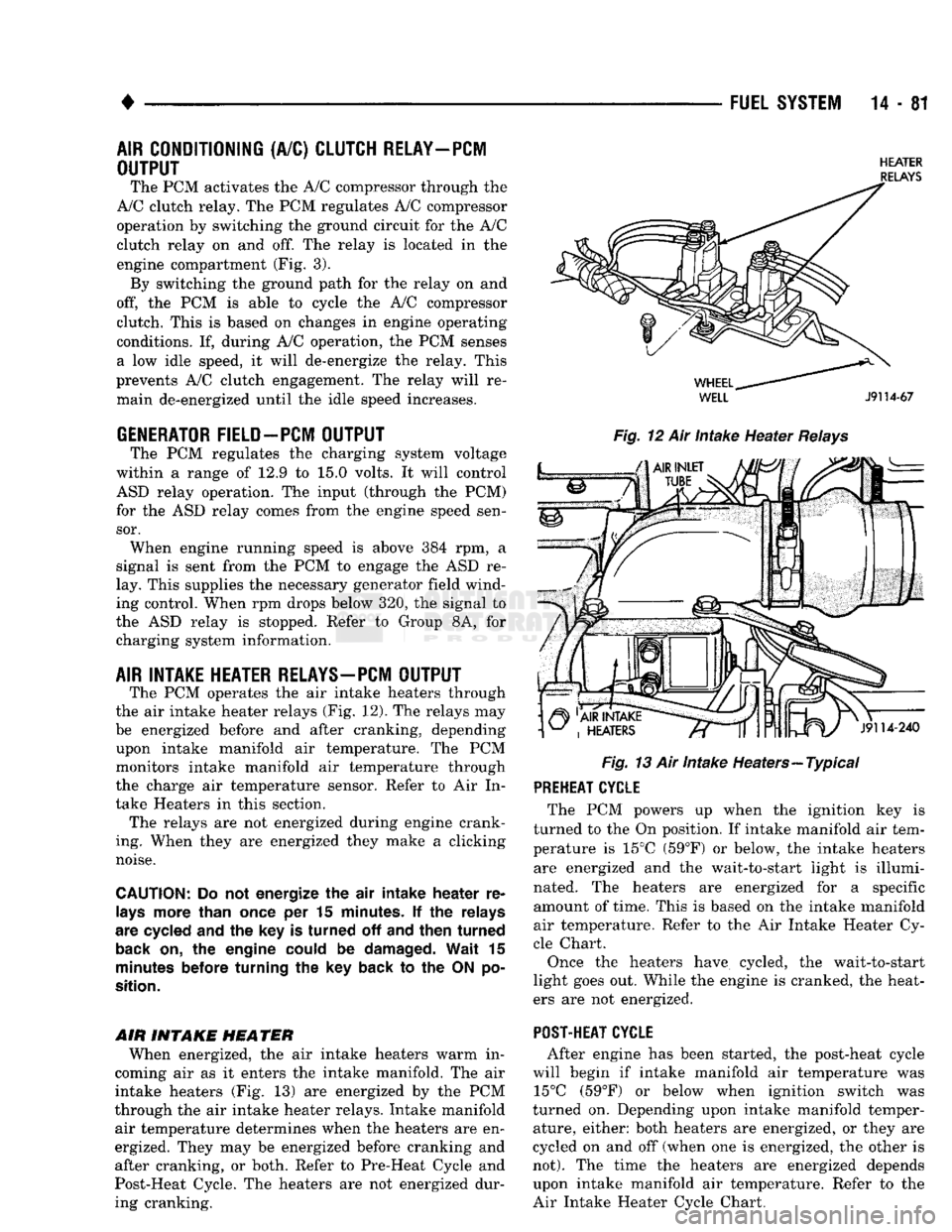
The PCM operates the air intake heaters through
the air intake heater relays (Fig. 12). The relays may
be energized before and after cranking, depending upon intake manifold air temperature. The PCM
monitors intake manifold air temperature through
the charge air temperature sensor. Refer to Air In
take Heaters in this section. The relays are not energized during engine crank
ing. When they are energized they make a clicking
noise.
CAUTION:
Do not energize the air intake heater re
lays
more than
once
per 15
minutes.
If the relays
are
cycled
and the key is turned off and then turned
back
on, the engine
could
be
damaged.
Wait 15
minutes
before
turning the key back to the ON po
sition.
AIR INTAKE
HEATER
When energized, the air intake heaters warm in
coming air as it enters the intake manifold. The air
intake heaters (Fig. 13) are energized by the PCM
through the air intake heater relays. Intake manifold air temperature determines when the heaters are en
ergized. They may be energized before cranking and
after cranking, or both. Refer to Pre-Heat Cycle and
Post-Heat Cycle. The heaters are not energized dur ing cranking.
HEATER
RELAYS
WELL
J9114-67
Fig.
12 Air Intake Heater
Relays
Fig.
13 Air Intake Heaters—Typical PREHEAT CYCLE
The PCM powers up when the ignition key is
turned to the On position. If intake manifold air tem
perature is 15°C (59°F) or below, the intake heaters are energized and the wait-to-start light is illumi
nated. The heaters are energized for a specific amount of time. This is based on the intake manifold
air temperature. Refer to the Air Intake Heater Cy
cle Chart.
Once the heaters have cycled, the wait-to-start
light goes out. While the engine is cranked, the heat
ers are not energized.
POST-HEAT CYCLE
After engine has been started, the post-heat cycle
will begin if intake manifold air temperature was 15°C (59°F) or below when ignition switch was
turned on. Depending upon intake manifold temper ature, either: both heaters are energized, or they are
cycled on and off (when one is energized, the other is
not).
The time the heaters are energized depends upon intake manifold air temperature. Refer to the
Air Intake Heater Cycle Chart.
Page 911 of 1502
14-92
FUEL
SYSTEM
• A broken injection pump timing mechanism spring
will cause the timing to be fully advanced resulting
in torque loss, a fuel knock and possible engine over
heating.
An improperly operating KSB (cold start) solenoid
will cause white smoke during engine warm-up. The
KSB solenoid is not serviceable.
A defective or non-adjustable fuel injection pump
can cause starting problems or prevent the engine
from revving up. It can also cause:
• Engine surge at idle • Rough idle (warm engine)
• Engine miss under load
• Low power
• Excessive fuel consumption
• Poor performance
• Low power
• Black smoke from the exhaust • Blue or white fog like exhaust
• Incorrect idle or maximum speed A worn fuel injection pump plunger can effect fuel
pressure and the amount of fuel injected. This results in reduced engine power. In most cases, if the injec
tion pump is delivering fuel from one outlet, it will deliver fuel from all outlets. If the internal plunger is defective, the fuel injection pump must be re
placed.
Engine power is also effected by the governor set
ting and performance. Do not attempt to adjust the governor. If the governor seals on the external adjustment screw are broken, the fuel rate may
be out of adjustment. The warranty of the injec tion pump and the engine may be void if the
seals have been tampered with or removed.
FUEL
INJECTORS
A leaking fuel injector can cause fuel knock, poor
performance, black smoke, poor fuel economy and
rough engine idle. If the fuel injector needle valve
does not operate properly, the engine may misfire and produce low power. A leak in the injection pump-to-injector high pres
sure fuel line can cause many of the same symptoms as a malfunctioning injector. Inspect for a leak in the
high pressure lines before checking for a malfunc
tioning fuel injector.
WARNING:
THE
INJECTION PUMP SUPPLIES HIGH
PRESSURE
FUEL
OF
APPROXIMATELY
59,000
KPA
(8,000
PSI) TO
EACH INDIVIDUAL INJECTOR
THROUGH THE HIGH
PRESSURE
LINES. FUEL UN
DER
THIS AMOUNT
OF
PRESSURE
CAN
PENE
TRATE THE SKIN AND CAUSE PERSONAL INJURY,
WEAR
SAFETY GOGGLES
AND
ADEQUATE PRO
TECTIVE CLOTHING. AVOID CONTACT
WITH
FUEL
SPRAY
WHEN BLEEDING HIGH
PRESSURE
FUEL
LINES.
WARNING:
DO NOT
BLEED
AIR
FROM
THE
FUEL
SYSTEM
OF A
HOT ENGINE.
DO
NOT ALLOW FUEL
TO SPRAY ONTO THE EXHAUST MANIFOLD WHEN
BLEEDING
AIR
FROM THE FUEL SYSTEM.
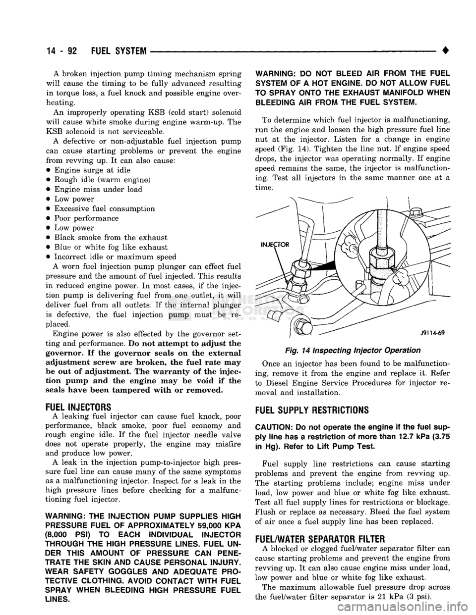
To determine which fuel injector is malfunctioning,
run the engine and loosen the high pressure fuel line nut at the injector. Listen for a change in engine
speed (Fig. 14). Tighten the line nut. If engine speed
drops,
the injector was operating normally. If engine
speed remains the same, the injector is malfunction
ing. Test all injectors in the same manner one at a
time.
Fig. 14
Inspecting
Injector Operation
Once an injector has been found to be malfunction
ing, remove it from the engine and replace it. Refer
to Diesel Engine Service Procedures for injector re moval and installation.
FUEL
SUPPLY
RESTRICTIONS
CAUTION:
Do not
operate
the
engine
if the
fuel
sup ply
line
has
a
restriction
of
more
than
12.7
kPa
(3.75
in
Hg).
Refer
to
Lift
Pump
Test.
Fuel supply line restrictions can cause starting
problems and prevent the engine from revving up.
The starting problems include; engine miss under load, low power and blue or white fog like exhaust.
Test all fuel supply lines for restrictions or blockage.
Flush or replace as necessary. Bleed the fuel system
of air once a fuel supply line has been replaced.
FUEL/WATER
SEPARATOR
FILTER
A blocked or clogged fuel/water separator filter can
cause starting problems and prevent the engine from
revving up. It can also cause engine miss under load,
low power and blue or white fog like exhaust. The maximum allowable fuel pressure drop across
the fuel/water filter separator is 21 kPa (3 psi).