1993 DODGE TRUCK TORQUE CONVERTER
[x] Cancel search: TORQUE CONVERTERPage 43 of 1502
0
- 24
LUBRICATION
AND
MAINTENANCE
•
CAUTION:
Do not
overfill
the
transmission.
(9) Adjust
the
level
of the ATF
accordingly.
It
is
important
to use the
correct fluid
in an
automatic transmission. MOPAR®ATF PLUS
(ATF Type
7176)
should
be
used. Dexron®
II
ATF
can be
used
if the
recommended fluid
is not
available,
(10) Insert
the
dipstick into
the
tube.
DRAIN, FILTER CHANGE, BAND ADJUSTMENT AND REFILL
The chart below lists
the
intervals
at
which
the
transmission should
be
serviced. Also, refer
to the
Fluid Capacities chart
for
fill capacity.
AUTOMATIC TRANSMISSION SERVICE
IN-
TERVALS
Normal
Usage
Light
Duty
Cycle
60 000
km
37,500
miles
Heavy
Duty
Cycle
38
000 km 24,000
miles
Severe
Usage
19 000 km 12,000
miles
J9100-19
It
is
very important
to use the
correct fluid
in
an automatic transmission. MOPAR®ATF PLUS
(ATF Type
7176)
should
be
used.
An
equivalent
Dexron®
II ATF
could
be
used only
if the
recom
mended fluid
is not
available.
The torque converter does
not
have
a
drain plug.
No attempt should
be
made
to
drain
the
converter.
Refer
to
Group
21
—Transmissions
for
transmission
drain
and
refill procedures.
TRANSFER
CASE
(4WD
VEHICLES)
INSPECTION The NP205
and
NP241 transfer cases fluid level
should
be
checked whenever maintenance
is
neces
sary under
the
vehicle.
FLUID
LEVEL
The vehicle must
be
level when
the
fluid level
is checked.
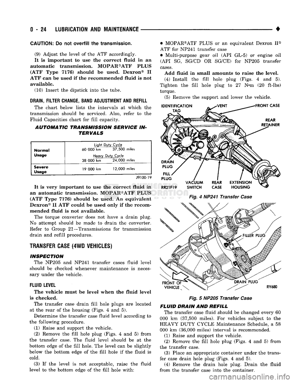
The transfer case drain fill hole plugs
are
located
at
the
rear
of the
housing (Figs.
4 and 5).
Determine
the
transfer case fluid level according
to
the following procedure.
(1) Raise
and
support
the
vehicle.
(2) Remove
the
fill hole plug (Figs.
4 and 5)
from
the transfer case.
The
fluid level should
be at the
bottom edge
of the
fill hole.
The
level
can be
slightly
below
the
bottom edge
of the
fill hole
if the
fluid
is
cold.
(3)
If the
level
is not
acceptable, raise
the
fluid
level
to the
bottom edge
of the
fill hole with: • MOPAR®ATF PLUS
or an
equivalent Dexron
II®
ATF
for
NP241 transfer case
• Multi-purpose gear
oil (API GL-5) or
engine
oil
(API
SG,
SG/CD
OR
SG/CE)
for
NP205 transfer
cases.
Add fluid
in
small amounts
to
raise
the
level. (4) Install
the
fill hole plug (Figs.
4 and 5).
Tighten
the
fill hole plug
to 27 N-m (20
ft-lbs) torque.
(5) Remove
the
support
and
lower
the
vehicle.
Fig.
4
HP241 Transfer
Case
Fig.
5
NP205 Transfer
Case
FLUID DRAIN
AND
REFILL The transfer case fluid should
be
changed every
60
000
km
(37,500 miles).
For
vehicles subject
to the
HEAVY DUTY CYCLE Maintenance Schedule,
a 58
000
km
(36,000 miles) interval
is
recommended.
(1) Raise
and
support
the
vehicle.
(2) Remove
the
fill hole plug (Figs.
4 and 5)
from
the transfer case. (3) Place
an
appropriate container under
the
trans
fer case drain hole plug (Figs.
4 and 5).
(4) Remove
the
drain hole plug. Drain
the
fluid
from
the
transfer case into
the
container.
Page 191 of 1502
5
- 4
BRAKES
• (3) During road test, make normal and firm brake
stops in 25-40 mph (40-64 Km/h) range. Note faulty
brake operation such as pull, grab, drag, noise, low
pedal, etc.
(4) Inspect suspect brake components and refer to
problem diagnosis information for causes of various
brake conditions.
COMPONENT
INSPECTION
Fluid leak points and dragging brake units can usu
ally be located without removing any components. The
area around a leak point will be wet with fluid. The
components at a dragging brake unit (wheel, tire, rotor)
will be quite warm or hot to the touch.
Other brake problem conditions will require compo
nent removal for proper inspection. Raise the vehicle and remove the necessary wheels for better visual ac
cess.
DIAGNOSING BRAKE
PROBLEMS
PEDAL FALLS
AWAY
A
brake pedal that falls away under steady foot
pressure is the result of a system leak. The leak
point could be at a brakeline, fitting, hose, or caliper. Internal leakage in the master cylinder caused by
worn or damaged piston cups, may also be the prob lem cause.
If leakage is severe, fluid will be evident at or around
the leaking component. However, internal leakage in
the master cylinder may not be physically evident. Re fer to the cylinder test procedure in this section.
LOW PEDAL
If a low pedal is experienced, pump the pedal sev
eral times. If the pedal comes back up, worn lining
and worn rotors or drums are the likely causes.
A decrease in fluid level in the master cylinder res
ervoirs may only be the result of normal lining wear.
Fluid level can be expected to decrease in proportion to wear. It is a result of the outward movement of
caliper and wheel cylinder pistons to compensate for
normal wear. Top off the reservoir fluid level and
check brake operation to verify proper brake action.
SPONGY PEDAL. A spongy pedal is most often caused by air in the sys
tem. Thin brake drums or substandard brake lines and
hoses can also cause a spongy pedal. The proper course
of action is to bleed the system and replace thin drums and suspect quality brake lines and hoses.
HARD PEDAL
OR
HIGH
PEDAL
EFFORT
A hard pedal or high pedal effort may be due to
lining that is water soaked, contaminated, glazed, or
badly worn. The power booster or check valve could also be faulty. On diesel engine models, high pedal effort may be
the result of a low vacuum condition. If the booster and check valve are OK, the problem may be related
to a vacuum pump hose, hose connection, hose fit
ting, pump diaphragm, or drive gear. Vacuum pump output can be checked with a standard vacuum
gauge. Vacuum output should range from 8.5 to 25 inches vacuum. If vacuum pump output is within
limits,
check the power booster and check valve as
described in this section.
BRAKE DRAG
Brake drag occurs when the lining is in constant
contact with the rotor or drum. Drag can occur at
one wheel, all wheels, fronts only, or rears only. It is a product of incomplete brakeshoe release. Drag can
be minor or severe enough to overheat the linings,
rotors and drums.
Brake drag can also effect fuel economy. If undetec
ted, minor brake drag can be misdiagnosed as an en gine or transmission/torque converter problem.
Minor drag will usually cause slight surface charring
of the lining. It can also generate hard spots in rotors and drums from the overheat-cool down process. In most
cases,
the rotors, drums, wheels and tires are quite
warm to the touch after the vehicle is stopped.
Severe drag can char the brake lining all the way
through. It can also distort and score rotors and drums to the point of replacement. The wheels, tires and brake components will be extremely hot. In se
vere cases, the lining may generate smoke as it chars
from overheating.
Some common causes of brake drag are:
• seized or improperly adjusted parking brake cables
• loose/worn wheel bearing
• seized caliper or wheel cylinder piston
• caliper binding on corroded bushings or rusted
slide surfaces
• loose caliper mounting bracket
• drum brakeshoes binding on worn or damaged sup
port plates
• misassembled components. If brake drag occurs at all wheels, the problem may
be related to a blocked master cylinder return port, or faulty power booster that binds and does not release.
BRAKE FADE
Brake fade is a product of overheating caused by
brake drag. However, brake overheating and subse quent fade can also be caused by riding the brake
pedal, making repeated high deceleration stops in a short time span, or constant braking on steep moun
tain roads. Refer to the Brake Drag information in
this section for additional causes.
PEDAL
PULSA
TION
Pedal pulsation is caused by components that are
loose, out of round, or worn beyond tolerance limits.
Page 356 of 1502
•
IGNITION
SYSTEMS
8D - 5
THROTTLE
^
BODY
u
BRACKET
y^SUPPORT
BRACKET
/ |
CHARGE
AIR
ijmmmmk
TEMPERATURE
SENSOR
THROTTLE
BODY
Fig.
9
Sensor
Location—3.9L Engine—Typical
INTAKE MANIFOLD
'b AIR TEMPERATURE
SENSOR
J9314-162
Fig.
10
Sensor
Location—5.2L/5.9L
Engines—Typical
start-up (cranking) and to engine load while the en
gine is running. The PCM uses this input, along with
inputs from other sensors, to adjust air-fuel mixture.
For more information, refer to Group 14, Fuel Sys
tem.
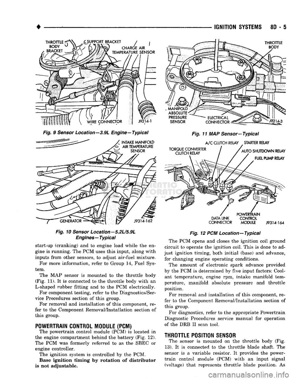
The MAP sensor is mounted to the throttle body
(Fig. 11). It is connected to the throttle body with an
L-shaped rubber fitting and to the PCM electrically. For component testing, refer to the Diagnostics/Ser
vice Procedures section of this group. For removal and installation of this component, re
fer to the Component Removal/Installation section of
this group.
POWERTRAIN CONTROL MODULE
(PCM) The powertrain control module (PCM) is located in
the engine compartment behind the battery (Fig. 12).
The PCM was formerly referred to as the SBEC or engine controller. The ignition system is controlled by the PCM. Base ignition timing by rotation of distributor
is not adjustable.
MANIFOLD
ABSOLUTE
PRESSURE
SENSOR
TORQUE CONVERTER CLUTCH RELAY
ELECTRICAL
Jlp^
CONNECTOR
^gis!—
Fig.
11 MAP Sensor—Typical
A/C
CLUTCH RELAY STARTER RELAY
AUTO
SHUTDOWN RELAY FUEL PUMP RELAY
DATA LINK
CONNECTOR POWERTRAIN
CONTROL
MODULE
J9314-164
Fig.
12 PCM Location—Typical The PCM opens and closes the ignition coil ground
circuit to operate the ignition coil. This is done to ad
just ignition timing, both initial (base) and advance, for changing engine operating conditions.
The amount of electronic spark advance provided
by the PCM is determined by five input factors: Cool ant temperature, engine rpm, intake manifold tem
perature, manifold absolute pressure and throttle
position.
For removal and installation of this component, re
fer to the Component Removal/Installation section of
this group.
For diagnostics, refer to the appropriate Powertrain
Diagnostic Procedures service manual for operation
of the DRB II scan tool.
THROTTLE
POSITION
SENSOR
The sensor is mounted on the throttle body (Fig.
13).
It is connected to the throttle blade shaft. The
sensor is a variable resistor. It provides the power-
train control module (PCM) with an input signal (voltage) that represents throttle blade position. As
Page 369 of 1502
8D
- 18
IGNITION
SYSTEMS
•
COMPONENT REMGWAL/INSTALLATION
INDEX
page
Automatic
Shut Down (ASD) Relay
18
Camshaft
Position
Sensor
, 18
Crankshaft Position
Sensor
18
Distributor
Service
20
Engine
Coolant Temperature
Sensor
20
General
Information
18
Ignition
Coil
21
page
Intake
Manifold Charge
Air
Temperature
Sensor
. 22
Manifold Absolute Pressure (MAP)
Sensor
..... 22
Oxygen
(02)
Sensor
22
Powertrain
Control
Module (PCM)
22
Spark
Plug Secondary Cables
24
Spark
Plugs
23
Throttle
Position
Sensor
(TPS)
24
GENERAL
INFORMATION
This section
of the
group, Component Removal/In
stallation, will discuss
the
removal
and
installation
of ignition system components. For basic ignition system diagnostics
and
service
adjustments, refer
to the
Diagnostics/Service Proce
dures section
of
this group. For system operation
and
component identification,
refer
to the
Component Identification/System Opera
tion section
of
this group.
AUTOMATIC
SHUT DOWN
(ASb)
RELAY
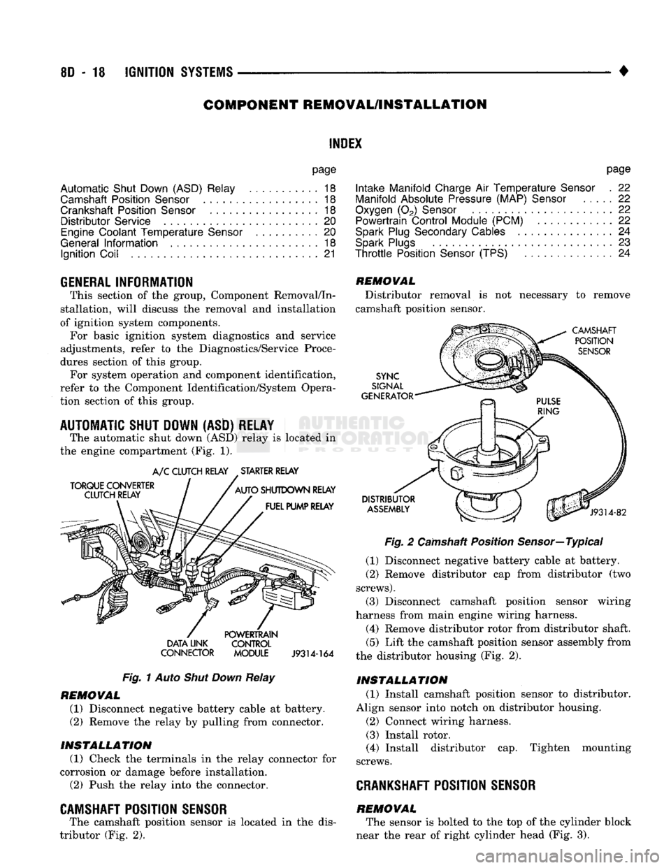
The automatic shut down
(ASD)
relay
is
located
in
the engine compartment
(Fig. 1).
TORQUE CONVERTER
CLUTCH RELAY
A/C
CLUTCH RELAY STARTER RELAY
AUTO
SHUTDOWN RELAY FUEL PUMP RELAY DATA UNK
CONNECTOR POWERTRAIN
CONTROL
MODULE
J9314-164
Fig.
1
Auto
Shut Down
Relay
REMOVAL
(1) Disconnect negative battery cable
at
battery.
(2)
Remove
the
relay
by
pulling from connector.
INSTALLATION
(1) Check
the
terminals
in the
relay connector
for
corrosion
or
damage before installation.
(2)
Push
the
relay into
the
connector.
CAMSHAFT POSITION SENSOR
The camshaft position sensor
is
located
in the
dis
tributor
(Fig. 2).
REMOVAL
Distributor removal
is not
necessary
to
remove
camshaft position sensor.
CAMSHAFT POSITION
SENSOR
SYNC
SIGNAL
GENERATOR
DISTRIBUTOR
ASSEMBLY
J9314-82
Fig.
2
Camshaft Position Sensor—Typical
(1) Disconnect negative battery cable
at
battery.
(2)
Remove distributor
cap
from distributor
(two
screws).
(3) Disconnect camshaft position sensor wiring
harness from main engine wiring harness.
(4) Remove distributor rotor from distributor shaft.
(5)
Lift
the
camshaft position sensor assembly from
the distributor housing
(Fig. 2).
INSTALLATION
(1) Install camshaft position sensor
to
distributor.
Align sensor into notch
on
distributor housing.
(2)
Connect wiring harness.
(3) Install rotor.
(4) Install distributor
cap.
Tighten mounting
screws.
CRANKSHAFT
POSITION SENSOR
REMOVAL The sensor
is
bolted
to the top of the
cylinder block
near
the
rear
of
right cylinder head
(Fig. 3).
Page 418 of 1502
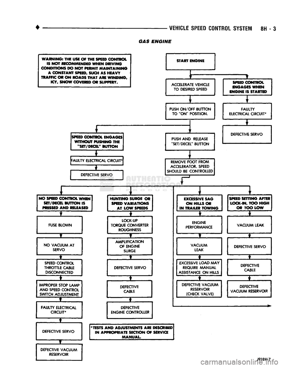
VEHICLE
SPEED
CONTROL
SYSTEM
8H - 3
GAS
ENGINE
warnings the usi of THE
SPEED
control is NOT recommended when
DRIVING
CONDITIONS
DO not
PERMIT
maintaining
A
constant
SPEED, SUCH
AS
HEAVY
TRAFFIC
©r on
ROADS
THAT ARE
WINDING, ICY, SNOW COVERED
OR
SLIPPERY*
START
ENGINE
r
ACCELERATE
VEHICLE TO DESIRED SPEED
SPEED
CONTROL
ENGAGES
WHEN
mmm is
STARTED
PUSH
ON/OFF
BUTTON
TO "ON"
POSITION.
E
FAULTY
ELECTRICAL CIRCUIT*
SPEED
CONTROL ENGAGES
WITHOUT
PUSHING
THE
"SET/DECEL"
BUTTON
PUSH
AND
RELEASE
"SET/DECEL'
'
BUTTON
FAULTY
ELECTRICAL CIRCUIT* DEFECTIVE SERVO
i
DEFECTIVE SERVO
REMOVE
FOOT
FROM
ACCELERATOR.
SPEED
SHOULD
BE
CONTROLLED
T
1
i
1
*
NO
WEED
CONTROL
WHEN
SET/DECEL
BUTTON IS
PRESSED
AND RELEASED
HUNTING
SURGE
OR
SPEED
VARIATIONS AT
LOW
SPEEDS
EXCESSIVE
SAG
ON
HILLS
OR
IN
TRAILER TOWING
SPEED
SETTING AFTER
LOCK-IN,
TOO
HIGH
C3«t LOW
4 *
FUSE
BLOWN
LOCK-UP
TORQUE CONVERTER
ROUGHNESS
ENGINE
PERFORMANCE
VACUUM LEAK
# f
t f
NO
VACUUM
AT
SERVO
AMPLIFICATION
OF ENGINE
SURGE
VACUUM
LEAK
DEFECTIVE SERVO
1
f
it
t
t
SPEED
CONTROL
THROTTLE
CABLE
DISCONNECTED
DEFECTIVE SERVO
EXCESSIVE
LOAD
MAY
REQUIRE MANUAL
ASSISTANCE
ON
HILLS DEFECTIVE
CABLE
i
f
f • *
IMPROPER
STOP LAMP
AND
SPEED CONTROL SWITCH ADJUSTMENT DEFECTIVE
CABLE
DEFECTIVE VACUUM
RESERVOIR
(CHECK VALVE) DEFECTIVE
VACUUM RESERVOIR
1
f
*
FAULTY
ELECTRICAL CIRCUIT* DEFECTIVE
ENGINE
CONTROLLER
DEFECTIVE SERVO
* TESTS AND
ADJUSTMENTS
ARE DESCRIBED
IN
APPROPRIATE
SECTION
OF SERVICE
MANUAL.
DEFECTIVE VACUUM
RESERVOIR
J918H-7
Page 420 of 1502
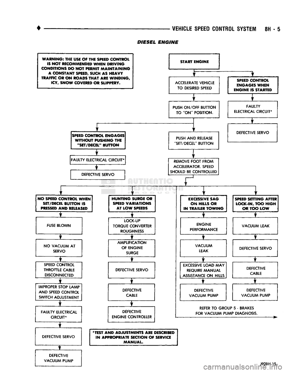
•
^ ^ VEHICLE
SPEED
CONTROL
SYSTEM
8H - I
WARNING:
THE USE OF THE
SPEED
CONTROL
IS
NOT
RECOMMENDED
WHEN DRIVING
CONDITIONS
DO NOT PERMIT MAINTAINING
A
CONSTANT
SPEED,
SUCH AS HEAVY
TRAFFIC
OR ON
ROADS
THAT
ARE WINDING,
ICY,
SNOW
COVERED
OR
SLIPPERY*
SPEED
CONTROL
ENGAGES
WITHOUT PUSHING THE
"SET/DECEL"
BUTTON
±
FAULTY
ELECTRICAL CIRCUIT*
±
DEFECTIVE
SERVO
START ENGINE
ACCELERATE
VEHICLE TO DESIRED SPEED
PUSH
ON/OFF
BUTTON
TO "ON" POSITION.
PUSH
AND
RELEASE
"SET/DECEL"
BUTTON
REMOVE
FOOT
FROM
ACCELERATOR.
SPEED
SHOULD BE CONTROLLED
SPEED
CONTROL
ENGAGES
WHEN
ENGINE IS STARTED
FAULTY
ELECTRICAL
CIRCUIT*
T
DEFECTIVE SERVO
NO
SPEED
CONTROL WHEN
SET/DECEL
BUTTON
IS
PRESSED
AND
RELEASED
FUSE
BLOWN
NO VACUUM AT
SERVO
T
SPEED
CONTROL
THROTTLE
CABLE DISCONNECTED
IMPROPER
STOP LAMP AND SPEED CONTROL SWITCH ADJUSTMENT
FAULTY
ELECTRICAL CIRCUIT*
T
DEFECTIVE SERVO
DEFECTIVE
VACUUM PUMP
HUNTING
SURGE
OR
SPEED
VARIATIONS AT LOW
SPEEDS
I
LOCK-UP
TORQUE CONVERTER
ROUGHNESS
AMPLIFICATION OF ENGINE
SURGE
DEFECTIVE SERVO
DEFECTIVE
CABLE
DEFECTIVE
ENGINE CONTROLLER
EXCESSIVE
SAG
ON HILLS OR
IN TRAILER
TOWING
ENGINE
PERFORAAANCE
VACUUM
LEAK
EXCESSIVE
LOAD MAY
REQUIRE
MANUAL
ASSISTANCE
ON HILLS
DEFECTIVE
VACUUM PUMP
SPEED
SETTING AFTER
LOCK-IN,
TOO
HIGH
OR TOO LOW
T
VACUUM LEAK
DEFECTIVE SERVO DEFECTIVE
CABLE
T
DEFECTIVE
VACUUM PUMP
REFER
TO GROUP 5 - BRAKES
FOR VACUUM PUMP DIAGNOSIS.
"TEST AND ADJUSTMENTS ARE DESCRIBED IN APPROPRIATE SECTION OF SERVICE MANUAL.
J928H-15
DIESEL
ENGINE
Page 612 of 1502
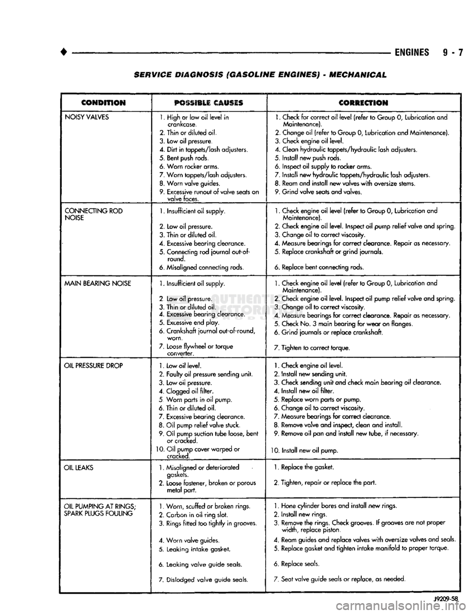
•
ENGINES
9 - 7 SERVICE DIAGNOSIS (GASOLINE ENGINES) - MECHANICAL
CONDITION
PSSSI1LI
CAUSIS
CORRECTION
NOISY
VALVES
1. High
or
low oil
level
in
crankcase.
2. Thin or
diluted
oil.
3.
Low
oil
pressure.
4.
Dirt
in
tappets/lash
adjusters.
5. Bent
push
rods.
6. Worn rocker arms.
7.
Worn
tappets/lash
adjusters.
8.
Worn
valve
guides.
9.
Excessive
runout
of
valve
seats
on
valve
faces.
1.
Check
for
correct oil
level
(refer
to
Group
0,
Lubrication and
Maintenance).
2. Change oil
(refer
to Group
0,
Lubrication and Maintenance).
3. Check engine oil level.
4. Clean hydraulic tappets/hydraulic lash adjusters.
5. Install new
push
rods.
6. Inspect oil supply to rocker arms.
7. Install new hydraulic tappets/hydraulic lash adjusters. 8. Ream and install new valves
with
oversize stems.
9. Grind valve seats and valves.
CONNECTING
ROD
NOISE
1.
Insufficient oil supply.
2.
Low oil
pressure.
3.
Thin
or
diluted
oil.
4.
Excessive
bearing
clearance.
5. Connecting rod
journal
out-of- round.
6. Misaligned connecting rods.
1.
Check engine oil
level
(refer
to Group
0,
Lubrication and
Maintenance).
2. Check engine oil level. Inspect oil pump
relief
valve and spring.
3. Change oil to correct
viscosity.
4. Measure bearings for correct clearance. Repair as necessary, 5. Replace crankshaft or grind journals.
6.
Replace
bent
connecting rods.
MAIN
BEARING
NOISE
1.
Insufficient oil supply.
2 Low
oil
pressure.
3. Thin or
diluted
oil.
4.
Excessive
bearing clearance. 5.
Excessive
end play.
6. Crankshaft
journal
out-of-round, worn,
7.
Loose
flywheel
or
torque
converter.
1.
Check engine oil
level
(refer
to Group
0,
Lubrication and
Maintenance).
2. Check engine oil level. Inspect oil pump
relief
valve and spring.
3. Change oil to correct
viscosity.
4. Measure bearings for correct clearance. Repair as necessary. 5. Check No.
3
main bearing for
wear
on flanges.
6. Grind journals
or
replace crankshaft.
7. Tighten to correct torque.
OIL
PRESSURE
DROP
1.
Low oil level.
2. Faulty oil pressure sending
unit.
3. Low
oil
pressure.
4.
Clogged
oil
filter.
5 Worn parts in
oil
pump.
6. Thin or
diluted
oil.
7.
Excessive
bearing clearance. 8.
Oil
pump
relief
valve stuck.
9. Oil pump suction
tube
loose,
bent
or cracked.
10.
Oil pump cover warped
or
cracked.
1.
Check engine oil level.
2. Install new sending
unit.
3. Check sending
unit
and check main bearing oil clearance.
4. Install new oil
filter.
5. Replace worn parts or pump. 6. Change oil to correct
viscosity.
7. Measure bearings for correct clearance.
8. Remove valve and inspect, clean and install. 9. Remove oil pan and install new tube,
if
necessary.
10. Install new oil pump.
OIL
LEAKS
1.
Misaligned or
deteriorated
gaskets.
2.
Loose
fastener, broken
or
porous
metal
part.
1. Replace the gasket.
2. Tighten,
repair
or replace the
part.
OIL
PUMPING
AT
RINGS;
SPARK
PLUGS
FOULING
1.
Worn, scuffed
or broken
rings.
2. Carbon in oil ring
slot.
3.
Rings
fitted
too
tightly
in grooves.
4. Worn valve guides.
5. Leaking
intake
gasket.
6. Leaking valve guide
seals.
7. Dislodged valve guide
seals.
1.
Hone cylinder bores and install new rings.
2. Install new rings.
3. Remove the rings. Check
grooves.
If
grooves
are not proper width, replace piston.
4. Ream guides and replace valves
with
oversize valves and
seals.
5. Replace gasket and tighten
intake
manifold
to
proper torque.
6. Replace
seals.
7. Seat
valve guide
seals
or
replace, as needed.
J9209-58
Page 625 of 1502
TRANSFER
CASE
INSULATOR
MOUNTING PLATE
NUT(B
RAIL
ASSEMBLY
SPACER
UPPER
INSULATOR
NUT®
LOWER
INSULATOR
J9109-242
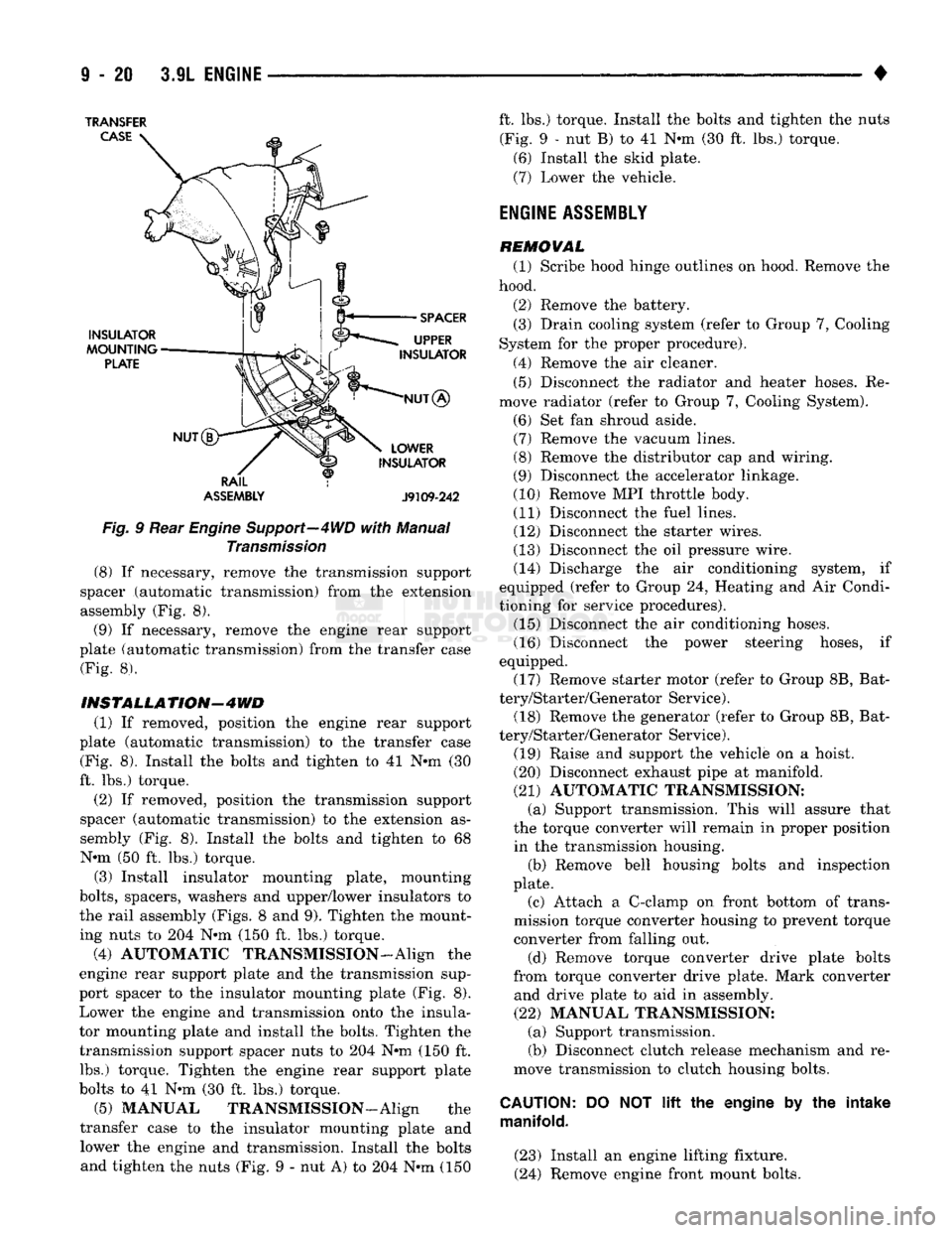
Fig.
9 Rear
Engine
Support—4WD
with
Manual
Transmission
(8) If necessary, remove the transmission support
spacer (automatic transmission) from the extension
assembly (Fig. 8).
(9) If necessary, remove the engine rear support
plate (automatic transmission) from the transfer case (Fig. 8).
INSTALLATION-4WD
(1) If removed, position the engine rear support
plate (automatic transmission) to the transfer case (Fig. 8). Install the bolts and tighten to 41 N-m (30
ft. lbs.) torque.
(2) If removed, position the transmission support
spacer (automatic transmission) to the extension as
sembly (Fig. 8). Install the bolts and tighten to 68 N-m (50 ft. lbs.) torque.
(3) Install insulator mounting plate, mounting
bolts,
spacers, washers and upper/lower insulators to
the rail assembly (Figs. 8 and 9). Tighten the mount
ing nuts to 204 N*m (150 ft. lbs.) torque.
(4) AUTOMATIC TRANSMISSION-Align the
engine rear support plate and the transmission sup
port spacer to the insulator mounting plate (Fig. 8). Lower the engine and transmission onto the insula
tor mounting plate and install the bolts. Tighten the transmission support spacer nuts to 204 N-m (150 ft. lbs.) torque. Tighten the engine rear support plate
bolts to 41 N-m (30 ft. lbs.) torque.
(5) MANUAL TRANSMISSION—Align the
transfer case to the insulator mounting plate and lower the engine and transmission. Install the bolts and tighten the nuts (Fig. 9 - nut A) to 204 N-m (150 ft. lbs.) torque. Install the bolts and tighten the nuts
(Fig. 9 - nut B) to 41 N-m (30 ft. lbs.) torque. (6) Install the skid plate.
(7) Lower the vehicle.
ENGINE
ASSEMBLY
REMOVAL (1) Scribe hood hinge outlines on hood. Remove the
hood.
(2) Remove the battery. (3) Drain cooling system (refer to Group 7, Cooling
System for the proper procedure).
(4) Remove the air cleaner. (5) Disconnect the radiator and heater hoses. Re
move radiator (refer to Group 7, Cooling System).
(6) Set fan shroud aside. (7) Remove the vacuum lines. (8) Remove the distributor cap and wiring.
(9) Disconnect the accelerator linkage.
(10) Remove MPI throttle body. (11) Disconnect the fuel lines. (12) Disconnect the starter wires.
(13) Disconnect the oil pressure wire. (14) Discharge the air conditioning system, if
equipped (refer to Group 24, Heating and Air Condi
tioning for service procedures). (15) Disconnect the air conditioning hoses.
(16) Disconnect the power steering hoses, if
equipped. (17) Remove starter motor (refer to Group 8B, Bat
tery/Starter/Generator Service). (18) Remove the generator (refer to Group 8B, Bat
tery/Starter/Generator Service).
(19) Raise and support the vehicle on a hoist.
(20) Disconnect exhaust pipe at manifold.
(21) AUTOMATIC TRANSMISSION: (a) Support transmission. This will assure that
the torque converter will remain in proper position in the transmission housing. (b) Remove bell housing bolts and inspection
plate.
(c) Attach a C-clamp on front bottom of trans
mission torque converter housing to prevent torque
converter from falling out.
(d) Remove torque converter drive plate bolts
from torque converter drive plate. Mark converter and drive plate to aid in assembly.
(22) MANUAL TRANSMISSION: (a) Support transmission.
(b) Disconnect clutch release mechanism and re
move transmission to clutch housing bolts.
CAUTION:
DO NOT
lift
the engine by the intake
manifold.
(23) Install an engine lifting fixture.
(24) Remove engine front mount bolts.