1993 DODGE TRUCK cooling
[x] Cancel search: coolingPage 4 of 1502
GROUP TAB LOCATOR
Introduction
0
Lubrication
and
Maintenance
2
Front Suspension
and
Axle
3
Rear Suspension
and
Axles
5
Brakes
6
Clutch
7
Cooling System
8
Electrical
9
Engines
11
Exhaust System
and
Intake
Manifold
13
Frame
and Bumpers
14
Fuel
System
16
Propeller Shafts
19
Steering
21
Transmission
and
Transfer Case
22
Wheels and Tires
23
Body Components
24
Heating
and Air
Conditioning
25
Emission Control Systems Component and System Index
Service Manual Comment Forms (Rear
of
Manual)
Page 28 of 1502
•
LUBRICATION AND MAINTENANCE
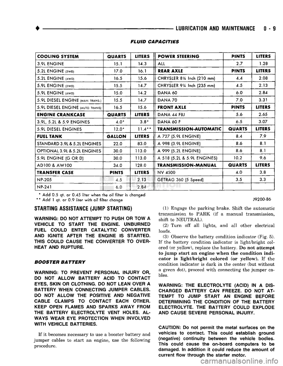
0 - 9 FLUID CAPACITIES
COOLING SYSTEM
QUARTS
LITERS
POWER STEERING PINTS
LITERS
3.9L ENGINE 15.1 14.3
ALL
2.7
1.28
5.2L ENGINE
(2WD)
17.0 16.1
REAR
AXLE
PINTS
LITERS
5.2L ENGINE
(4WD)
16.5 15.6
CHRYSLER
BVa
Inch
(210
mm) 4.4
2.08
5.9L ENGINE
(2WD)
15.5 14.7
CHRYSLER
9Va
Inch
(235
mm) 4.5
2.13
5.9L ENGINE
(4WD)
15.0 14.2
DANA
60 6.0
2.84
5.9L DIESEL ENGINE (MAN.TRANS.) 15.5 14.7
DANA
70 7.0
3.31
5.9L DIESEL ENGINE
(AUTO,
TRANS)
16.5 15.6
FRONT AXLE
PINTS
LITERS
ENGINE
CRANKCASE
QUARTS
LITERS
DANA
44
FBJ 5.6
2.65
3.9L,
5.2L & 5.9
ENGINES 4.0* 3.8*
DANA
60 F
6.5
3.07
5.9L DIESEL ENGINES 12.0*
11.4**
TRANSMISSION-AUTOMATIC
QUARTS
LITERS
FUEL TANK GALLON
LITERS
A
727 (5.9L
ENGINE) 8.4
7.9
STANDARD
3.9L & 5.2L ENGINES 22.0 83.0
A
998 (3.9L
ENGINE) 8.6
8.1
OPTIONAL 3.9L & 5.2L ENGINES 30.0 113.0
A
999 (5.2L
ENGINE) 8.6
8.1
5.9L ENGINE
{G
OR
D)
30.0 113.0
A
518 (5.2L & 5.9L
ENGINES) 10.2
9.6
AD 100
&
AW 100 34.0 128.0
TRANSMISSION-MANUAL
QUARTS
LITERS
TRANSFER
CASE
PINTS
LITERS
NV
4500
4.0
3.8
NP-205
4.5 2.13
GETRAG
360 (5
Speed)
3.5
3.3
NP-241
6.0
2.84
* Add
0.5 qt. or 0.45
liter
when
the oil filter
is
changed
*
*
Add
1 qt. or 0.9
liter
with
oil filter
change STARTING ASSISTANCE (JUMP STARTING)
WARNING:
DO NOT
ATTEMPT
TO
PUSH
OR
TOW
A
VEHICLE
TO
START
THE
ENGINE. UNBURNED FUEL COULD ENTER CATALYTIC CONVERTER
AND IGNITE AFTER
THE
ENGINE
IS
STARTED.
THIS COULD CAUSE
THE
CONVERTER
TO
OVER HEAT AND RUPTURE.
BOOSTER BATTERY
WARNING:
TO
PREVENT PERSONAL INJURY
OR,
DO
NOT
ALLOW BATTERY ACID
TO
CONTACT
EYES,
SKIN
OR
CLOTHING.
DO NOT
LEAN OVER
A
BATTERY WHEN CONNECTING JUMPER
CABLES.
DO
NOT
ALLOW
THE
POSITIVE
AND
NEGATIVE
CABLE
CLAMPS
TO
CONTACT EACH OTHER.
KEEP
OPEN FLAMES
AND
SPARKS
AWAY FROM
THE BATTERY ELECTROLYTE VENT HOLES.
AL
WAYS
WEAR
EYE
PROTECTION WHEN INVOLVED
WITH
VEHICLE BATTERIES.
If it becomes necessary to use a booster battery and
jumper cables to start an engine, use the following procedure.
J9200-86
(1) Engage the parking brake. Shift the automatic
transmission to PARK (if a manual transmission, shift to NEUTRAL).
(2) Turn off all lights, and all other electrical
loads.
(3)
Observe the battery condition indicator (Fig. 5).
If the battery condition indicator is light/bright col
ored (or yellow), replace the battery. Do not attempt
to jump start an engine when the condition indi
cator is light/bright colored (or yellow). If the
condition indicator is dark in the center (but without a green dot), proceed with connecting the jumper ca
bles.
WARNING:
THE
ELECTROLYTE (ACID)
IN A
DIS
CHARGED
BATTERY
CAN
FREEZE.
DO NOT AT
TEMPT
TO
JUMP START
AN
ENGINE BEFORE DETERMINING
THE
CONDITION
OF THE
BATTERY
ELECTROLYTE.
THE
BATTERY COULD EXPLODE
AND CAUSE SEVERE PERSONAL INJURY.
CAUTION:
Do not
permit
the
metal
surfaces
on the
vehicles
to
contact.
This
could
establish
ground
(negative)
continuity
between
the
vehicle
bodies.
This
could
cause
the
on-board
computers
to be
damaged.
In
addition
it
could
reduce
the
amount
of
current
flow
through
the
starter
motor.
Page 33 of 1502

0 - 14
LUBRICATION
AND
MAINTENANCE
•
ENGINE
MAINTENANCE
INDEX
page
Air
Injection
Systems/Air Pump
. 17
Air-Conditioner
Compressor
21
Battery
19
Cooling System
15
Crankcase
Ventilation
System
17
Diesel Engine
Air Filter
Canister
17
Drive Belts
20
Engine
Air
Cleaner
Filter
Element
16
Engine Break-In
14
Engine
Oil 14
Engine
Oil
Change
and Filter
Replacement
15
Exhaust Gas
Recirculation
(EGR) System
...... 19
page
Exhaust
Manifold
Heat
Control
Valve
. 17
Exhaust System
, 21
Fuel System
18
Hoses
and
Fittings
16
Ignition
Cables,
Distributor
Cap and
Rotor
...... 19
Ignition
Timing
. 19
Oxygen
(02)
Sensor
19
Rubber/Plastic Components
20
Spark Plugs
. 19
Throttle
Control
Linkage
18
Vacuum Operated, Emission
Control
Components
19
ENGINE BREAK-IN
After first starting a new engine, allow it to idle
for 15 seconds before shifting into a drive gear. Also:
• Drive the vehicle at varying speeds less than 88
km/h (55 mph) for the first 480 km (300 miles).
• Avoid fast acceleration and sudden stops.
• Do not drive at full-throttle for extended periods of
time
• Do not drive at constant speeds
• Do not idle the engine excessively A special break-in engine oil is not required. The
original engine oil installed is a high quality lubri
cant. New engines tend to consume more fuel and oil un
til after the break-in period has ended.
ENGINE
OIL SPECIFICATIONS
API SERWICE
GRADE
Use an engine oil that conforms to API Service
Grade S5 SG/CD or SG/CE. MOPAR®provides engine
oils that conform to all of these service grades.
SULFATED ASH—DIESEL ENGINES
Oils that contain an excessive amount of sulfated
ash can cause deposits to develop on Diesel engine
valves. These deposits can result in valve wear.
SAE
WISC0SITY
An SAE viscosity grade is used to specify the vis
cosity of engine oil. SAE 30 specifies a single viscos
ity engine oil.
Engine oils also have multiple viscosities. 10W-30
<
5W-30
1
1 1
F
-20 0 10 20 32 60 80 100
C
-29 -18 -12 -7 0 16 27 38
ANTICIPATED
TEMPERATURE RANGE BEFORE
NEXT
OIL
CHANGE
J9000-39
Fig.
1 Temperature/Engine Oil Viscosity—Gasoline
Engines
-12°C
-18°C 10°F
0°F- 15W-40
-23°c(^-10eF
I
10W-30
WITH
WITHOUT
BLOCK HEATER
BLOCK
SYNTHETIC
OIL
HEATER
10W-30 5W-30
J9100-29
Fig.
2 Temperature/Engine Oil Viscosity—Diesel
Engines
ENERGY
G0NSERWING
OIL
An Energy Conserving type oil is recommended for
gasoline engines. They are designated as either EN
ERGY CONSERVING or ENERGY CONSERVING
II.
OIL
LEVEL
INDICATOR (DIPSTICK)
GASOLINE ENGINES
The engine oil indicator is located at the right
front of the engine.
Page 34 of 1502

•
LUBRICATION
AND
MAINTENANCE
0 - 15
DIESEL
ENGINES
The Diesel engine oil level indicator is located at
the left center of the engine, above the
fuel
injection
pump (Fig. 3).
Fig.
3
Diesel
Engine
Oil
Dipstick
ACCEPTABLE
OIL
LEVEL
To maintain proper lubrication of an engine, the
engine oil must be maintained at an acceptable level.
For gasoline engines, the acceptable levels are indi cated between the ADD and
FULL
marks on oil
dip
stick. For Diesel engines, the acceptable levels are
indicated between the L (low) and H
(high) marks
on
oil dipstick. The oil level should be checked periodically. The
vehicle should be on a level surface. Wait for
five
minutes after stopping the engine. For gasoline en
gines,
add oil only when the level indicated on the
dipstick is at or below the ADD mark. For Diesel en
gines,
add oil only when the level indicated on the
dipstick is between the L and H marks.
Never oper
ate a Diesel
engine when
the oil
level
is below
the L mark. The distance between the L and H
marks represents 1.9L (2 Qts) engine oil.
CAUTION:
Do not
overfill
an
engine crankcase
with
oil. This
will
cause
oil
aeration
and
result
in a de
crease
in the
engine
oil
pressure.
ENGINE
OIL
CHANGE AND FILTER REPLACEMENT
WARNING: PROTECTIVE CLOTHING
AND
GLOVES SHOULD
BE
WORN. EXPOSED SKIN SHOULD
BE
WASHED
WITH
SOAP
AND
WATER
TO
REMOVE
USED
ENGINE
OIL.
DO NOT
USE
GASOLINE, THIN
NER,
OR
SOLVENTS
TO
REMOVE ENGINE
OIL
FROM
SKIN.
DO NOT
POLLUTE. DISPOSE
OF
USED
ENGINE
OIL
PROPERLY.
ENGINE
OIL
FILTER
All engines are equipped with a throw-away type
oil filter. The same type of filter is recommended
when the filter is changed.
OIL CHANGE
AND
FILTER
REPLACEMENT
Bring engine up to normal operating temperature.
A more complete drainage of oil will result.
(1) Remove the drain hole plug and drain the en
gine oil from the crankcase.
(2) Install the drain hole plug with a replacement
gasket. For gasoline engines, the oil filter should be
replaced during every second engine oil change.
For Diesel engines, the oil filter should be re
placed during every engine oil change.
(3) Rotate the oil filter counterclockwise to remove
it.
(4) Clean the engine cylinder block oil filter boss. (5) Apply a light coat of new engine oil to the rub
ber seal on the oil filter.
(6) Install and hand tighten the oil filter 1/2 to 3/4
of a turn clockwise. (7) Add new engine oil at the fill hole location on
top of the engine cylinder head cover. Wipe off any spilled oil.
(8) Observe the oil level on the dipstick.
CAUTION:
Do not
overfill
the
engine crankcase
with
oil.
(9)
Start the engine. Observe the oil pressure
gauge or warning lamp (as applicable). If the oil
pressure does not increase, stop the engine immedi ately. Check oil level.
COOLING SYSTEM
WARNING:
USE
EXTREME CAUTION WHEN
THE
ENGINE
IS
OPERATING.
DO NOT PUT
YOUR
HANDS NEAR
THE
DRIVE BELT(S), PULLEYS
OR
FAN BLADE.
DO NOT
STAND
IN A
DIRECT LINE
WITH
THE FAN
BLADE.
INSPECTION SCHEDULE
Determine the coolant level. Inspect the cooling
system hoses/clamps after each service interval has
elapsed.
COOLANT LEVEL
It is recommended that the engine coolant level be
inspected at least once a month during periods of hot
weather.
With the engine at normal operating temperature,
check the coolant level in the coolant reserve tank.
The coolant level must be at least above the ADD mark. Add coolant to the coolant reserve tank only.
Page 35 of 1502
0-18
LUBRICATION
AND
MAINTENANCE
•
COOLANT FREEZE PROTECTION
Cooling systems contain a 50/50 mixture of anti
freeze (ethylene glycol) and distilled water. This is
the recommended coolant mixture.
It is recommended that the degree of coolant pro
tection be tested every 12 months. If the coolant is
contaminated or rusty, the cooling system should be
drained, flushed. Refill with a 50/50 mixture of fresh
coolant. Refer to Group 7—Cooling Systems for addi
tional information.
SYSTEM
INSPECTION
WARNING:
IF THE
ENGINE
HAS
BEEN RECENTLY
OPERATED,
DO NOT
REMOVE
THE
RADIATOR
CAP.
THIS WILL AVOID
YOU
BEING SCALDED
WITH
HOT, PRESSURIZED COOLANT.
(1) Test the radiator cap for proper sealing and op
eration. Use caution when removing the radiator cap
to avoid contact with hot coolant. Place a heavy rag
or towel over the cap and turn to the first stop. Do
not press down. Pause to allow the pressure to re
lease through the overflow tube. Then press down
and turn counterclockwise to remove the cap.
(2) Inspect the coolant overflow tubing and the
connections at the coolant reserve tank and at the
radiator.
(3) Inspect the entire cooling system for leaks. A
black-light detector can be used as an aid in detect ing the source of coolant leaks.
(4) Inspect the radiator and air conditioner con
denser fins for debris, etc. (5) If necessary, refer to Group 7—Cooling Systems
for additional information and service procedures.
RADIATOR CAP
The radiator cap must be completely tightened to
provide proper pressure. Inspect and test radiator cap
when cooling system service is performed.
MAIN,
FLUSH
AND
FILL
WARNING: ANTI-FREEZE (ETHYLENE GLYCOL)
IS
POISONOUS.
KEEP
OUT OF THE
REACH
OF
CHIL
DREN.
Drain, flush, and fill the cooling system at the in
terval specified in maintenance schedule. For proper service instructions see Group 7, Cooling System.
HOSES AND
FITTINGS
It is recommended that rubber hoses be periodi
cally inspected. Inspect all hose fittings for looseness and corrosion.
ENGINE
AIR
CLEANER
FILTER
ELEMENT
MAINTENANCE
SCHEDULE
With normal driving conditions, the engine air
cleaner filter element should be replaced:
• Light-Duty Cycle-after each 48 000 km (30,000
miles) interval has elapsed
• Heavy-Duty Cycle-after
each
38 000 km (24,000
miles) interval has elapsed
When the vehicle is operated in dusty areas, the
filter element should be replaced more often.
For Diesel engines, the air filter canister should be
cleaned at the same time the filter is replaced.
SERVICE/REPLACEMENT
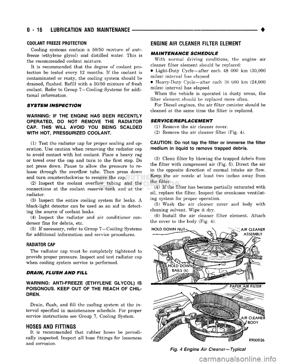
(1) Remove the air cleaner cover.
(2) Remove the air cleaner filter (Fig. 4).
CAUTION:
Do not tap the filter or immerse the filter medium in liquid to remove trapped debris.
(3) Clean filter by blowing the trapped debris from
the filter with compressed air (Fig. 5). Direct the air in the opposite direction of normal intake air flow.
Keep the air nozzle at least two inches away from
the filter.
(4) If the filter has become partially saturated with
oil,
replace the filter. Inspect the crankcase ventilat
ing system for proper operation.
(5) Wash the air cleaner cover and body with
cleaning solvent. Wipe it dry.
(6) Install the air cleaner filter element. Attach
the cover to the body (Fig. 4).
Fig,
4
Engine
Air Oeaner—
Typical
Page 39 of 1502
0
- 21
LUBRICATION
AND
MAINTENANCE
• SERVICE INFORMATION
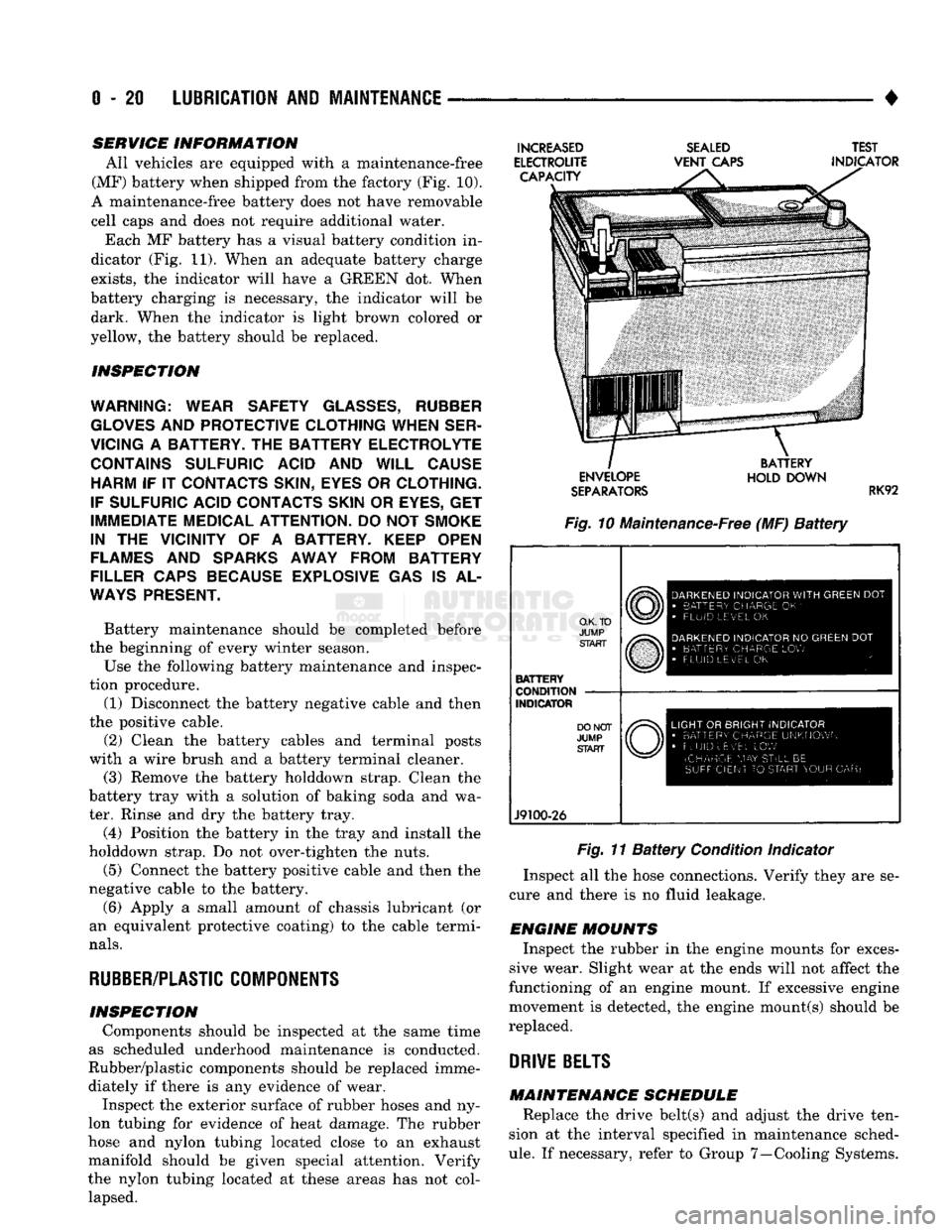
All vehicles are equipped with a maintenance-free
(MF) battery when shipped from the factory (Fig. 10).
A maintenance-free battery does not have removable
cell caps and does not require additional water. Each MF battery has a visual battery condition in
dicator (Fig. 11). When an adequate battery charge
exists,
the indicator will have a GREEN dot. When
battery charging is necessary, the indicator will be dark. When the indicator is light brown colored or
yellow, the battery should be replaced.
INSPECTION
WARNING; WEAR SAFETY
GLASSES,
RUBBER
GLOVES
AND
PROTECTIVE CLOTHING WHEN SER
VICING
A
BATTERY.
THE
BATTERY ELECTROLYTE CONTAINS SULFURIC ACID
AND
WILL CAUSE HARM
IF IT
CONTACTS SKIN, EYES
OR
CLOTHING.
IF SULFURIC ACID CONTACTS SKIN
OR
EYES,
GET
IMMEDIATE MEDICAL ATTENTION.
DO
NOT
SMOKE
IN
THE
VICINITY
OF A
BATTERY. KEEP OPEN
FLAMES
AND
SPARKS AWAY FROM BATTERY
FILLER CAPS BECAUSE EXPLOSIVE
GAS IS AL
WAYS
PRESENT.
Battery maintenance should be completed before
the beginning of every winter season.
Use the following battery maintenance and inspec
tion procedure. (1) Disconnect the battery negative cable and then
the positive cable.
(2) Clean the battery cables and terminal posts
with a wire brush and a battery terminal cleaner. (3) Remove the battery holddown strap. Clean the
battery tray with a solution of baking soda and wa
ter. Rinse and dry the battery tray.
(4) Position the battery in the tray and install the
holddown strap. Do not over-tighten the nuts.
(5) Connect the battery positive cable and then the
negative cable to the battery.
(6) Apply a small amount of chassis lubricant (or
an equivalent protective coating) to the cable termi
nals.
RUBBER/PLASTIC
COMPONENTS
INSPECTION Components should be inspected at the same time
as scheduled underhood maintenance is conducted.
Rubber/plastic components should be replaced imme diately if there is any evidence of wear. Inspect the exterior surface of rubber hoses and ny
lon tubing for evidence of heat damage. The rubber
hose and nylon tubing located close to an exhaust
manifold should be given special attention. Verify
the nylon tubing located at these areas has not col lapsed.
INCREASED
ELECTROUTE CAPACITY
SEALED
VENT
CAPS TEST
INDICATOR ENVELOPE
SEPARATORS
BATTERY
HOLD DOWN
RK92
Fig. 10 Maintenance-Free (MF)
Battery
O.K. TO
JUMP START
BATTERY
CONDITION
INDICATOR
J9100-26
DARKENED
INDICATOR
WITH
GREEN
DOT
•
BATTERY CHARGE
OK '
•
FLUID LEVEL
OK
DARKENED
INDICATOR
NO
GREEN
DOT
•
BATTERY CHARGE
LOW
FLUID LEVEL
OK
LIGHT
OR
BRIGHT INDICATOR
•
BATTERY CHARGE UNKNOWN
•
FLUID uEv'EL
LOW
(CHARGE
MAY
STILL
BE
SUFFICIENT
TO
START YOUR
CAR)
Fig. 11
Battery
Condition Indicator
Inspect all the hose connections. Verify they are se
cure and there is no fluid leakage.
ENGINE MOUNTS Inspect the rubber in the engine mounts for exces
sive wear. Slight wear at the ends will not affect the
functioning of an engine mount. If excessive engine
movement is detected, the engine mount(s) should be
replaced.
DRIVE
BELTS
MAINTENANCE SCHEDULE Replace the drive belt(s) and adjust the drive ten
sion at the interval specified in maintenance sched
ule.
If necessary, refer to Group 7—Cooling Systems.
Page 270 of 1502

•
CLUTCH
6-17
CLUTCH PEDAL INSTALLATION
(1) Lubricate pedal shaft, pedal shaft bore and all
bushings with Mopar Multi Mileage grease. (2) Insert pedal pin into cylinder push rod. Then
position clutch pedal in support. (3) Slide pedal shaft through clutch pedal bore and
bushings. (4) Install bolt that retains pedal shaft in support.
(5) Secure push rod to pedal pin with wave washer,
flat washer and retaining ring.
FLYWHEEL SERVICE
Inspect the flywheel whenever the clutch disc,
cover and housing are removed for service. Check
condition of the flywheel face, hub, ring gear teeth,
and flywheel bolts. Minor scratches, burrs, or glazing on the flywheel
face can be scuff sanded with 180 grit emery cloth. However, the flywheel should be replaced if the disc
contact surface is severely scored, heat checked,
cracked, or obviously worn. Cleanup of minor flywheel scoring should be per
formed with surface grinding equipment. Remove
only enough material to reduce scoring (approximate
ly 0.001 - 0.003 in.). Heavy stock removal is not rec
ommended. Replace the flywheel if scoring is severe
and deeper than 0.076 mm (0.003 in.). Excessive
stock removal can result in flywheel cracking or
warpage after installation; it can also weaken the flywheel and interfere with proper clutch release. Check flywheel runout if misalignment is sus
pected. Runout should not exceed 0.08 mm (0.003
in.).
Measure runout at the outer edge of the fly
wheel face with a dial indicator. Mount the dial in
dicator on a stud installed in place of one of the
flywheel attaching bolts. Clean the crankshaft flange before mounting the
flywheel. Dirt and grease on the flange surface may cock the flywheel causing excessive runout. Check condition of the flywheel hub and attaching
bolts.
Replace the flywheel if the hub exhibits cracks in the area of the attaching bolt holes. Install new attaching bolts whenever the flywheel
is replaced and use Mopar Lock N' Seal, or Loctite
242 on replacement bolt threads.
Recommended flywheel bolt torques are:
• 75 N»m (55 ft. lbs.) for gas engine flywheels
• 137 N*m (101 ft. lbs.) for diesel flywheels Inspect the teeth on the starter ring gear. If the
teeth are worn or damaged, the flywheel should
be replaced as an assembly. This is the recom mended and preferred method of repair.
In cases where a new flywheel is not readily avail
able,
a replacement ring gear can be installed. How
ever, the following precautions must be observed to
avoid damaging the flywheel and replacement gear.
(a) Mark position of the old gear for alignment
reference on the flywheel. Use a scriber for this
purpose.
(b) Wear protective goggles or approved safety
glasses. Also wear heat resistent gloves when han
dling a heated ring gear. (c) Remove the old gear by cutting most of the
way through it (at one point) with an abrasive cut off wheel. Then complete removal with a cold chisel
or punch. (d) The ring gear is a shrink fit on the flywheel.
This means the gear must be expanded by heating in order to install it. The method of heating and expanding the gear is extremely important. Ev
ery surface of the gear must be heated at the same
time to produce uniform expansion. An oven or
similar enclosed heating device must be used. Tem
perature required for uniform expansion is 325-350° F.
CAUTION:
Never
use an
oxy/acetylene torch
to re
move
the old
gear,
or to
heat
and
expand
a new
gear.
The
high temperature
of the
torch flame
will
cause
localized heating
and
damage
the
flywheel.
In
addition,
using
the
torch
to
heat
a
replacement gear
will
cause uneven heating
and
expansion.
The
torch
flame
will
also
anneal
the
gear
teeth
resulting
in
rapid wear
and
damage
after
installation.
(e) The heated gear must be installed evenly to
avoid misalignment or distortion. A shop press and
suitable press plates should be used to install the
gear if at all possible.
(f) Be sure to wear eye and hand protection.
Heat resistent gloves and safety goggles are needed
for personal safety. Also use metal tongs, vise
grips,
or similar tools to position the gear as necessary for installation.
(g) Allow the flywheel and ring gear to cool
down before installation. Set the assembly on a
workbench and let it cool in normal shop air.
CAUTION:
Do not
use water,
or
compressed
air to
cool
the
flywheel.
The
rapid cooling produced
by
water
or
compressed
air can
distort,
or
crack
the
gear
and
flywheel.
Page 272 of 1502
COOLING SYSTEM
CONTENTS page
DIAGNOSIS
... 4
ENGINE
ACCESSORY
DRIVE BELTS
40
ENGINE
BLOCK HEATERS
48
GENERAL
INFORMATION
Throughout this group, references are made to partic
ular vehicle models by alphabetical designation or by
the particular vehicle nameplate. A chart showing a
breakdown of alphabetical designations is included in
the Introduction section at the beginning of this man
ual.
5.9L gas powered engines will be' referred to as ei
ther: LDC (Light Duty Cycle) or HDC (Heavy Duty
Cycle).
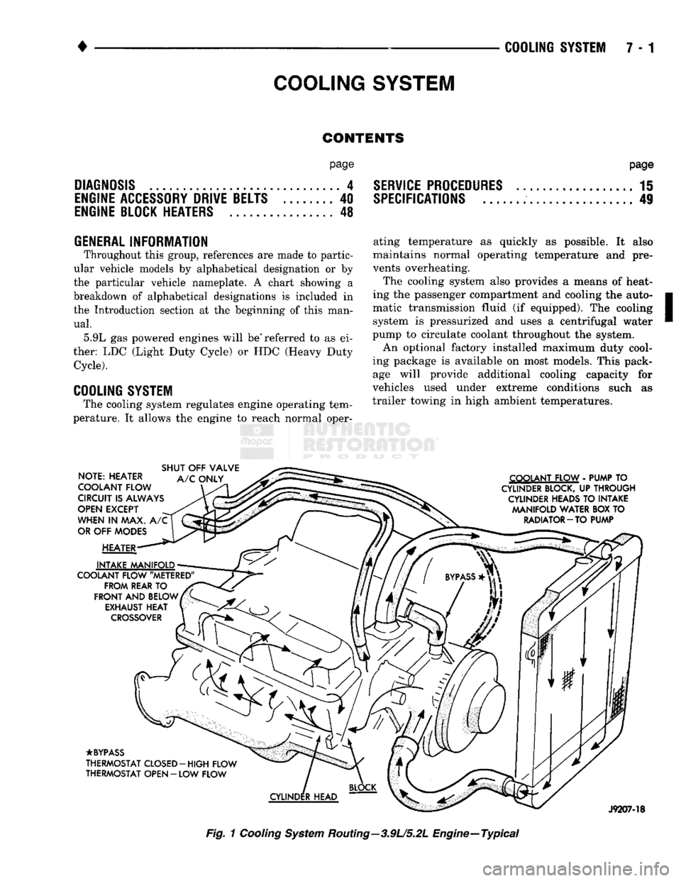
COOLING
SYSTEM
The cooling system regulates engine operating tem
perature. It allows the engine to reach normal oper-
page
SERVICE
PROCEDURES
15
SPECIFICATIONS
; 49
ating temperature as quickly as possible. It also
maintains normal operating temperature and pre
vents overheating.
The cooling system also provides a means of heat
ing the passenger compartment and cooling the auto
matic transmission fluid (if equipped). The cooling system is pressurized and uses a centrifugal water
pump to circulate coolant throughout the system.
An optional factory installed maximum duty cool
ing package is available on most models. This pack age will provide additional cooling capacity for
vehicles used under extreme conditions such as
trailer towing in high ambient temperatures.
NOTE: HEATER
COOLANT FLOW
CIRCUIT
IS
ALWAYS
OPEN
EXCEPT
WHEN
IN MAX. A/C
OR
OFF
MODES
HEATER
INTAKE MANIFOLD
COOLANT FLOW "METERED" FROM REAR
TO
FRONT
AND
BELOW EXHAUST
HEAT
CROSSOVER
SHUT
OFF
VALVE
A/C
ONLY COOLANT FLOW
-
PUMP
TO
CYLINDER BLOCK,
UP
THROUGH CYLINDER HEADS
TO
INTAKE MANIFOLD WATER
BOX TO
RADIATOR-TO PUMP
•BYPASS
THERMOSTAT CLOSED-HIGH FLOW
THERMOSTAT OPEN
- LOW
FLOW
J9207-18
Fig.
1
Cooling
System
Routing—3.9U5.2L Engine—Typical