1993 DODGE TRUCK hood open
[x] Cancel search: hood openPage 516 of 1502
WIRING
DIAGRAMS
SW - 41
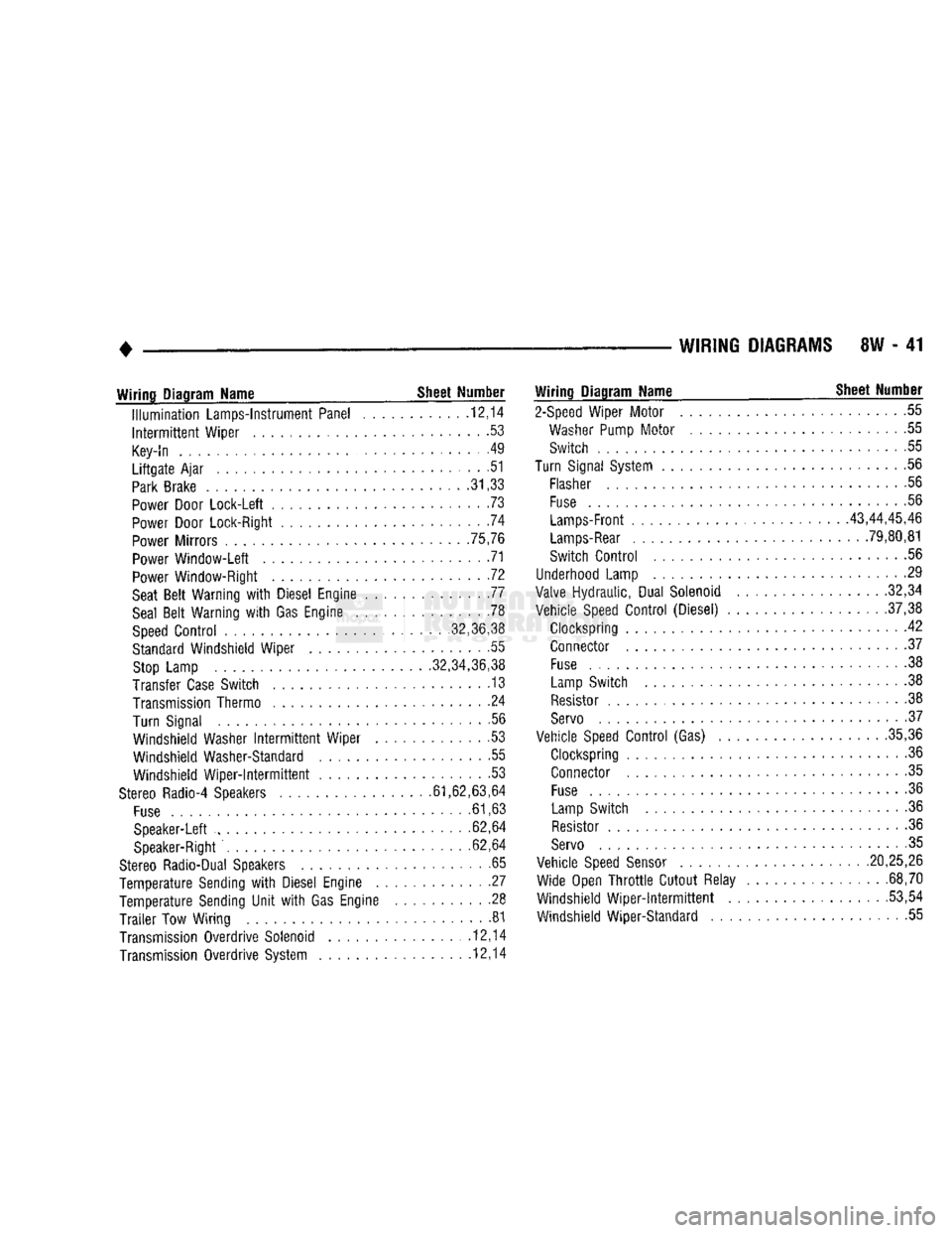
Wiring
Diagram Name _ Sheet Number
Illumination
Lamps-Instrument Panel ........... .12,14
Intermittent
Wiper ......................... .53
Key-In
. . . . . . . .49
Liftgate
Ajar
............................ .51
Park
Brake
.31,33
Power
Door Lock-Left ....................... .73
Power
Door Lock-Right .74
Power
Mirrors .75,76
Power
Window-Left 71
Power
Window-Right . .72
Seat
Belt
Warning
with
Diesel Engine 77
Seal
Belt
Warning
with
Gas Engine .78
Speed
Control
........... ,32,36,38
Standard
Windshield Wiper . .55
Stop
Lamp .32,34,36,38
Transfer
Case
Switch . 13
Transmission
Thermo ....................... .24
Turn Signal .56
Windshield Washer
Intermittent
Wiper . .53
Windshield Washer-Standard .55 Windshield
Wiper-Intermittent
53
Stereo
Radio-4 Speakers .61,62,63,64
Fuse
.61,63
Speaker-Left ......... ............ 62,64
Speaker-Right
. .62,64
Stereo
Radio-Dual Speakers .65
Temperature Sending
with
Diesel Engine . .27
Temperature Sending
Unit
with
Gas Engine .......... .28
Trailer
Tow Wiring 81
Transmission
Overdrive Solenoid ............... .12,14
Transmission
Overdrive System 12,14
Wiring
Diagram Name ^ Sheet Number
2-Speed
Wiper Motor 55
Washer
Pump
Motor
....................... .55
Switch 55
Turn
Signal
System
.......................... .56
Flasher
56
Fuse
.56
Lamps-Front
43,44,45,46
Lamps-Rear
. 79,80,81
Switch
Control
56
Underhood
Lamp 29
Valve
Hydraulic, Dual Solenoid .32,34
Vehicle
Speed
Control
(Diesel) .37,38
Clockspring 42 Connector .37
Fuse
................................. .38
Lamp
Switch . . .38
Resistor
.38
Servo
• .37
Vehicle
Speed
Control
(Gas) .35,36
Clockspring 36
Connector .35
Fuse
......... 36
Lamp
Switch .36
Resistor
.36
Servo
. 35
Vehicle
Speed
Sensor
.20,25,26 Wide Open
Throttle
Cutout Relay . .68,70
Windshield
Wiper-intermittent
...... ....... .53,54
Windshield Wiper-Standard 55
Page 607 of 1502
9
- 2
ENGINES
rial surrounds each mounting hole. Excess material
can easily be wiped off. Components should be
torqued in place within 15 minutes. The use of a lo cating dowel is recommended during assembly to pre
vent smearing the material off location.
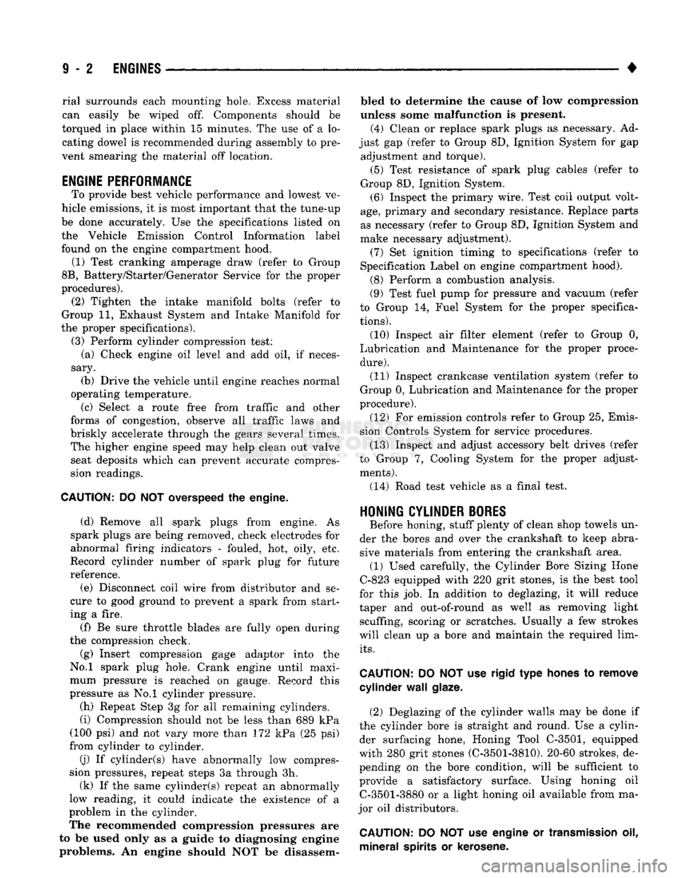
ENGINE PERFORMANCE
To provide best vehicle performance and lowest ve
hicle emissions, it is most important that the tune-up
be done accurately. Use the specifications listed on
the Vehicle Emission Control Information label found on the engine compartment hood.
(1) Test cranking amperage draw (refer to Group
8B,
Battery/Starter/Generator Service for the proper
procedures).
(2) Tighten the intake manifold bolts (refer to
Group 11, Exhaust System and Intake Manifold for
the proper specifications). (3) Perform cylinder compression test:
(a) Check engine oil level and add oil, if neces
sary.
(b) Drive the vehicle until engine reaches normal
operating temperature. (c) Select a route free from traffic and other
forms of congestion, observe all traffic laws and
briskly accelerate through the gears several times. The higher engine speed may help clean out valve seat deposits which can prevent accurate compres
sion readings.
CAUTION:
DO NOT
overspeed
the
engine.
(d) Remove all spark plugs from engine. As
spark plugs are being removed, check electrodes for
abnormal firing indicators - fouled, hot, oily, etc.
Record cylinder number of spark plug for future
reference.
(e) Disconnect coil wire from distributor and se
cure to good ground to prevent a spark from start
ing a fire.
(f) Be sure throttle blades are fully open during
the compression check. (g) Insert compression gage adaptor into the
No.l spark plug hole. Crank engine until maxi
mum pressure is reached on gauge. Record this
pressure as No.l cylinder pressure.
(h) Repeat Step 3g for all remaining cylinders.
(i) Compression should not be less than 689 kPa
(100 psi) and not vary more than 172 kPa (25 psi)
from cylinder to cylinder.
(j) If cylinder(s) have abnormally low compres
sion pressures, repeat steps 3a through 3h. (k) If the same cylinder(s) repeat an abnormally
low reading, it could indicate the existence of a
problem in the cylinder.
The recommended compression pressures are
to be used only as a guide to diagnosing engine
problems. An engine should NOT be disassem bled to determine the cause of low compression
unless some malfunction is present. (4) Clean or replace spark plugs as necessary. Ad
just gap (refer to Group 8D, Ignition System for gap adjustment and torque).
(5) Test resistance of spark plug cables (refer to
Group 8D, Ignition System.
(6) Inspect the primary wire. Test coil output volt
age,
primary and secondary resistance. Replace parts as necessary (refer to Group 8D, Ignition System and
make necessary adjustment).
(7) Set ignition timing to specifications (refer to
Specification Label on engine compartment hood).
(8) Perform a combustion analysis.
(9) Test fuel pump for pressure and vacuum (refer
to Group 14, Fuel System for the proper specifica
tions).
(10) Inspect air filter element (refer to Group 0,
Lubrication and Maintenance for the proper proce
dure).
(11) Inspect crankcase ventilation system (refer to
Group 0, Lubrication and Maintenance for the proper
procedure).
(12) For emission controls refer to Group 25, Emis
sion Controls System for service procedures.
(13) Inspect and adjust accessory belt drives (refer
to Group 7, Cooling System for the proper adjust
ments).
(14) Road test vehicle as a final test.
H0NIN6
CYLINDER
BORES
Before honing, stuff plenty of clean shop towels un
der the bores and over the crankshaft to keep abra sive materials from entering the crankshaft area.
(1) Used carefully, the Cylinder Bore Sizing Hone
C-823 equipped with 220 grit stones, is the best tool
for this job. In addition to deglazing, it will reduce
taper and out-of-round as well as removing light scuffing, scoring or scratches. Usually a few strokes
will clean up a bore and maintain the required lim
its.
CAUTION:
DO NOT use rigid type
hones
to remove
cylinder
wall
glaze.
(2) Deglazing of the cylinder walls may be done if
the cylinder bore is straight and round. Use a cylin
der surfacing hone, Honing Tool C-3501, equipped
with 280 grit stones (C-3501-3810). 20-60 strokes, de
pending on the bore condition, will be sufficient to
provide a satisfactory surface. Using honing oil C-3501-3880 or a light honing oil available from ma
jor oil distributors.
CAUTION:
DO NOT use engine or
transmission
oil, mineral
spirits
or
kerosene.
Page 1384 of 1502
•
BODY
COMPONENTS
23 - 1
CONTENTS
page
page
CAB/BODY
INTERIOR COMPONENTS
35
FIXED
GLASS
. 29
DOORS
21
PAINT
CODE
CHART
54
EXTERIOR
COMPONENTS
1
REFINISHING
PROCEDURES
54
EXTERIOR COMPONENTS
INDEX
page
Battery
Tray
7
Blower Motor Housing
Insulation
Panel—Diesel
Engine
Only
7
Body
Mouldings, Nameplates
and
Decals .......
9
Cab
. 14
Cab/Body
and
Cargo
Box
Stripes
11
Cargo
Box
19
Cowl
Grille
7
Front
Fenders
8
Fuel
Filler
Door
and
Nozzle/Tubes
12
Grille
and
Grille
Extension Panel
1
Grille
Extension Panel Support Bracket
(With
Diesel Engine Only)
3
page
Grille
Opening Panel (GOP)
and
Radiator Support Panel
3
Hatchgate
and
Components
16
Hood
5
Hood
Inside Release Cable
5
Hood
Latch
4
Labels/Decals/Plates
1
Outside Mirrors
13
Roof
Vent—Ramcharger
. 20
Splash
Shields—Front Fender
9
Sport
Bar
18
Tailgate
14
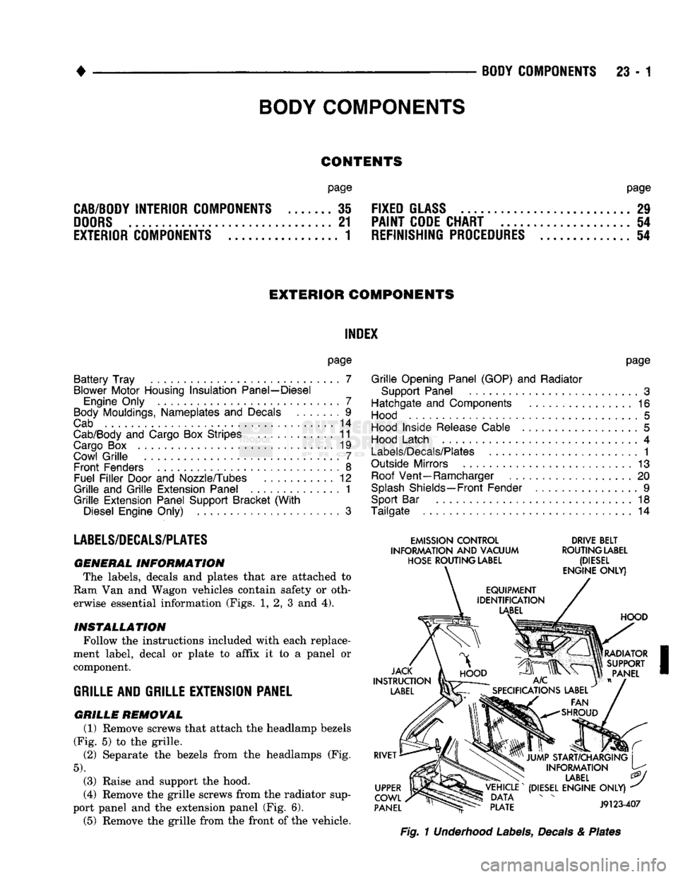
LABELS/DECALS/PLATES
GENERAL
INFORMATION The labels, decals
and
plates that
are
attached
to
Ram Van
and
Wagon vehicles contain safety
or
oth erwise essential information (Figs.
1, 2, 3 and 4).
INSTALLATION
Follow the instructions included with each replace
ment label, decal
or
plate
to
affix
it to a
panel
or
component.
GRILLE
AND GRILLE EXTENSION PANEL
GRILLE
REMOVAL (1) Remove screws that attach the headlamp bezels
(Fig.
5) to the
grille.
(2)
Separate
the
bezels from
the
headlamps
(Fig.
5).
(3) Raise
and
support
the
hood.
(4) Remove the grille screws from the radiator sup
port panel
and the
extension panel (Fig.
6).
(5) Remove
the
grille from the front
of
the vehicle.
EMISSION
CONTROL
DRIVE
BELT
INFORMATION
AND
VACUUM
ROUTING
LABEL
HOSE
ROUTING
LABEL
(DIESEL
Fig.
1 Underhood Labels, Decals & Plates
BODY
COMPONENTS
Page 1386 of 1502
•
BODY
COMPONENTS
23 - 3
GRILLE
EXTENSION
PANEL
INSTALLATION
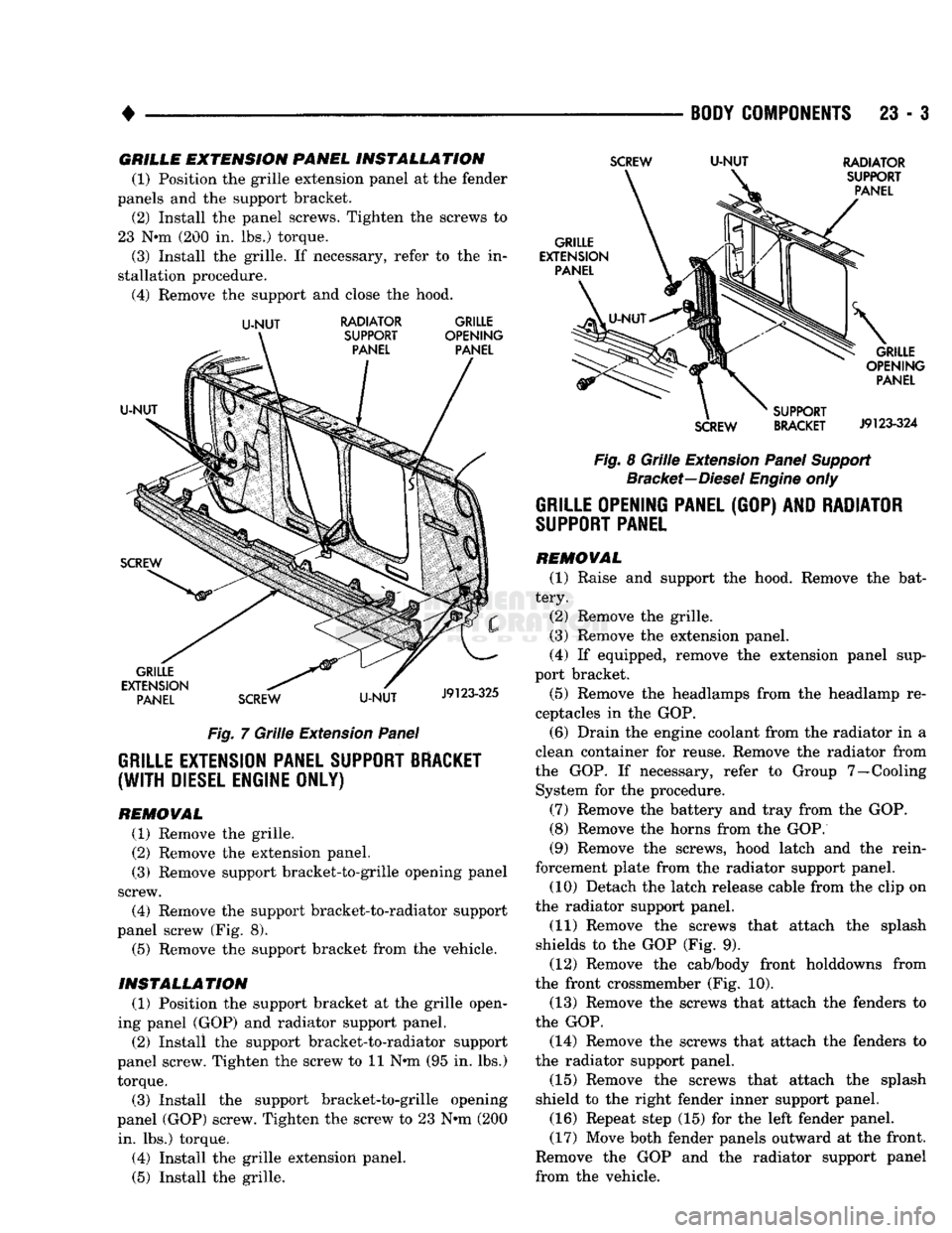
(1) Position the grille extension panel at the fender
panels and the support bracket. (2) Install the panel screws. Tighten the screws to
23 N*m (200 in. lbs.) torque.
(3) Install the grille. If necessary, refer to the in
stallation procedure. (4) Remove the support and close the hood.
U-NUT
RADIATOR GRILLE
Fig. 7 Grille Extension Panel
GRILLE EXTENSION PANEL SUPPORT BRACKET
(WITH
DIESEL ENGINE ONLY)
REMOWAL
(1) Remove the grille.
(2) Remove the extension panel.
(3) Remove support bracket-to-grille opening panel
screw. (4) Remove the support bracket-to-radiator support
panel screw (Fig. 8). (5) Remove the support bracket from the vehicle.
INSTALLATION
(1) Position the support bracket at the grille open
ing panel (GOP) and radiator support panel. (2) Install the support bracket-to-radiator support
panel screw. Tighten the screw to 11 N*m (95 in. lbs.) torque.
(3) Install the support bracket-to-grille opening
panel (GOP) screw. Tighten the screw to 23 N-m (200 in. lbs.) torque.
(4) Install the grille extension panel.
(5) Install the grille.
SCREW
U-NUT
RADIATOR
Fig. 8 Grille Extension Panel Support Bracket—Diesel Engine only
GRILLE OPENING PANEL
(GOP) AND
RADIATOR
SUPPORT
PANEL
REMOVAL
(1) Raise and support the hood. Remove the bat
tery. (2) Remove the grille.
(3) Remove the extension panel.
(4) If equipped, remove the extension panel sup
port bracket.
(5) Remove the headlamps from the headlamp re
ceptacles in the GOP.
(6) Drain the engine coolant from the radiator in a
clean container for reuse. Remove the radiator from
the GOP. If necessary, refer to Group 7—Cooling System for the procedure.
(7) Remove the battery and tray from the GOP.
(8) Remove the horns from the GOP.
(9) Remove the screws, hood latch and the rein
forcement plate from the radiator support panel. (10) Detach the latch release cable from the clip on
the radiator support panel.
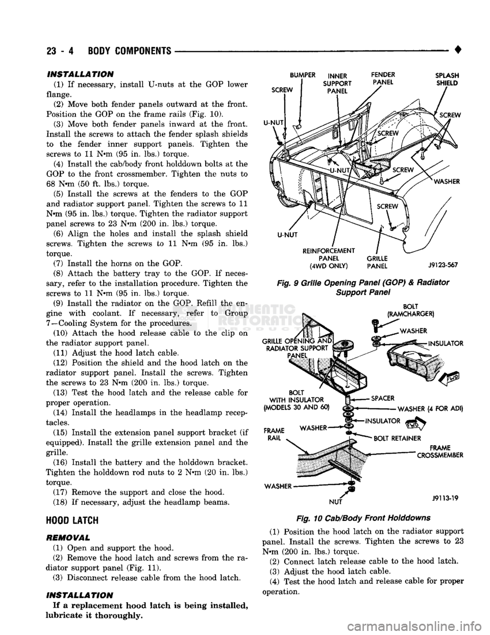
(11) Remove the screws that attach the splash
shields to the GOP (Fig. 9). (12) Remove the cab/body front holddowns from
the front crossmember (Fig. 10). (13) Remove the screws that attach the fenders to
the GOP.
(14) Remove the screws that attach the fenders to
the radiator support panel.
(15) Remove the screws that attach the splash
shield to the right fender inner support panel.
(16) Repeat step (15) for the left fender panel.
(17) Move both fender panels outward at the front.
Remove the GOP and the radiator support panel
from the vehicle.
Page 1387 of 1502
23
- 4
BODY
COMPONENTS
• INSTALLATION
(1) If necessary, install U-nuts at the GOP lower
flange. (2) Move both fender panels outward at the front.
Position the GOP on the frame rails (Fig. 10).
(3) Move both fender panels inward at the front.
Install the screws to attach the fender splash shields
to the fender inner support panels. Tighten the
screws to 11 N#m (95 in. lbs.) torque.
(4) Install the cab/body front holddown bolts at the
GOP to the front crossmember. Tighten the nuts to
68 Nnn (50 ft. lbs.) torque.
(5) Install the screws at the fenders to the GOP
and radiator support panel. Tighten the screws to 11
N»m (95 in. lbs.) torque. Tighten the radiator support
panel screws to 23 Nnn (200 in. lbs.) torque.
(6) Align the holes and install the splash shield
screws. Tighten the screws to 11 N»m (95 in. lbs.)
torque.
(7) Install the horns on the GOP.
(8) Attach the battery tray to the GOP. If neces
sary, refer to the installation procedure. Tighten the
screws to 11 Nnn (95 in. lbs.) torque.
(9) Install the radiator on the GOP. Refill the en
gine with coolant. If necessary, refer to Group 7—Cooling System for the procedures. (10) Attach the hood release cable to the clip on
the radiator support panel.
(11) Adjust the hood latch cable.
(12) Position the shield and the hood latch on the
radiator support panel. Install the screws. Tighten
the screws to 23 Nnn (200 in. lbs.) torque.
(13) Test the hood latch and the release cable for
proper operation.
(14) Install the headlamps in the headlamp recep
tacles.
(15) Install the extension panel support bracket (if
equipped). Install the grille extension panel and the
grille.
(16) Install the battery and the holddown bracket.
Tighten the holddown rod nuts to 2 Nnn (20 in. lbs.) torque.
(17) Remove the support and close the hood.
(18) If necessary, adjust the headlamp beams.
HOOD
LATCH
REMOVAL
(1) Open and support the hood.
(2) Remove the hood latch and screws from the ra
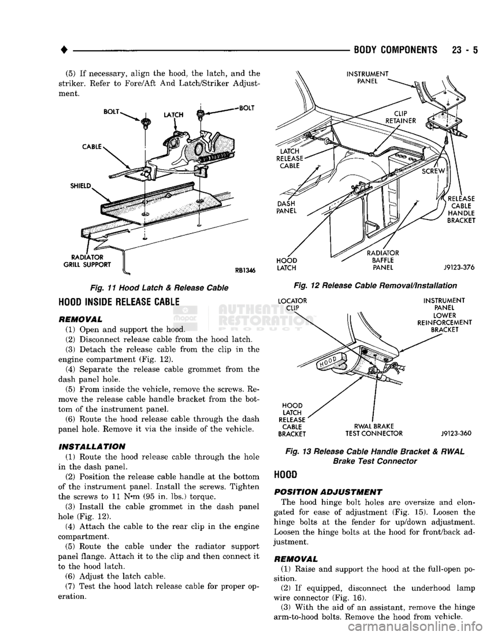
diator support panel (Fig. 11). (3) Disconnect release cable from the hood latch.
INSTALLATION If a replacement hood latch is being installed,
lubricate it thoroughly.
SCREW
U-NUT
BUMPER INNER FENDER
SUPPORT PANEL
PANEL
SPLASH
SHIELD
SCREW
U-NUT
REINFORCEMENT PANEL
(4WD
ONLY)
GRILLE
PANEL
J9123-567
Fig.
9
Grille
Opening
Panel
(GOP) & Radiator
Support
Panel
BOLT
(RAMCHARGER)
WASHER
GRILLE OPENING AND RADIATOR SUPPORT PANEL INSULATOR
BOLT
WITH
INSULATOR
(MODELS
30
AND
60)
FRAME
RAIL
WASHER NUT
SPACER
WASHER
(4
FOR ADI)
INSULATOR
^
BOLT
RETAINER
.
FRAME
— "
"
CROSSMEMBER
J9113-19
Fig.
10
Cab/Body
Front
Holddowns
(1) Position the hood latch on the radiator support
panel. Install the screws. Tighten the screws to 23 Nnn (200 in. lbs.) torque. (2) Connect latch release cable to the hood latch. (3) Adjust the hood latch cable.
(4) Test the hood latch and release cable for proper
operation.
Page 1388 of 1502
•
BODY
COMPONENTS
23 - 5
(5)
If
necessary, align
the
hood,
the
latch,
and the
striker. Refer
to
Fore/Aft
And
Latch/Striker Adjust
ment.
BOLT
CABLE
SHIELD
RADIATOR
GRILL SUPPORT
RB1346
Fig.
11
Hood
Latch
&
Release
Cable
HOOD
INSIDE
RELEASE
CABLE
REMOWAL
(1) Open
and
support
the
hood.
(2) Disconnect release cable from
the
hood latch.
(3) Detach
the
release cable from
the
clip
in the
engine compartment
(Fig. 12).
(4)
Separate
the
release cable grommet from
the
dash panel hole.
(5) From inside
the
vehicle, remove
the
screws.
Re
move
the
release cable handle bracket from
the
bot
tom
of the
instrument panel.
(6) Route
the
hood release cable through
the
dash
panel hole. Remove
it via the
inside
of the
vehicle.
INSTALLATION (1) Route
the
hood release cable through
the
hole
in
the
dash panel.
(2) Position
the
release cable handle
at the
bottom
of
the
instrument panel. Install
the
screws. Tighten
the screws
to 11 Nem (95 in. lbs.)
torque.
(3) Install
the
cable grommet
in the
dash panel
hole
(Fig. 12).
(4)
Attach
the
cable
to the
rear clip
in the
engine
compartment. (5) Route
the
cable under
the
radiator support
panel flange. Attach
it to the
clip
and
then connect
it
to
the
hood latch.
(6) Adjust
the
latch cable.
(7) Test
the
hood latch release cable
for
proper
op
eration.
RELEASE
CABLE
HANDLE
BRACKET
HOOD
LATCH
RADIATOR
BAFFLE PANEL
J9123-376
Fig.
12
Release
Cable Removal/Installation
LOCATOR
CLIP
HOOD
LATCH
RELEASE
CABLE
BRACKET
INSTRUMENT
PANEL
LOWER
REINFORCEMENT
BRACKET
RWAL BRAKE
TEST CONNECTOR
J9123-360
Fig.
13
Release
Cable Handle Bracket
&
RWAL
Brake
Test
Connector
HOOD
POSITION ADJUSTMENT The hood hinge bolt holes
are
oversize
and
elon
gated
for
ease
of
adjustment
(Fig. 15).
Loosen
the
hinge bolts
at the
fender
for
up/down adjustment.
Loosen
the
hinge bolts
at the
hood
for
front/back
ad
justment.
REMOVAL (1) Raise
and
support
the
hood
at the
full-open
po
sition. (2)
If
equipped, disconnect
the
underhood lamp
wire connector
(Fig. 16).
(3) With
the aid of an
assistant, remove
the
hinge
arm-to-hood bolts. Remove
the
hood from vehicle.
Page 1389 of 1502
23
- 6
BODY
COMPONENTS
•
INSTRUMENT
PANEL
COWL
PANEL
REGULATOR
BRACKET
J9123-437
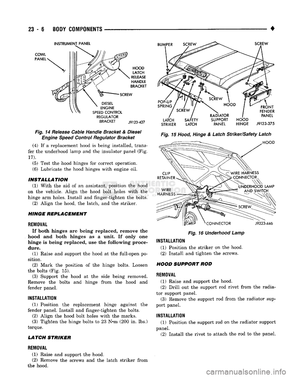
Fig.
14 Release Cable Handle Bracket &
Diesel
Engine
Speed
Control Regulator Bracket (4) If a replacement hood is being installed, trans
fer the underhood lamp and the insulator panel (Fig.
17).
(5) Test the hood hinges for correct operation.
(6) Lubricate the hood hinges with engine oil.
INSTALLATION
(1) With the aid of an assistant, position the hood
on the vehicle. Align the hood bolt holes with the
hinge arm holes. Install and finger-tighten the bolts. (2) Align the hood, the latch, and the striker.
HINGE
REPLACEMENT
REMOVAL
If both hinges are being replaced, remove the
hood and both hinges as a unit. If only one
hinge is being replaced, use the following proce dure. (1) Raise and support the hood at the full-open po
sition. (2) Mark the position of the hinge bolts. Loosen
the bolts (Fig. 15). (3) Support the hood at the side being removed.
Remove the bolts and hinge from the hood and
fender panel.
INSTALLATION
(1) Position the replacement hinge against the
fender panel. Install and finger-tighten the bolts. (2) Align the hood bolt holes with the marks.
(3) Tighten the hinge bolts to 23 N-m (200 in. lbs.)
torque.
LATCH STRIKER
LATCH SAFETY SUPPORT HOOD
STRIKER
LATCH PANEL HINGE
J9123-375
Fig.
16
Underhood
Lamp
INSTALLATION
(1) Position the striker on the hood.
(2) Install and tighten the screws.
HOOD SUPPORT ROD
REMOVAL
(1) Raise and support the hood.
(2) Drill out the support rod rivet from the radia
tor support panel. (3) Remove the support rod from the radiator sup
port panel.
INSTALLATION
(1) Position the support rod on the radiator support
panel. (2) Install the rivet to attach the rod to the panel.
REMOVAL
(1) Raise and support the hood.
(2) Remove the screws and the latch striker from
the hood.
Page 1447 of 1502
24 - 10
HEATING
AND AIR
CONDITIONING
•
(3) Add 50 ml (1.7 oz.) of clean refrigerant oil
through the suction port.
(4) Install compressor.
(5) Install the suction and discharge lines to the
compressor. Use new gaskets to prevent leakage.
Tighten the line nuts to 23 N*m (200 in. lbs.) torque.
(6)
Evacuate and charge system.
OVER-ALL
PERFORMANCE
TEST
Humidity has an important bearing on the temper
ature of the air delivered to the vehicle's interior.
This is true of all air conditioning systems It is im
portant to understand the effect humidity has on the
performance of the system. When humidity is high,
the evaporator has to perform a double duty. It must lower the air temperature and the temperature of the
moisture carried in the air. Condensing the moisture
in the air transfers a great deal of heat energy into
the evaporator fins and tubing. This reduces the amount of heat the evaporator can absorb from the
air.
Evaporator capacity used to reduce the amount of
moisture in the air is not wasted. Wringing some of
the moisture out of the air entering the vehicle adds
to the comfort of the passengers. However, an owner may expect too much from their air conditioning sys
tem on humid days. A performance test is the best
way to determine whether or not the system is per
forming up to standard. This test also provides valu able clues to the possible cause of trouble.
To perform the test the air temperature in the test
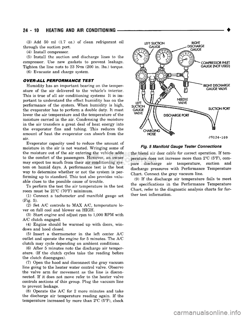
room must be 21°C (70°F) minimum. (1) Connect a tachometer and manifold gauge set
(Fig. 5).
(2) Set A/C controls to MAX A/C, temperature le
ver on full cool and blower on HIGH. (3) Start engine and adjust rpm to 1,000 RPM with
A/C clutch engaged.
(4) Engine should be warmed up with doors, win
dows and hood closed.
(5)
Insert a thermometer in the left center A/C
outlet and operate the engine for 5 minutes. The A/C
clutch may cycle depending on ambient conditions.
(6)
After 5 minutes note the discharge air temper
ature. (If the clutch cycles take the reading before
the clutch disengages).
(7) Open the hood and disconnect the gray vacuum
line going to the heater water control valve. Observe
the valve arm for movement as the line is discon nected. If it does not move refer to the heater valve
controls sections of this group. Plug the vacuum line
to prevent leakage.
(8) Operate the A/C for 2 more minutes and take
the discharge air temperature reading again. If the
temperature increased by more than 2°C (5°F), check
LEFT
SUCTION
RIGHT
J9124-109
Fig.
5 Manifold
Gauge
Tester
Connections
the blend air door cable for correct operation. If tem
perature does not increase more than 2°C
(5°F),
com
pare discharge air temperature, suction and discharge pressures with Performance Temperature Chart. Connect the gray vacuum line.
(9) If the discharge air temperature fails to meet
the specifications in the Performance Temperature Chart, refer to the diagnostic analysis charts for fur
ther test information.