1993 DODGE TRUCK tow
[x] Cancel search: towPage 219 of 1502
5
- 32
BRAKES
•
CALIPER
OVERHAUL
CALIPER DISASSEMBLY (1) Drain
old
fluid
out of
caliper.
(2)
Pad
outboard shoe side
of
caliper interior with
a minimum
2.54 cm (1 in.)
thickness
of
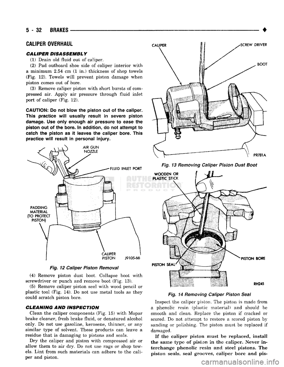
shop towels (Fig.
12).
Towels will prevent piston damage when
piston comes
out of
bore.
(3) Remove caliper piston with short bursts
of
com
pressed
air.
Apply
air
pressure through fluid inlet
port
of
caliper
(Fig. 12).
CAUTION:
Do
not
blow
the
piston
out of the
caliper.
This
practice
will
usually
result
in
severe piston
damage.
Use
only enough
air
pressure
to
ease
the
piston
out of the
bore.
In
addition,
do not
attempt
to
catch
the
piston
as it
leaves
the
caliper
bore. This
practice
will
result
in
personal
injury.
Fig.
12
Caliper Piston Removal
(4) Remove piston dust boot. Collapse boot with
screwdriver
or
punch
and
remove boot
(Fig. 13).
(5) Remove caliper piston seal with wood pencil
or
plastic tool
(Fig. 14). Do not use
metal tools
as
they could scratch piston bore.
CLEANING
AND
INSPECTION Clean
the
caliper components
(Fig. 15)
with Mopar
brake cleaner, fresh brake fluid,
or
denatured alcohol only.
Do not use
gasoline, kerosene, thinner,
or any
similar type
of
solvent. These products
can
leave
a
residue that
is
damaging
to
pistons
and
seals. Dry
the
caliper
and
piston with compressed
air or
allow them
to air dry. Do not use
rags
or
shop tow
els.
Lint from such materials
can
adhere
to the
cali
per
and
piston. Fig. 14 Removing Caliper Piston Seal
Inspect
the
caliper piston.
The
piston
is
made from
a phenolic resin (plastic material)
and
should
be
smooth
and
clean. Replace
the
piston
if
cracked
or
scored.
Do not
attempt
to
restore
a
scored piston
by
sanding
or
polishing.
The
piston must
be
replaced
if
damaged.
If
the
caliper piston must
be
replaced, install
the same
type
of
piston
in the
caliper.
Never
in
terchange phenolic resin
and
steel
pistons.
The
piston seals,
seal
grooves,
caliper bore
and pis-
Page 229 of 1502
5
- 42
BRAKES
•
CALIPER
DISASSEMBLY.
(1) Drain old fluid out of caliper.
(2) Pad outboard shoe side of caliper interior with
a minimum 2.54 cm (1 in.) thickness of shop towels
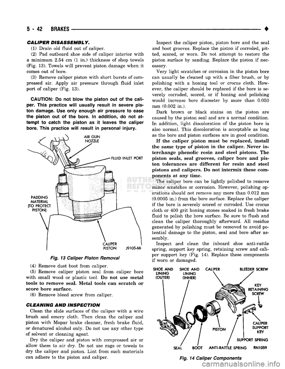
(Fig. 13). Towels will prevent piston damage when it
comes out of bore.
(3) Remove caliper piston with short bursts of com
pressed air. Apply air pressure through fluid inlet
port of caliper (Fig. 13).
CAUTION:
Do not
blow
the
piston
out of the
cali
per.
This
practice
will
usually
result
in
severe
pis
ton
damage.
Use only
enough
air
pressure
to
ease
the
piston
out of the
bore.
In
addition,
do not at
tempt
to catch the
piston
as it
leaves
the
caliper
bore.
This
practice
will
result
in
personal
injury.
PISTON
J9105-66
Fig.
13 Caliper
Piston
Removal (4) Remove dust boot from caliper.
(5) Remove caliper piston seal from caliper bore
with small wood or plastic tool. Do not use metal tools to remove seal. Metal tools can scratch or score bore surface. (6) Remove bleed screw from caliper.
CLEANING
AND INSPECTION Clean the slide surfaces of the caliper with a wire
brush and emery cloth. Then clean the caliper and
piston with Mopar brake cleaner, fresh brake fluid, or denatured alcohol only. Do not use any other type
of solvent or cleaning agent.
Dry the caliper and piston with compressed air or
allow them to air dry. Do not use rags or towels to
dry the caliper and piston. Lint from such materials
can adhere to the piston and caliper. Inspect the caliper piston, piston bore and the seal
and boot grooves. Replace the piston if corroded, pit
ted, scored, or worn. Do not attempt to restore the
piston surface by sanding. Replace the piston if nec essary.
Very light scratches or corrosion in the piston bore
can usually be cleaned up with a fiber brush, or by
polishing with a honing tool or crocus cloth. How ever, the caliper should be replaced if the bore is se
verely corroded, scored, or if honing and polishing
would increase bore diameter by more than 0.050
mm (0.002 in.).
Dark brown or black stains on the piston are
caused by the piston seal and are a normal condition.
In addition, light discoloration of the piston bore is also normal. This discoloration is acceptable as long as the bore and piston surfaces are in good condition.
If the caliper piston must be replaced, install
the same type of piston in the caliper. Never in
terchange phenolic resin and steel pistons. The piston seals, seal grooves, caliper bore and pis
ton tolerances are different for resin and steel
pistons and calipers. Do not intermix these com ponents at any time.
The caliper bore can be lightly polished to remove
minor scratches or corrosion. However, polishing op
erations should not remove any more than 0.012 mm (0.0005 in.) from the bore surface. Replace the caliper
if the bore is severely scored or corroded. Use crocus
cloth or 400 grit honing stones soaked in fresh brake
fluid to polish the bore surface. Be sure to flush and
clean the caliper thoroughly afterward. All residue generated by polishing must be removed to avoid po
tential damage to the piston, seal and bore after as sembly. Inspect and clean the inboard shoe anti-rattle
spring, support key spring, retaining screw and cali
per support key (Fig. 14). Replace these components if worn or damaged.
SHOE
AND
SHOE
AND
CALIPER
BLEEDER
SCREW
SEAL
BOOT
ANTI-RATTLE
SPRING
RN1059
Fig.
14 Caliper
Components
Page 236 of 1502
•
BRAKES
5 - 49 (2) Adjust brake shoes to drum with a brake
gauge. (3) Install and secure drum to wheel studs with
new retaining nuts/clips.
(4) Install rubber access plugs in support plate if
removed.
(5) Install wheel and tire.
BRAKE
SUPPORT PLATE REMOVAL
(1) Remove wheel and tire and brake drum.
(2) Remove axle shaft and retainer. Refer to Group
3 for procedures. (3) Remove primary brakeshoe for access to park
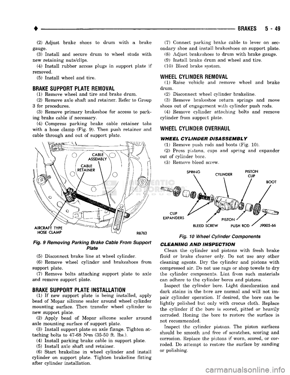
ing brake cable if necessary. (4) Compress parking brake cable retainer tabs
with a hose clamp (Fig. 9). Then push retainer and cable through and out of support plate.
AIRCRAFT TYPE
HOSE
CLAMP
RB763
Fig.
9
Removing
Parking Brake Cable From
Support
Plate
(5) Disconnect brake line at wheel cylinder.
(6) Remove wheel cylinder and brakeshoes from
support plate.
(7) Remove bolts attaching support plate to axle
and remove support plate.
BRAKE
SUPPORT PLATE INSTALLATION
(1) If new support plate is being installed, apply
bead of Mopar silicone sealer around wheel cylinder mounting surface. Then transfer wheel cylinder to
new support plate. (2) Apply bead of Mopar silicone sealer around
axle mounting surface of support plate. (3) Install support plate on axle flange. Tighten at
taching bolts to 47-68 N-m (35-50 ft. lbs.). (4) Install parking brake cable in support plate.
(5) Install axle shaft and retainer.
(6) Start brakeline in wheel cylinder and install
cylinder on support plate. Tighten brakeline fitting after cylinder installation. (7) Connect parking brake cable to lever on sec
ondary shoe and install brakeshoes on support plate.
(8) Adjust brakeshoes to drum with brake gauge.
(9) Install brake drum and wheel and tire.
(10) Bleed brake system.
WHEEL CYLINDER REMOVAL
(1) Raise vehicle and remove wheel and brake
drum. (2) Disconnect wheel cylinder brakeline.
(3) Remove brakeshoe return springs and move
shoes out of engagement with cylinder push rods. (4) Remove cylinder attaching bolts and remove
cylinder from support plate.
WHEEL
CYLINDER OVERHAUL
WHEEL
CYLINDER DISASSEMBLY
(1) Remove push rods and boots (Fig. 10).
(2) Press pistons, cups and spring and expander
out of cylinder bore.
(3) Remove bleed screw.
SPRING
CYLINDER PISTON
CUP
CUP
EXPANDERS
BOOT
PISTON
'
BLEED
SCREW PUSH
ROD '
J9005-66
Fig.
10
Wheel
Cylinder
Components
CLEANING
AND
INSPECTION
Clean the cylinder and pistons with fresh brake
fluid or brake cleaner only. Do not use any other cleaning agents. Dry the cylinder and pistons with
compressed air. Do not use rags or shop towels to dry
the cylinder components. Lint from such materials
can adhere to the cylinder bores and pistons.
Inspect the cylinder bore. Light discoloration and
dark stains in the bore are normal and will not im
pair cylinder operation. If desired, the bore can be lightly polished but only with crocus cloth. Replace
the cylinder if the bore is scored, pitted or heavily
corroded. Honing the bore to restore the surface is
not recommended.
Inspect the cylinder pistons. The piston surfaces
should be smooth and free of scratches, scoring and
corrosion. Replace the pistons if worn, scored, or cor
roded. Do attempt to restore the surface by sanding or polishing.
Page 237 of 1502
5
- 50
BRAKES
• Discard
the old
piston cups
and the
spring
and ex
pander. These parts
are not
reusable.
The
original
dust boots
may be
reused
but
only
if
they
are in
good condition.
ASSEMBLING
WHEEL
CYLINDER
(1) Lubricate wheel cylinder bore, pistons, piston
cups
and
spring
and
expander with clean brake fluid. (2) Install first piston
in
cylinder bore. Then
in
stall
cup in
bore
and
against piston.
Be
sure
lip of
piston
cup is
facing inward (toward spring
and
expander)
and
flat side
is
against piston.
(3) Install spring
and
expanders followed
by re
maining piston
cup and
piston.
(4) Install boots
on
each
end of
cylinder
and
insert
push rods
in
boots.
(5)
Install cylinder bleed screw.
WHEEL
CYLINDER INSTALLATION
(1) Apply bead
of
Mopar silicone sealer around cyl
inder mounting surface
of
support plate. (2) Connect brake line
to
cylinder. Mount cylinder
on support plate
and
install cylinder attaching bolts. (3) Install wheel brake components.
(4) Install brake drum
and
wheel
and
bleed
brakes.
DRUM
BRAKES—TWELVE INCH
INDEX
page
Brake Drum
Installation
54
Brake Drum Removal
52
Brake Drum Service
54
Brake
Shoe
Installation
53
Brakeshoe
Removal
52
Cleaning
and
Inspection
52
GENERAL
INFORMATION
Twelve inch rear drum brakes
are
used
on D and
W 250/350 models
(Fig. 1). All
applications
are
dual
shoe,
internal expanding units with
a
self adjusting
mechanism.
A
single wheel cylinder
is
used
to ex-
page
General
Information
50
Support
Plate
Installation
55
Support
Plate
Removal
55
Wheel
Cylinder
Installation
55
Wheel
Cylinder
Overhaul
...................
54
Wheel
Cylinder
Removal
. 54
pand
the
dual brakeshoes.
The
lower ends
of the
brake shoes
are
connected
by a
star wheel adjuster screw which
is
part
of the
self adjusting mechanism
(Fig.
1).
Page 241 of 1502
5
- 54
BRAKES
• (11) Attach adjuster cable to adjuster lever. Be
sure cable is properly routed.
(12) Adjust brakeshoes to drum with brake gauge.
BRAKE
DRUM INSTALLATION
(1) Position drum on axle housing.
(2) Install bearing and inner nut. Adjust bearing
as described in Group 3. (3) Install locking washer and outer nut. Bend
locking washer to secure it. (4) Place new gasket on hub and install axle shaft,
cones,
lock washers and nuts. (5) Install wheel and tire assembly.
(6) Remove support stands and lower vehicle.
BRAKE
DRUM
SERVICE
BRAKE DRUM REFINISHING The brake drums can be resurfaced on a drum
lathe when necessary. Initial machining cuts should
be limited to 0.12 - 0.20 mm (0.005 - 0.008 in.) at a time as heavier feed rates can produce taper and sur
face variation. Final finish cuts of 0.025 to 0.38 mm (0.001 to 0.0015 in) are recommended and will gen
erally provide the best surface finish.
Be sure the drum is securely mounted in the lathe
before machining operations. A damper strap should always be used around the drum to reduce vibration
and avoid chatter marks.
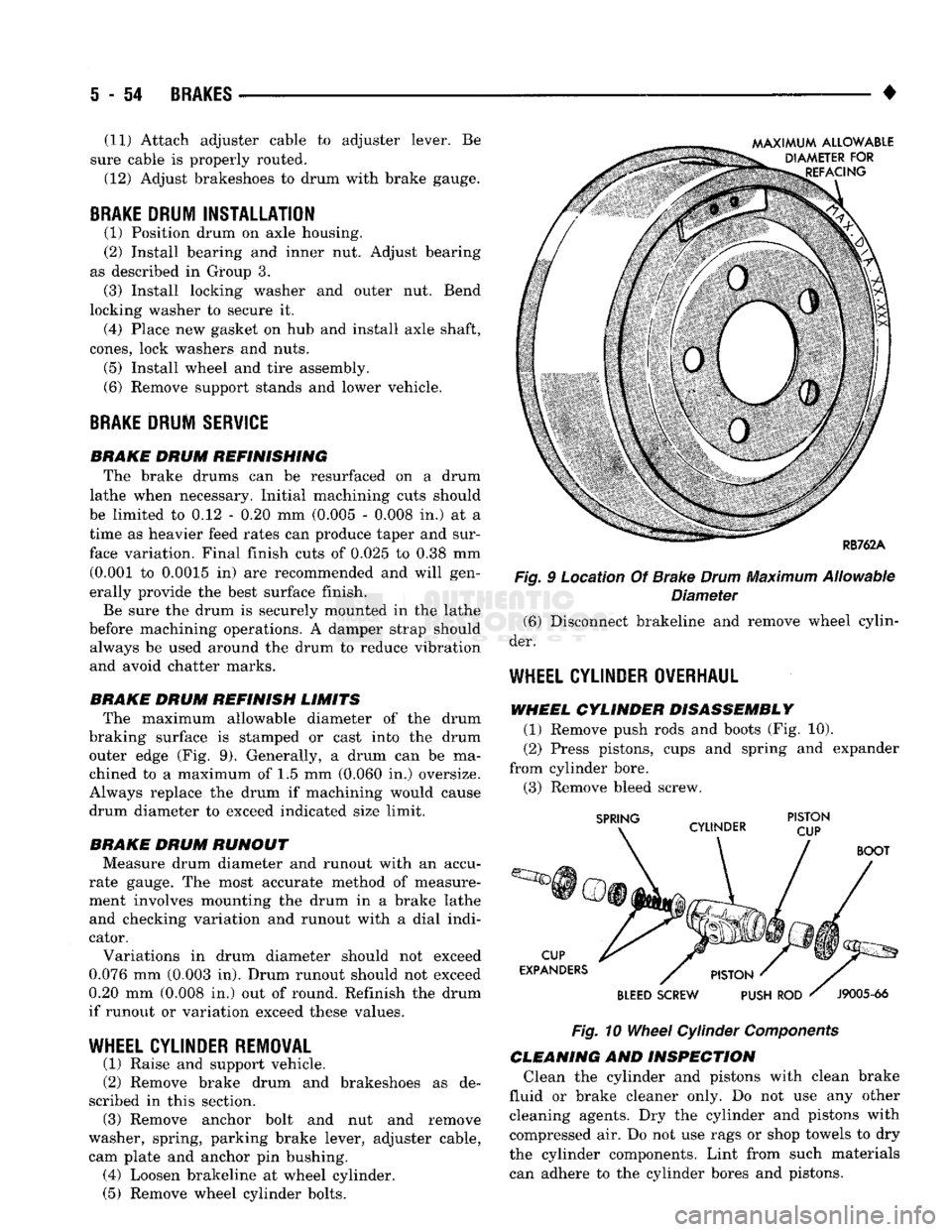
BRAKE DRUM REFINISH LIMITS The maximum allowable diameter of the drum
braking surface is stamped or cast into the drum outer edge (Fig. 9). Generally, a drum can be ma
chined to a maximum of 1.5 mm (0.060 in.) oversize.
Always replace the drum if machining would cause
drum diameter to exceed indicated size limit.
BRAKE DRUM RUNOUT Measure drum diameter and runout with an accu
rate gauge. The most accurate method of measure
ment involves mounting the drum in a brake lathe and checking variation and runout with a dial indi
cator.
Variations in drum diameter should not exceed
0.076 mm (0.003 in). Drum runout should not exceed
0.20 mm (0.008 in.) out of round. Refinish the drum
if runout or variation exceed these values.
WHEEL
CYLINDER REMOVAL
(1) Raise and support vehicle.
(2) Remove brake drum and brakeshoes as de
scribed in this section. (3) Remove anchor bolt and nut and remove
washer, spring, parking brake lever, adjuster cable, cam plate and anchor pin bushing. (4) Loosen brakeline at wheel cylinder.
(5) Remove wheel cylinder bolts. Fig. 9 Location Of Brake
Drum
Maximum Allowable
Diameter (6) Disconnect brakeline and remove wheel cylin
der.
WHEEL
CYLINDER OVERHAUL
WHEEL CYLINDER DISASSEMBLY (1) Remove push rods and boots (Fig. 10).
(2) Press pistons, cups and spring and expander
from cylinder bore. (3) Remove bleed screw.
Fig.
10
Wheel
Cylinder
Components
CLEANING AND INSPECTION Clean the cylinder and pistons with clean brake
fluid or brake cleaner only. Do not use any other cleaning agents. Dry the cylinder and pistons with
compressed air. Do not use rags or shop towels to dry
the cylinder components. Lint from such materials can adhere to the cylinder bores and pistons.
Page 242 of 1502
•
BRAKES
5 - 55 Inspect the cylinder bore. Light discoloration and
dark stains in the bore are normal and will not im
pair cylinder operation. If desired, the bore can be lightly polished but only with crocus cloth. Replace
the cylinder if the bore is scored, pitted or heavily corroded. Honing the bore to restore the surface is not recommended.
Inspect the cylinder pistons. The piston surfaces
should be smooth and free of scratches, scoring and
corrosion. Replace the pistons if worn, scored, or cor
roded. Do attempt to restore the surface by sanding or polishing.
Discard the old piston cups and the spring and ex
pander. These parts are not reusable. The original
dust boots may be reused but only if they are in good condition.
ASSEMBLING
WHEEL CYLINDER
(1) Lubricate wheel cylinder bore, pistons, piston
cups and spring and expander with ^clean brake fluid. (2) Install first piston in cylinder bore. Then in
stall cup in bore and against piston. Be sure lip of
piston cup is facing inward (toward spring and
expander) and flat side is against piston.
(3) Install spring and expanders followed by re
maining piston cup and piston.
(4) Install boots on each end of cylinder and insert
push rods in boots.
(5)
Install cylinder bleed screw.
WHEEL
CYLINDER INSTALLATION
(1) Start brakeline into cylinder.
(2) Position cylinder on support plate and install
cylinder attaching bolts. (3) Tighten brakeline fitting and cylinder attach
ing bolts. (4) Install anchor pin bushing, cam plate, adjuster
cable, parking brake lever, spring washer and anchor
bolt and nut.
(5) Install brakeshoes and brake drum as described
in this section. (6) Install axle shaft.
(7) Install wheel and tire.
(8) Remove supports and lower vehicle.
SUPPORT
PLATE REMOVAL
(1) Raise and support vehicle.
(2) Remove wheel and tire.
(3) Remove axle shaft.
(4) Remove brake drum, brake shoes and wheel
cylinder as described in this section. (5) Remove bolts/nuts attaching support plate to
axle and remove support plate.
SUPPORT PLATE INSTALLATION
(1) Transfer wheel cylinder and parking brake le
ver components to replacement support plate. (2) Position support plate on axle and install at
taching bolts/nuts. (3) Lubricate shoe contact surfaces of support plate
with Mopar multi-purpose, or high temperature bear ing grease. (4) Install brakeshoes. Adjust shoes to drum with
brake gauge. (5) Install brake drum.
(6) Install axle shaft.
(7) Install wheel and tire.
(8) Remove supports and lower vehicle.
Page 256 of 1502
•
CLUTCH
6 - 3 Check condition of the clutch before installation. A
warped cover or diaphragm spring will cause grab and incomplete release or engagement.
Be careful when handling the cover and disc. Im
pact can distort the cover, diaphragm spring, release
fingers and the hub of the clutch disc.
Use an alignment tool when positioning the disc on
the flywheel. The tool prevents accidental misalign ment which could result in cover distortion and disc
damage.
A frequent cause of clutch cover distortion (and
consequent misalignment) is improper bolt tighten
ing. To avoid warping the cover, tighten the bolts al
ternately (in a diagonal pattern) and evenly (2-3
threads at a time) to specified torque.
Clutch
Housing
Misalignment And Runout Clutch housing alignment is important to proper
operation. The housing bore maintains alignment be
tween the crankshaft and transmission input shaft.
Misalignment can cause noise, incomplete clutch
release and chatter. It can also result in premature
wear of the pilot bearing, cover release fingers and
clutch disc. In severe cases, misalignment can also cause premature wear of the transmission input
shaft and bearing.
Housing face misalignment is generally caused by
incorrect seating on the engine or transmission, loose
housing bolts, missing alignment dowels or housing damage. Infrequently, misalignment may also be
caused by housing mounting surfaces that are not
parallel. If housing misalignment is suspected, housing bore
and face runout can be checked with a dial indicator
as described in the following two procedures:
MEASURING
CLUTCH HOUSING BORE
RUNOUT
(1) Remove the clutch housing and strut.
(2) Remove the clutch cover and disc.
(3) Replace one of the flywheel bolts with a 7/16-20
threaded rod that is 10 in. (25.4 cm) long (Fig. 1).
The rod will be used to mount the dial indicator.
(4) Remove the release fork from the clutch hous
ing. (5) Reinstall the clutch housing. Tighten the hous
ing bolts nearest the alignment dowels first. (6) Mount the dial indicator on the threaded rod
and position the indicator plunger on the surface of
the clutch housing bore (Fig. 2).
(7) Rotate the crankshaft until the indicator
plunger is at the top center of the housing bore. Zero the indicator at this point.
(8) Rotate the crankshaft and record the indicator
readings at eight points (45° apart) around the bore (Fig. 3). Repeat the measurement at least twice for
accuracy. (9) Subtract each reading from the one 180° oppo
site to determine magnitude and direction of runout.
Refer to Figure 3 and following example.
Bore runout example: 0.000 - (-0.007) = 0.007 in. + 0.002 - (-0.010) = 0.012 in.
+ 0.004 - (-0.005) = 0.009 in.
-0.001 -
(
+ 0.001) = -0.002 in. (= 0.002 inch)
In the above example, the largest difference is
0.012 in. and is called the total indicator reading
(TIR).
This means that the housing bore is offset
from the crankshaft centerline by 0.006 in. (which is 1/2 of 0.012 in.).
On gas engines, the acceptable maximum TIR for
housing bore runout is 0.010 inch. If measured TIR is more than 0.010 in. (as in the example), bore runout
will have to be corrected with offset dowels. Offset dowels are available in 0.007, 0.014 and 0.021 in.
sizes for this purpose (Fig. 4). Refer to Correcting
Housing Bore Runout for dowel installation.
On diesel engines, the acceptable maximum
TIR for housing bore runout is 0.015 inch. How
ever, unlike gas engines, offset dowels are not available to correct runout on diesel engines. If
bore runout exceeds the stated maximum on a diesel engine, it may be necessary to replace ei
ther the clutch housing, or transmission adapter
plate.
CORRECTING CLUTCH HOUSING BORE
RUNOUT
(GAS
ENGINE
ONLY)
On gas engine vehicles, clutch housing bore runout
is corrected with offset dowels. However, if bore
runout exceeds 0.015 in. TIR on a diesel equipped model, the clutch housing, or transmission adapter
plate may have to be replaced. Offset dowels are not available for diesel models.
The dial indicator reads positive when the plunger
moves inward (toward indicator) and negative when it moves outward (away from indicator). As a result,
the lowest or most negative reading determines the
direction of housing bore offset (runout).
In the sample readings shown in Figure 3 and in
step (7) above, the bore is offset toward the 0.010
inch reading. To correct this, remove the housing and
original dowels. Then install the new offset dowels in
the direction needed to center the bore with the crankshaft centerline.
In the example, TIR was 0.012 inch. The dowels
needed for correction would have an offset of 0.007
in. (Fig. 4).
Install the dowels with the slotted side facing out
so they can be turned with a screwdriver. Then in
stall the housing, remount the dial indicator and
check bore runout again. Rotate the dowels until the
TIR is less than 0.010 in. if necessary.
If a TIR of 0.053 in. or greater is encountered, it
may be necessary to replace the clutch housing.
Page 259 of 1502
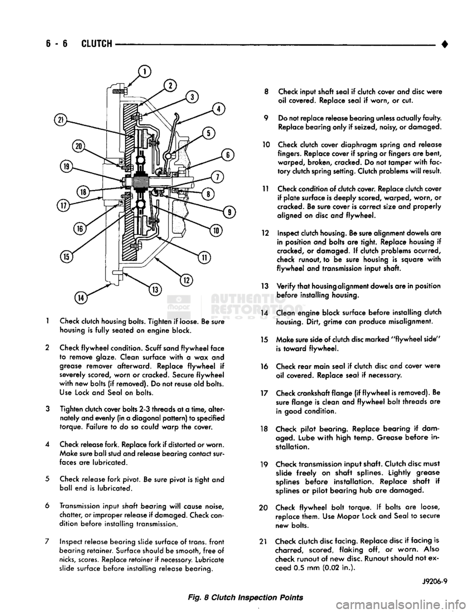
6 - 6
CLUTCH
1
Check
clutch
housing bolts.
Tighten
if loose. Be sure
housing
is
fully
seated on engine block.
2 Check
flywheel
condition.
Scuff sand
flywheel
face
to remove glaze. Clean surface
with
a wax and
grease
remover afterward. Replace
flywheel
if
severely scored, worn or cracked. Secure
flywheel
with
new bolts (if removed). Do not reuse old bolts.
Use
Lock and Seal on bolts.
3
Tighten clutch cover bolts 2-3 threads at a
time,
alter
nately and evenly (in a diagonal
pattern)
to specified
torque. Failure to do so could warp the cover.
4 Check release fork. Replace fork if distorted or worn. Make sure ball stud and release bearing contact sur
faces
are lubricated.
5
Check release fork pivot. Be sure pivot is tight and ball end is lubricated.
6 Transmission input
shaft
bearing
will
cause noise,
chatter,
or improper release if
damaged.
Check
con
dition before installing transmission.
7 Inspect release bearing slide surface of trans,
front
bearing
retainer.
Surface should be smooth,
free
of
nicks,
scores.
Replace
retainer
if
necessary.
Lubricate slide surface before installing release bearing. 8 Check input shaft seal if clutch cover and
disc
were
oil covered. Replace seal if worn, or cut.
9 Do not replace release bearing
unless
actually
faulty.
Replace bearing only if seized, noisy, or damaged.
10 Check clutch cover diaphragm spring and release
fingers.
Replace cover if spring or fingers are bent, warped, broken, cracked. Do not tamper
with
fac
tory
clutch spring setting. Clutch problems
will
result.
11 Check condition of clutch cover. Replace clutch cover if
plate
surface is deeply scored, warped, worn, or
cracked. Be sure cover is correct size and properly
aligned on
disc
and flywheel.
12 Inspect clutch
housing.
Be sure alignment dowels are in position and bolts are tight. Replace housing if
cracked, or damaged. If clutch problems ocurred,
check runout, to be sure housing is square
with
flywheel
and transmission input shaft.
13
Verify
that
housing
alignment dowels are in position before installing
housing.
14 Clean engine block surface before installing clutch
housing.
Dirt, grime can produce misalignment.
15 Make sure side of clutch
disc
marked
"flywheel
side"
is
toward flywheel.
16 Check
rear
main seal if clutch
disc
and cover
were
oil covered. Replace seal if necessary.
17 Check crankshaft flange (if
flywheel
is removed). Be sure flange is clean and
flywheel
bolt threads are
in
good
condition.
18 Check pilot bearing. Replace bearing if dam
aged.
Lube
with
high temp. Grease before in
stallation.
19 Check transmission input shaft. Clutch
disc
must slide
freely
on shaft splines. Lightly grease
splines
before installation. Replace shaft if
splines
or pilot bearing hub are damaged.
20 Check
flywheel
bolt torque. If bolts are loose, replace them. Use Mopar Lock and Seal to secure
new bolts.
21 Check clutch
disc
facing. Replace
disc
if facing is charred, scored, flaking off, or worn.
Also
check runout of new
disc.
Runout should not ex
ceed 0.5 mm (0.02 in.).
J9206-9
Fig. 8 Clutch Inspection Points