1993 DODGE TRUCK tow
[x] Cancel search: towPage 457 of 1502
8N
- 2
REAR WINDOW DEFOGGER
• (b) Rear window grid lines (all grid lines would
have to be broken) or one of the feed wires are not
connected for the system to be inoperative.
The following paragraphs outline component check
out procedures.
If turning the switch ON produces severe voltmeter
deflection, the circuit should be closely checked for a shorting condition. If system operation has been verified but indicator
bulb does not light, check and replace bulb.
For detailed wiring information, refer to Group 8W
- Wiring Diagrams.
REAR
WINDOW GRID LINES TEST
Horizontal grid lines and vertical bus bar lines
printed and baked on inside surface of rear window glass (Fig. 1) comprise an electrical parallel circuit.
The electrically conductive lines are made of a silver- ceramic material. When baked onto glass they be
come bonded to the glass and are highly resistant to abrasion. It is possible, however, that a break may
exist or occur in an individual grid line resulting in
no current flow through the line. To detect breaks in
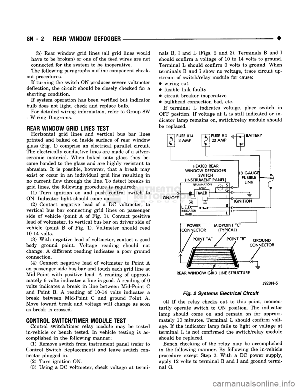
grid lines, the following procedure is required: (1) Turn ignition on and push control switch to
ON. Indicator light should come on. (2) Contact negative lead of a DC voltmeter, to
vertical bus bar connecting grid lines on passenger side of vehicle (point A of Fig. 1). Contact positive
lead of voltmeter, to vertical bus bar on driver side of
vehicle (point B of Fig. 1). Voltmeter should read 10-14 volts. (3) With negative lead of voltmeter, contact a good
body ground point. Voltage reading should not change. A different reading indicates a poor ground connection. (4) Connect negative lead of voltmeter to Point A
on passenger side bus bar and touch each grid line at
Mid-Point with positive lead. A reading of approxi mately 6 volts indicates a line is good. A reading of 0
volts indicates a break in line between Mid-Point C and Point B. A reading of 10-14 volts indicates a
break between Mid-Point C and ground Point A. Move toward break and voltage will change as soon as break is crossed.
CONTROL SWITCH/TIMER MODULE TEST
Control switch/timer relay module may be tested
in-vehicle or bench tested. In vehicle testing is ac
complished in the following manner: (1) Remove switch from instrument panel (refer to
Control Switch Replacement) and leave switch con
nector plugged in. (2) Turn ignition ON.
(3) Using a DC voltmeter, check voltage at termi nals B, I and L (Figs. 2 and 3). Terminals B and I
should confirm a voltage of 10 to 14 volts to ground.
Terminal L should confirm 0 volts to ground. When terminals B and I show no voltage, trace circuit up
stream of switch/relay module for cause:
• wiring cut
• fusible link faulty
• circuit breaker inoperative
• bulkhead connection bad, etc. If terminal L indicates voltage, place switch in
OFF position. If voltage at L is still indicated or in
dicator lamp remains on, switch/relay module should
be replaced.
"XI
FUSE
#14
rr~
P 3
AAAP
P
FUSE
#3
20
AAAP
BATTERY
HEATED
REAR
WINDOW
DEFOGGER
SWITCH
(INSTRUMENT
PANEL)
ON/OFF
ILLUMINATION
LAMP
fez TIMER
L.E.I
INDICATOR
LIGHT
-©-
18
GAUGE
FUSIBLE
LINK
IGNITION POWER
MIDPOINT
"C"
CONNECTOR (TYPICAL)
POINT
"A"
POINT
"B"
GROUND
CONNECTOR
REAR
WINDOW
GRID
LINE
STRUCTURE
Fig.
2
Systems
Electrical Circuit
J928N-5
(4) If the relay checks out to this point, momen
tarily operate switch to ON position. The indicator lamp should come on and remain on for approxi
mately 10 minutes. Terminal L should confirm volt
age.
If the indicator lamp fails to light or voltage at
terminal L is not confirmed the switch/relay module should be replaced.
Bench checking of the relay may be accomplished
in the following manner. By following the in-vehicle
procedure except Step 2: With a DC power supply, apply 12 volts to terminal B and I and ground termi
nal G.
Page 464 of 1502
•
POWER
WINDOWS
8S - 3
FROM PIN
SIDE
OF
SWITCH
MASTER
WINDOW
LIFT
SWITCH
SWITCH
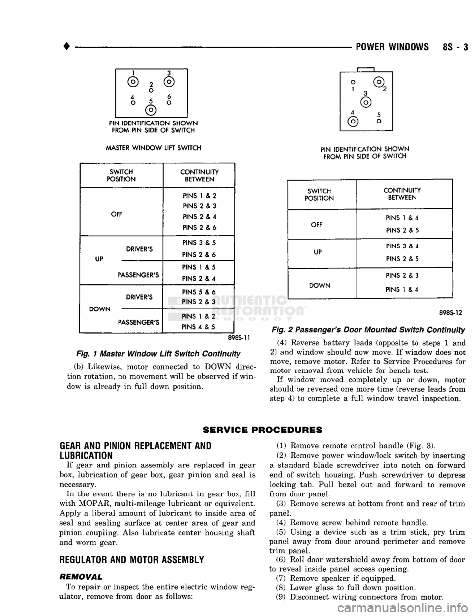
POSITION CONTINUITY
BETWEEN
OFF
PINS
1 & 2
PINS
2 & 3
PINS
2 &4
PINS
2 & 6
DRIVER'S
MP
PINS
3 & 5
PINS
2 & 6
PASSENGER'S
PINS
1 & 5
PINS
2 &4
DRIVER'S
PINS
5 & 6
PINS
2 & 3
TOWN
PASSENGER'S
PINS
1 & 2
PINS
4 & 5 898S-11
Fig.
1 Master Window
Lift
Switch
Continuity
(b) Likewise, motor connected to DOWN direc
tion rotation, no movement will be observed if win
dow is already in full down position.
PIN IDENTIFICATION SHOWN
FROM
PIN
SIDE
OF
SWITCH
SWITCH CONTINUITY
POSITION
BETWEEN
PINS
1 & 4
OFF
PINS
2 & 5
PINS
3 & 4
UP
PINS
2 & 5
PINS
2 & 3
DOWN
PINS
1 & 4
898S-12
Fig.
2
Passenger's Door
Mounted
Switch
Continuity
(4) Reverse battery leads (opposite to steps 1 and
2) and window should now move. If window does not
move, remove motor. Refer to Service Procedures for
motor removal from vehicle for bench test.
If window moved completely up or down, motor
should be reversed one more time (reverse leads from
step 4) to complete a full window travel inspection.
SERVICE
PROCEDURES
GEAR
AND PINION
REPLACEMENT
AND
LUBRICATION
If gear and pinion assembly are replaced in gear
box, lubrication of gear box, gear pinion and seal is necessary. In the event there is no lubricant in gear box, fill
with MOPAR, multi-mileage lubricant or equivalent. Apply a liberal amount of lubricant to inside area of seal and sealing surface at center area of gear and
pinion coupling. Also lubricate center housing shaft and worm gear.
REGULATOR
AND
MOTOR
ASSEMBLY
REMOVAL To repair or inspect the entire electric window reg
ulator, remove from door as follows: (1) Remove remote control handle (Fig. 3).
(2) Remove power window/lock switch by inserting
a standard blade screwdriver into notch on forward
end of switch housing. Push screwdriver to depress
locking tab. Pull bezel out and forward to remove
from door panel.
(3) Remove screws at bottom front and rear of trim
panel.
(4) Remove screw behind remote handle.
(5)
Using a device such as a trim stick, pry trim
panel away from door around perimeter and remove
trim panel. (6) Roll door watershield away from bottom of door
to reveal inside panel access opening. (7) Remove speaker if equipped.
(8) Lower glass to full down position.
(9) Disconnect wiring connectors from motor.
Page 475 of 1502
8U
- 4
CHIME/BUZZER WARNING
SYSTEMS
•
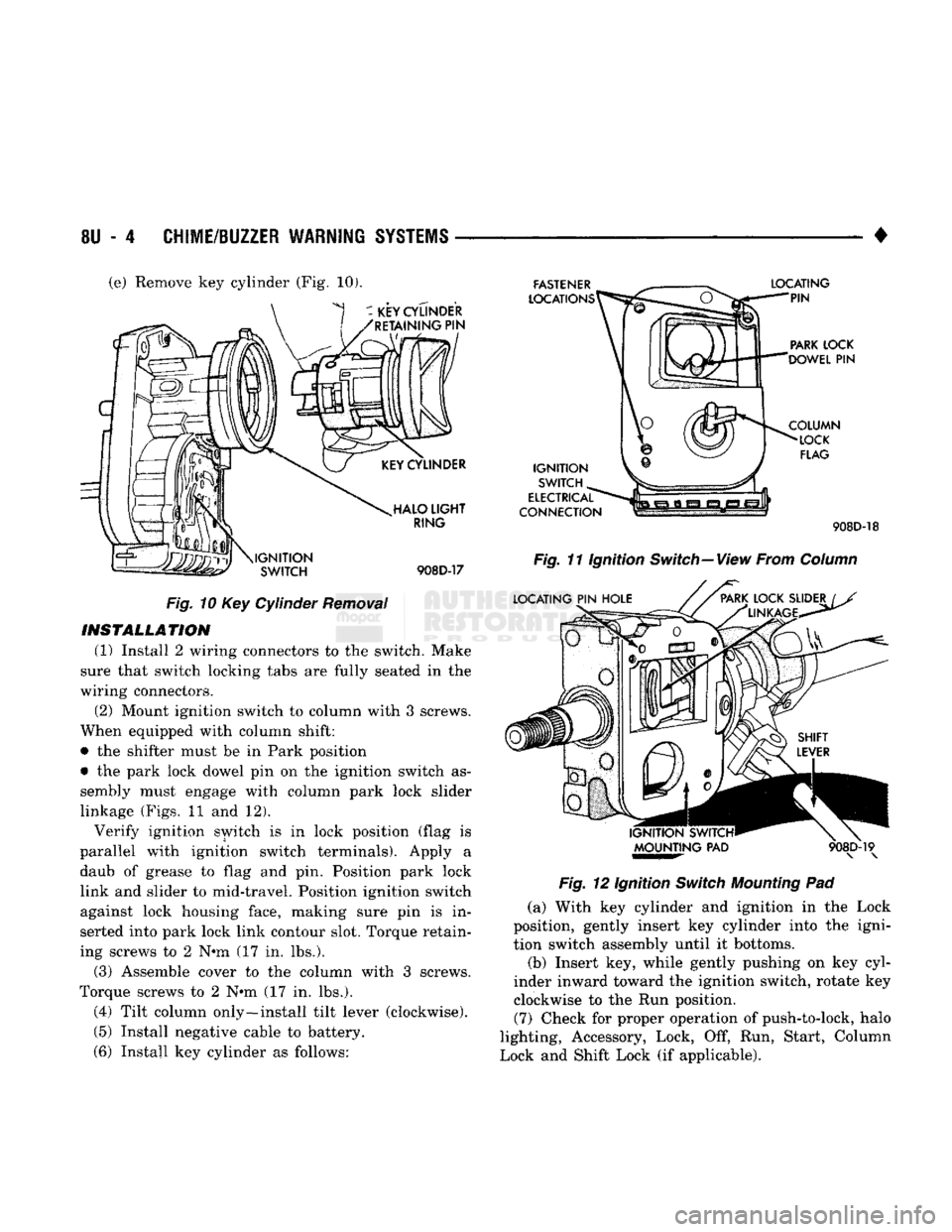
(e) Remove key cylinder (Fig, 10).
Fig.
10 Key Cylinder
Removal
INSTALLATION
(1) Install 2 wiring connectors to the switch. Make
sure that switch locking tabs are fully seated in the
wiring connectors.
(2) Mount ignition switch to column with 3 screws.
When equipped with column shift:
• the shifter must be in Park position
• the park lock dowel pin on the ignition switch as
sembly must engage with column park lock slider
linkage (Figs. 11 and 12). Verify ignition switch is in lock position (flag is
parallel with ignition switch terminals). Apply a daub of grease to flag and pin. Position park lock link and slider to mid-travel. Position ignition switch
against lock housing face, making sure pin is in
serted into park lock link contour slot. Torque retain
ing screws to 2 N*m (17 in. lbs.).
(3) Assemble cover to the column with 3 screws.
Torque screws to 2 N*m (17 in. lbs.).
(4) Tilt column only—install tilt lever (clockwise). (5) Install negative cable to battery.
(6) Install key cylinder as follows: 908D-18
Fig.
11 Ignition Switch—View From
Column
Fig.
12 Ignition
Switch
Mounting
Pad
(a) With key cylinder and ignition in the Lock
position, gently insert key cylinder into the igni
tion switch assembly until it bottoms.
(b) Insert key, while gently pushing on key cyl
inder inward toward the ignition switch, rotate key clockwise to the Run position. (7) Check for proper operation of push-to-lock, halo
lighting, Accessory, Lock, Off, Run, Start, Column
Lock and Shift Lock (if applicable).
Page 516 of 1502
WIRING
DIAGRAMS
SW - 41
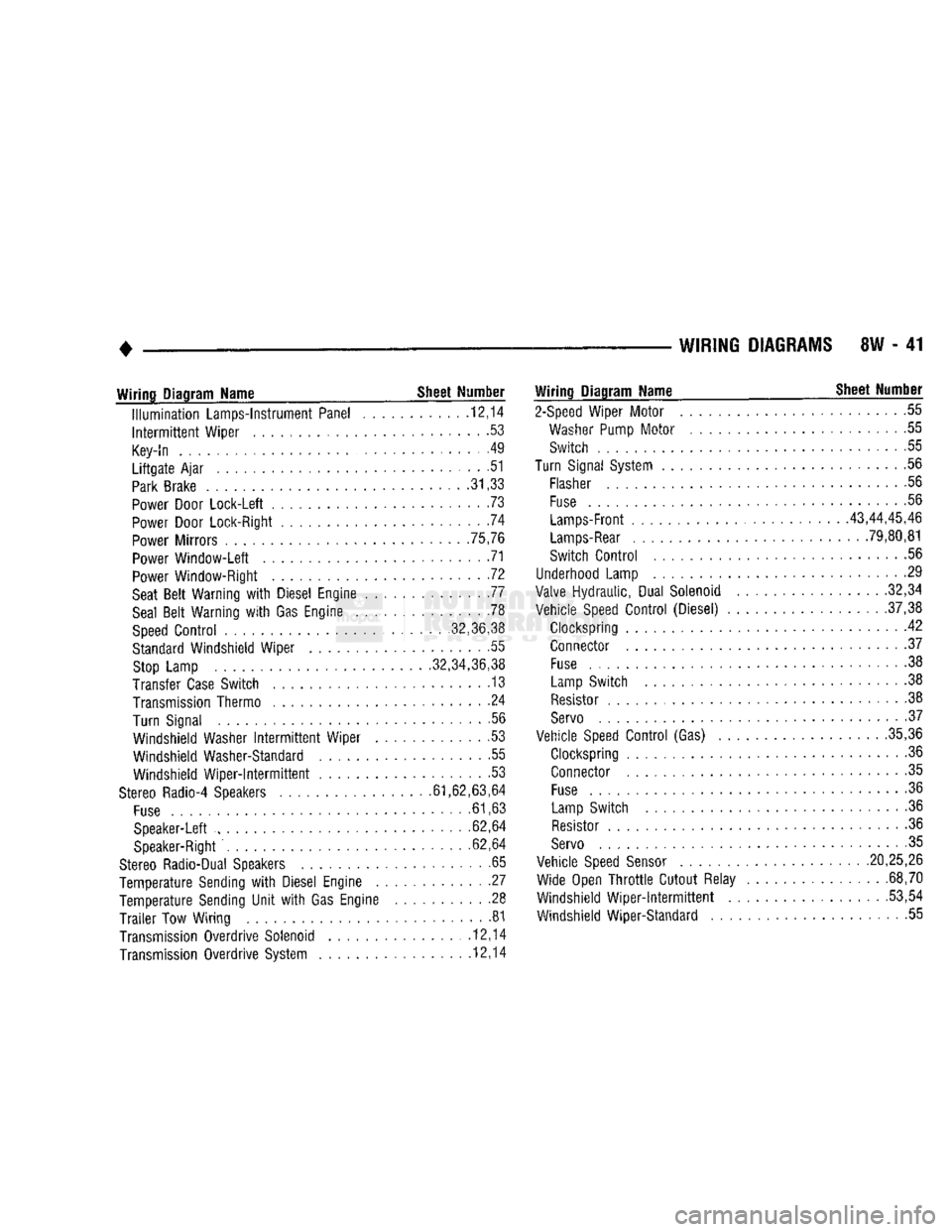
Wiring
Diagram Name _ Sheet Number
Illumination
Lamps-Instrument Panel ........... .12,14
Intermittent
Wiper ......................... .53
Key-In
. . . . . . . .49
Liftgate
Ajar
............................ .51
Park
Brake
.31,33
Power
Door Lock-Left ....................... .73
Power
Door Lock-Right .74
Power
Mirrors .75,76
Power
Window-Left 71
Power
Window-Right . .72
Seat
Belt
Warning
with
Diesel Engine 77
Seal
Belt
Warning
with
Gas Engine .78
Speed
Control
........... ,32,36,38
Standard
Windshield Wiper . .55
Stop
Lamp .32,34,36,38
Transfer
Case
Switch . 13
Transmission
Thermo ....................... .24
Turn Signal .56
Windshield Washer
Intermittent
Wiper . .53
Windshield Washer-Standard .55 Windshield
Wiper-Intermittent
53
Stereo
Radio-4 Speakers .61,62,63,64
Fuse
.61,63
Speaker-Left ......... ............ 62,64
Speaker-Right
. .62,64
Stereo
Radio-Dual Speakers .65
Temperature Sending
with
Diesel Engine . .27
Temperature Sending
Unit
with
Gas Engine .......... .28
Trailer
Tow Wiring 81
Transmission
Overdrive Solenoid ............... .12,14
Transmission
Overdrive System 12,14
Wiring
Diagram Name ^ Sheet Number
2-Speed
Wiper Motor 55
Washer
Pump
Motor
....................... .55
Switch 55
Turn
Signal
System
.......................... .56
Flasher
56
Fuse
.56
Lamps-Front
43,44,45,46
Lamps-Rear
. 79,80,81
Switch
Control
56
Underhood
Lamp 29
Valve
Hydraulic, Dual Solenoid .32,34
Vehicle
Speed
Control
(Diesel) .37,38
Clockspring 42 Connector .37
Fuse
................................. .38
Lamp
Switch . . .38
Resistor
.38
Servo
• .37
Vehicle
Speed
Control
(Gas) .35,36
Clockspring 36
Connector .35
Fuse
......... 36
Lamp
Switch .36
Resistor
.36
Servo
. 35
Vehicle
Speed
Sensor
.20,25,26 Wide Open
Throttle
Cutout Relay . .68,70
Windshield
Wiper-intermittent
...... ....... .53,54
Windshield Wiper-Standard 55
Page 597 of 1502
SW - 122
WIRING
DIAGRAMS
PART OF
CHASSIS
WIRING
(SEE
SH 80) Zl 18BK-
f~L7 18BK/YL•
5~L62 18BR/RD
5—L1 18VT/BK- 1
OO -L7 18BK/YL-
-D7 18BK/LG—
X2
18GY- X2 18GY- RIGHT
TAIL,STOP &
TURN SIGNAL
LAMP
X2 18GY B2 18VT/BK- RIGHT
BACK-UP LAMP
J2-SL
OOh
OQ
L62
18BR
R0
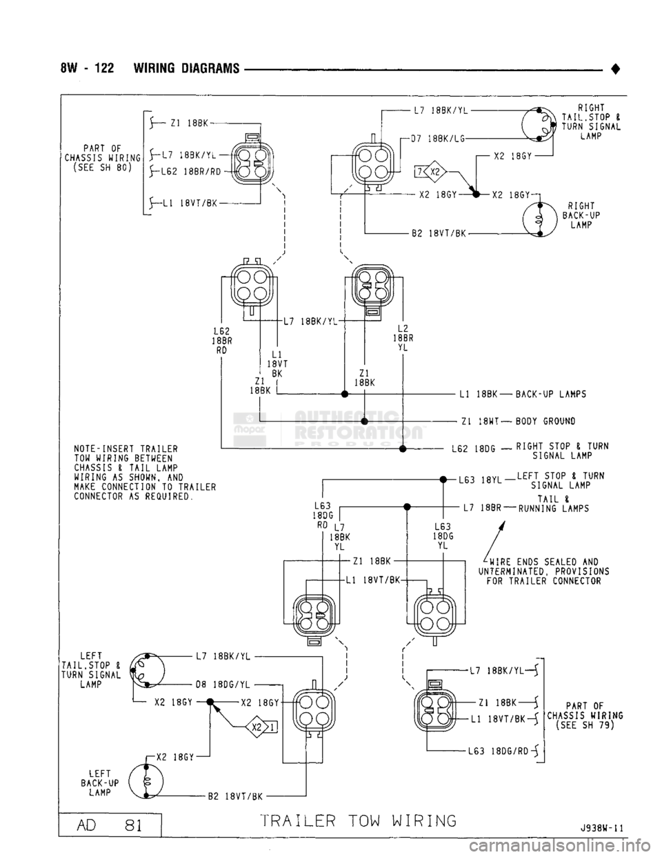
NOTE-INSERT TRAILER TOW WIRING BETWEEN
CHASSIS
I
TAIL
LAMP
WIRING AS SHOWN, AND
MAKE
CONNECTION TO TRAILER
CONNECTOR AS REQUIRED. •L7 18BK/YL-
Zl
18BK LI
18VT BK L2
18BR YL
Zl
18BK LEFT
TAIL,STOP ft
TURN SIGNAL LAMP
LEFT
BACK-UP LAMP - LI 18BK— BACK-UP LAMPS
- Zl
18WT—
BODY GROUND
62 18DG — RIGHT STOP ft TURN SIGNAL LAMP
• r7 1PY. LEFT STOP ft TURN
L63 18YL SIGNAL LAMP L7 18BR-
TAIL
I
•RUNNING LAMPS WIRE
ENDS
SEALED AND
UNTERMINATED, PROVISIONS
FOR
TRAILER CONNECTOR
L7
18BK/YL—5
Zl
18BK—^
LI
18VT/BK-J
L63
18DG/RD-5
PART OF
CHASSIS
WIRING
(SEE
SH 79) B2 18VT/BK
AD 81
TRAILER TOW WIRING
J938W-11
Page 606 of 1502
•
ENGINES ENGINES
9 - 1
CONTENTS
page page
3.9L
ENGINE SERVICE PROCEDURES
17 5.9L
ENGINE SERVICE PROCEDURES
77
5.2L
ENGINE SERVICE PROCEDURES
47
ENGINE DIAGNOSIS
5
5.9L
(DIESEL) ENGINE SERVICE PROCEDURES
. 107
STANDARD SERVICE PROCEDURES
1
STANDARD SERVICE PROCEDURES INDEX
page
Engine
Performance 2
Form-ln-Place
Gaskets
1
Honing
Cylinder
Bores
2
FORM-IN-PLACE GASKETS
There are several places where form-in-place gas
kets are used on the engine. DO NOT use form-in-
place gasket material unless specified. Care must
be taken when applying form-in-place gaskets. Bead
size,
continuity and location are of great importance.
Too thin a bead can result in leakage while too much can result in spill-over. A continuous bead of the
proper width is essential to obtain a leak-free joint. Two types of form-in-place gasket materials are
used in the engine area (Mopar Silicone Rubber Ad
hesive Sealant and Mopar Gasket Maker). Each have different properties and cannot be used interchange ably.
MOPAR SILICONE RUBBER ADHESIWE
SEALANT
Mopar Silicone Rubber Adhesive Sealant, normally
black in color, is available in 3 ounce tubes. Moisture in the air causes the sealant material to cure. This
material is normally used on flexible metal flanges.
It has a shelf life of 1 year and will not properly cure
if over aged. Always inspect the package for the ex
piration date before use.
MOPAR
GASKET MAKER Mopar Gasket Maker, normally red in color, is
available in 6 cc tubes. This anaerobic type gasket
material cures in the absence of air when squeezed
between smooth machined metallic surfaces. It will not cure if left in the uncovered tube. DO NOT use on flexible metal flanges.
page
Hydrostatic
Lock
4
Measuring
with
Plastigage 3
Repair
Damaged
or Worn
Threads
. 4
SURFACE PREPARA
TION
Parts assembled with form-in-place gaskets may be
disassembled without unusual effort. In some in
stances, it may be necessary to lightly tap the part
with a mallet or other suitable tool to break the seal
between the mating surfaces. A flat gasket scraper may also be lightly tapped into the joint but care
must be taken not to damage the mating surfaces.
Scrape or wire brush all gasket surfaces to remove
all loose material. Inspect stamped parts to ensure
gasket rails are flat. Flatten rails with a hammer on a flat plate, if required. Gasket surfaces must be free
of oil and dirt. Make sure the old gasket material is
removed from blind attaching holes.
GASKET
APPLICATION
Assembling parts using a form-in-place gasket re
quires care.
Mopar Silicone Rubber Adhesive Sealant should be
applied in a continuous bead approximately 3 mm (0.12 inch) in diameter. All mounting holes must be
circled. For corner sealing, a 3 or 6 mm (1/8 or 1/4
inch) drop is placed in the center of the gasket con
tact area. Uncured sealant may be removed with a shop towel. Components should be torqued in place
while the sealant is still wet to the touch (within 10
minutes). The use of a locating dowel is recom
mended during assembly to prevent smearing the
material off location.
Mopar Gasket Maker should be applied sparingly
to one gasket surface. The sealant diameter should
be 1.Q0 mm (0.04 inch) or less. Be certain the mate-
Page 607 of 1502
9
- 2
ENGINES
rial surrounds each mounting hole. Excess material
can easily be wiped off. Components should be
torqued in place within 15 minutes. The use of a lo cating dowel is recommended during assembly to pre
vent smearing the material off location.
ENGINE PERFORMANCE
To provide best vehicle performance and lowest ve
hicle emissions, it is most important that the tune-up
be done accurately. Use the specifications listed on
the Vehicle Emission Control Information label found on the engine compartment hood.
(1) Test cranking amperage draw (refer to Group
8B,
Battery/Starter/Generator Service for the proper
procedures).
(2) Tighten the intake manifold bolts (refer to
Group 11, Exhaust System and Intake Manifold for
the proper specifications). (3) Perform cylinder compression test:
(a) Check engine oil level and add oil, if neces
sary.
(b) Drive the vehicle until engine reaches normal
operating temperature. (c) Select a route free from traffic and other
forms of congestion, observe all traffic laws and
briskly accelerate through the gears several times. The higher engine speed may help clean out valve seat deposits which can prevent accurate compres
sion readings.
CAUTION:
DO NOT
overspeed
the
engine.
(d) Remove all spark plugs from engine. As
spark plugs are being removed, check electrodes for
abnormal firing indicators - fouled, hot, oily, etc.
Record cylinder number of spark plug for future
reference.
(e) Disconnect coil wire from distributor and se
cure to good ground to prevent a spark from start
ing a fire.
(f) Be sure throttle blades are fully open during
the compression check. (g) Insert compression gage adaptor into the
No.l spark plug hole. Crank engine until maxi
mum pressure is reached on gauge. Record this
pressure as No.l cylinder pressure.
(h) Repeat Step 3g for all remaining cylinders.
(i) Compression should not be less than 689 kPa
(100 psi) and not vary more than 172 kPa (25 psi)
from cylinder to cylinder.
(j) If cylinder(s) have abnormally low compres
sion pressures, repeat steps 3a through 3h. (k) If the same cylinder(s) repeat an abnormally
low reading, it could indicate the existence of a
problem in the cylinder.
The recommended compression pressures are
to be used only as a guide to diagnosing engine
problems. An engine should NOT be disassem bled to determine the cause of low compression
unless some malfunction is present. (4) Clean or replace spark plugs as necessary. Ad
just gap (refer to Group 8D, Ignition System for gap adjustment and torque).
(5) Test resistance of spark plug cables (refer to
Group 8D, Ignition System.
(6) Inspect the primary wire. Test coil output volt
age,
primary and secondary resistance. Replace parts as necessary (refer to Group 8D, Ignition System and
make necessary adjustment).
(7) Set ignition timing to specifications (refer to
Specification Label on engine compartment hood).
(8) Perform a combustion analysis.
(9) Test fuel pump for pressure and vacuum (refer
to Group 14, Fuel System for the proper specifica
tions).
(10) Inspect air filter element (refer to Group 0,
Lubrication and Maintenance for the proper proce
dure).
(11) Inspect crankcase ventilation system (refer to
Group 0, Lubrication and Maintenance for the proper
procedure).
(12) For emission controls refer to Group 25, Emis
sion Controls System for service procedures.
(13) Inspect and adjust accessory belt drives (refer
to Group 7, Cooling System for the proper adjust
ments).
(14) Road test vehicle as a final test.
H0NIN6
CYLINDER
BORES
Before honing, stuff plenty of clean shop towels un
der the bores and over the crankshaft to keep abra sive materials from entering the crankshaft area.
(1) Used carefully, the Cylinder Bore Sizing Hone
C-823 equipped with 220 grit stones, is the best tool
for this job. In addition to deglazing, it will reduce
taper and out-of-round as well as removing light scuffing, scoring or scratches. Usually a few strokes
will clean up a bore and maintain the required lim
its.
CAUTION:
DO NOT use rigid type
hones
to remove
cylinder
wall
glaze.
(2) Deglazing of the cylinder walls may be done if
the cylinder bore is straight and round. Use a cylin
der surfacing hone, Honing Tool C-3501, equipped
with 280 grit stones (C-3501-3810). 20-60 strokes, de
pending on the bore condition, will be sufficient to
provide a satisfactory surface. Using honing oil C-3501-3880 or a light honing oil available from ma
jor oil distributors.
CAUTION:
DO NOT use engine or
transmission
oil, mineral
spirits
or
kerosene.
Page 609 of 1502
9
- 4 ENGINES
•
RN861
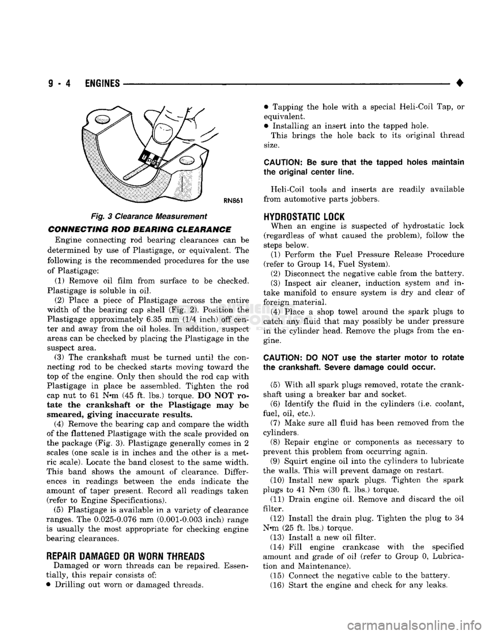
Fig. 3 Clearance Measurement
CONNECTING ROD BEARING CLEARANCE Engine connecting rod bearing clearances can be
determined by use of Plastigage, or equivalent. The
following is the recommended procedures for the use of Plastigage:
(1) Remove oil film from surface to be checked.
Plastigage is soluble in oil.
(2) Place a piece of Plastigage across the entire
width of the bearing cap shell (Fig. 2). Position the
Plastigage approximately 6.35 mm (1/4 inch) off cen
ter and away from the oil holes. In addition, suspect areas can be checked by placing the Plastigage in the
suspect area. (3) The crankshaft must be turned until the con
necting rod to be checked starts moving toward the
top of the engine. Only then should the rod cap with
Plastigage in place be assembled. Tighten the rod
cap nut to 61 Nnn (45 ft. lbs.) torque. DO NOT ro
tate the crankshaft or the Plastigage may be smeared, giving inaccurate results. (4) Remove the bearing cap and compare the width
of the flattened Plastigage with the scale provided on
the package (Fig. 3). Plastigage generally comes in 2 scales (one scale is in inches and the other is a met
ric scale). Locate the band closest to the same width.
This band shows the amount of clearance. Differ ences in readings between the ends indicate the
amount of taper present. Record all readings taken (refer to Engine Specifications). (5) Plastigage is available in a variety of clearance
ranges. The 0.025-0.076 mm (0.001-0.003 inch) range
is usually the most appropriate for checking engine
bearing clearances.
REPAIR DAMAGED OR WORN THREADS Damaged or worn threads can be repaired. Essen
tially, this repair consists of:
• Drilling out worn or damaged threads. • Tapping the hole with a special Heli-Coil Tap, or
equivalent.
• Installing an insert into the tapped hole.
This brings the hole back to its original thread
size.
CAUTION:
Be
sure
that
the tapped holes maintain
the original
center
line.
Heli-Coil tools and inserts are readily available
from automotive parts jobbers.
HYDROSTATIC
LOCK
When an engine is suspected of hydrostatic lock
(regardless of what caused the problem), follow the
steps below. (1) Perform the Fuel Pressure Release Procedure
(refer to Group 14, Fuel System). (2) Disconnect the negative cable from the battery.
(3) Inspect air cleaner, induction system and in
take manifold to ensure system is dry and clear of
foreign material. (4) Place a shop towel around the spark plugs to
catch any fluid that may possibly be under pressure
in the cylinder head. Remove the plugs from the en
gine.
CAUTION:
DO NOT use the starter motor to
rotate
the
crankshaft.
Severe
damage
could
occur.
(5) With all spark plugs removed, rotate the crank
shaft using a breaker bar and socket.
(6) Identify the fluid in the cylinders (i.e. coolant,
fuel, oil, etc.).
(7) Make sure all fluid has been removed from the
cylinders. (8) Repair engine or components as necessary to
prevent this problem from occurring again.
(9) Squirt engine oil into the cylinders to lubricate
the walls. This will prevent damage on restart.
(10) Install new spark plugs. Tighten the spark
plugs to 41 N#m (30 ft. lbs.) torque. (11) Drain engine oil. Remove and discard the oil
filter.
(12) Install the drain plug. Tighten the plug to 34
N-m (25 ft. lbs.) torque.
(13) Install a new oil filter.
(14) Fill engine crankcase with the specified
amount and grade of oil (refer to Group 0, Lubrica
tion and Maintenance). (15) Connect the negative cable to the battery.
(16) Start the engine and check for any leaks.