1993 DODGE TRUCK tow
[x] Cancel search: towPage 633 of 1502

9
- 28 3.9L
ENGINE
•
accompanied by excessive clearance between the
valve stem and rocker arm as valve closes. In either
case,
tappet assembly should be removed for inspec
tion and cleaning.
The valve train generates a noise very much like a
light tappet noise during normal operation. Care
must be taken to ensure that tappets are making the
noise. In general, if more than one tappet seems to
be noisy, its probably not the tappets.
REMOVAL
(1) Remove the air cleaner.
(2) Remove cylinder head cover.
(3) Remove rocker assembly and push rods. Iden
tify push rods to ensure installation in original loca
tion.
(4) Remove intake manifold.
(5) Remove yoke retainer and aligning yokes.
(6) Slide Hydraulic Tappet Remover/Installer Tool
C-4129-A
through opening in cylinder head and seat
tool firmly in the head of tappet.
(7) Pull tappet out of bore with a twisting motion.
If all tappets are to be removed, identify tappets to
ensure installation in original location. (8) If the tappet or bore in cylinder block is scored,
scuffed, or shows signs of sticking, ream the bore to
next oversize. Replace with oversize tappet.
CAUTION:
The
plunger
and
tappet bodies
are not
interchangeable.
The
plunger
and
valve must
al
ways
be fitted to the
original body.
It is
advisable
to
work
on one
tappet
at a
time
to
avoid mixing
of
parts.
Mixed parts
are not
compatible.
DO NOT
dis
assemble
a
tappet
on a
dirty
work bench.
DISASSEMBLE (1) Pry out plunger retainer spring clip (Fig. 17).
(2) Clean varnish deposits from inside of tappet
body above plunger cap.
(3) Invert tappet body and remove plunger cap,
plunger, check valve, check valve spring, check valve retainer and plunger spring (Fig. 17). Check valve
could be flat or ball.
ASSEMBLE (1) Clean all tappet parts in a solvent that will re
move all varnish and carbon.
(2) Replace tappets that are unfit for further ser
vice with new assemblies. (3) If plunger shows signs of scoring or wear, in
stall a new tappet assembly. If valve is pitted, or
valve seat on end of plunger is prevented from seat ing, install a new tappet assembly.
(4) Assemble tappets (Fig. 17).
INSTALLATION
(1) Lubricate tappets.
PLUNGER
SPRING CHECK
BALL PLUNGER
RETAINER
SPRING CLIP
ROLLER
TAPPET
BODY RETAINER
I
PLUNGER
CHECK VALVE
SPRING PLUNGER
CAP
J9109-220
Fig.
17 Hydraulic
Tappet
Assembly
(2) Install tappets and push rods in their original
positions. Ensure that the oil feed hole in the side of
the tappet body faces up (away from the crankshaft).
(3) Install aligning yokes with ARROW toward
camshaft.
(4) Install yoke retainer. Tighten the bolts to 23
N*m (200 in. lbs.) torque. Install intake manifold.
(5) Install push rods in original positions. (6) Install rocker arms.
(7) Install cylinder head cover.
(8) Start and operate engine. Warm up to normal
operating temperature.
CAUTION:
To
prevent damage
to
valve mechanism,
engine must
not be run
above fast idle
until
all hy
draulic tappets have
filled
with
oil and
have become
quiet.
VALVE
TIMING
(1) Turn crankshaft until the No.6 exhaust valve
is closing and No.6 intake valve is opening. (2) Insert a 6.350 mm (1/4 inch) spacer between
rocker arm pad and stem tip of No.l intake valve.
Allow spring load to bleed tappet down giving in ef fect a solid tappet. (3) Install a dial indicator so plunger contacts
valve spring retainer as nearly perpendicular as pos sible. Zero the indicator. (4) Rotate the crankshaft clockwise (normal run
ning direction) until the valve has lifted 0.254 mm (0.010 inch). The timing of the crankshaft should
now read from 10° before top dead center to 2° after
top dead center. Remove spacer.
CAUTION:
DO NOT
turn
crankshaft
any
further
clockwise
as
valve spring might bottom
and
result in serious damage.
(5) If reading is not within specified limits: (a) Check sprocket index marks.
(b) Inspect timing chain for wear. (c) Check accuracy of DC mark on timing indica
tor.
Page 638 of 1502
•
3.9L
ENGINE
9 - 33
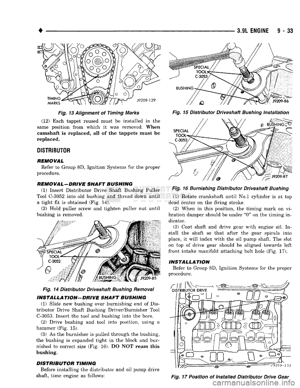
Fig. 13 Alignment of Timing Marks (12) Each tappet reused must be installed in the
same position from which it was removed.
When
camshaft
Is replaced, all of the tappets must be
replaced.
DISTRIBUTOR
REMOVAL
Refer to Group 8D, Ignition Systems for the proper
procedure.
REMOVAL-DRIVE SHAFT BUSHING (1)
Insert Distributor Drive Shaft Bushing Puller
Tool C-3052 into old bushing and thread down until a tight fit is obtained (Fig. 14).
(2)
Hold puller screw and tighten puller nut until
bushing is removed.
Fig.
14 Distributor Driveshaft Bushing Removal
INSTALLATION-DRIVE
SHAFT BUSHING (1) Slide new bushing over burnishing end of Dis
tributor Drive Shaft Bushing Driver/Burnisher Tool
C-3053.
Insert the tool and bushing into the bore. (2) Drive bushing and tool into position, using a
hammer (Fig. 15).
(3) As the burnisher is pulled through the bushing,
the bushing is expanded tight in the block and bur nished to correct size (Fig. 16). DO NOT ream this
bushing.
DISTRIBUTOR
TIMING
Before installing the distributor and oil pump drive
shaft, time engine as follows:
Fig.
16
Burnishing
Distributor Driveshaft
Bushing
(1) Rotate crankshaft until No.l cylinder is at top
dead center on the firing stroke. (2) When in this position, the timing mark on vi
bration damper should be under "0" on the timing in dicator.
(3) Coat shaft and drive gear with engine oil. In
stall the shaft so that after the gear spirals into
place, it will index with the oil pump shaft. The slot on top of drive gear should be aligned towards left
front intake manifold attaching bolt hole (Fig. 17).
INSTALLATION
Refer to Group 8D, Ignition Systems for the proper
procedure.
Fig.
17 Position of Installed Distributor Drive Gear
Page 642 of 1502
(5) Be sure the connecting rod and connecting rod
cap are identified with the cylinder number. Remove
connecting rod cap. Install connecting rod bolt guide
set on connecting rod bolts.
(6) Pistons and connecting rods must be removed
from top of cylinder block. When removing piston and connecting rod assemblies from the engine, ro
tate crankshaft so that the connecting rod is centered in cylinder bore and at BDC. Be careful not to nick
crankshaft journals.
(7) After removal, install bearing cap on the mat
ing rod.
INSPECTION
Check the crankshaft connecting rod journal for ex
cessive wear, taper and scoring. Check the cylinder block bore for out-of-round,
taper, scoring and scuffing.
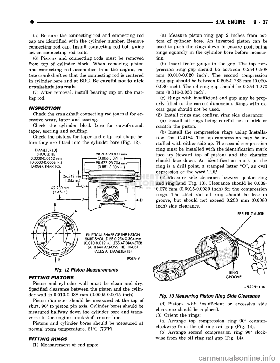
Check the pistons for taper and elliptical shape be
fore they are fitted into the cylinder bore (Fig. 12).
DIAMETER
(D)
SHOULD BE
0.0000-0.0152
mm
(0.0000-0.0006
in.)
LARGER
THAN
(C).
98.704-98.831
mm
-(3.886-3.891
in.)-
98.577-98.704
mm-
(3.881-3.886
in.) (a) Measure piston ring gap 2 inches from bot
tom of cylinder bore. An inverted piston can be used to push the rings down to ensure positioning
rings squarely in the cylinder bore before measur ing.
(b) Insert feeler gauge in the gap. The top com
pression ring gap should be between 0.254-0.508
mm (0.010-0.020 inch). The second compression
ring gap should be between 0.508-0.762 mm (0.020- 0.030 inch). The oil ring gap should be 0.254-1.270
mm (0.010-0.050 inch).
(c) Rings with insufficient end gap may be prop
erly filled to the correct dimension. Rings with ex
cess gaps should not be used.
(2) Install rings and confirm ring side clearance: (a) Install oil rings being careful not to nick or
scratch the piston.
(b) Install the compression rings using Installa
tion Tool C-4184. The top compression may be in stalled with either side up. The second compression
ring must be installed with the identification mark
face up (toward top of piston) and the chamfer should face down. An identification mark on the
ring is a drill point, a stamped letter "O", an oval
depression or the word TOP.
(c) Measure side clearance between piston ring
and ring land (Fig. 13). Clearance should be 0.038-
0.076 mm (0.0015-0.0030 inch) for the compression
rings.
The steel rail oil ring should be free in groove, but should not exceed 0.203 mm (0.0080 inch) side clearance.
FEELER
GAUGE
ELLIPTICAL SHAPE
OF
THE PISTON
SKIRT
SHOULD
BE
0.254-0.304
mm
(0.010-0.012
in.)
LESS
AT DIAMETER
(A)
THAN
ACROSS
THE THRUST
FACES
AT DIAMETER
(B).
J9309-9
Fig.
12
Piston
Measurements
FITTING
PISTONS
Piston and cylinder wall must be clean and dry.
Specified clearance between the piston and the cylin
der wall is 0.013-0.038 mm (0.0005-0.0015 inch). Piston diameter should be measured at the top of
skirt, 90° to piston pin axis. Cylinder bores should be
measured halfway down the cylinder bore and trans
verse to the engine crankshaft center line.
Pistons and cylinder bores should be measured at
normal room temperature, 21°C (70°F).
FITTING
RINGS
(1) Measurement of end gaps: J9209-136
Fig.
13
Measuring
Piston
Ring Side
Clearance (d) Pistons with insufficient or excessive side
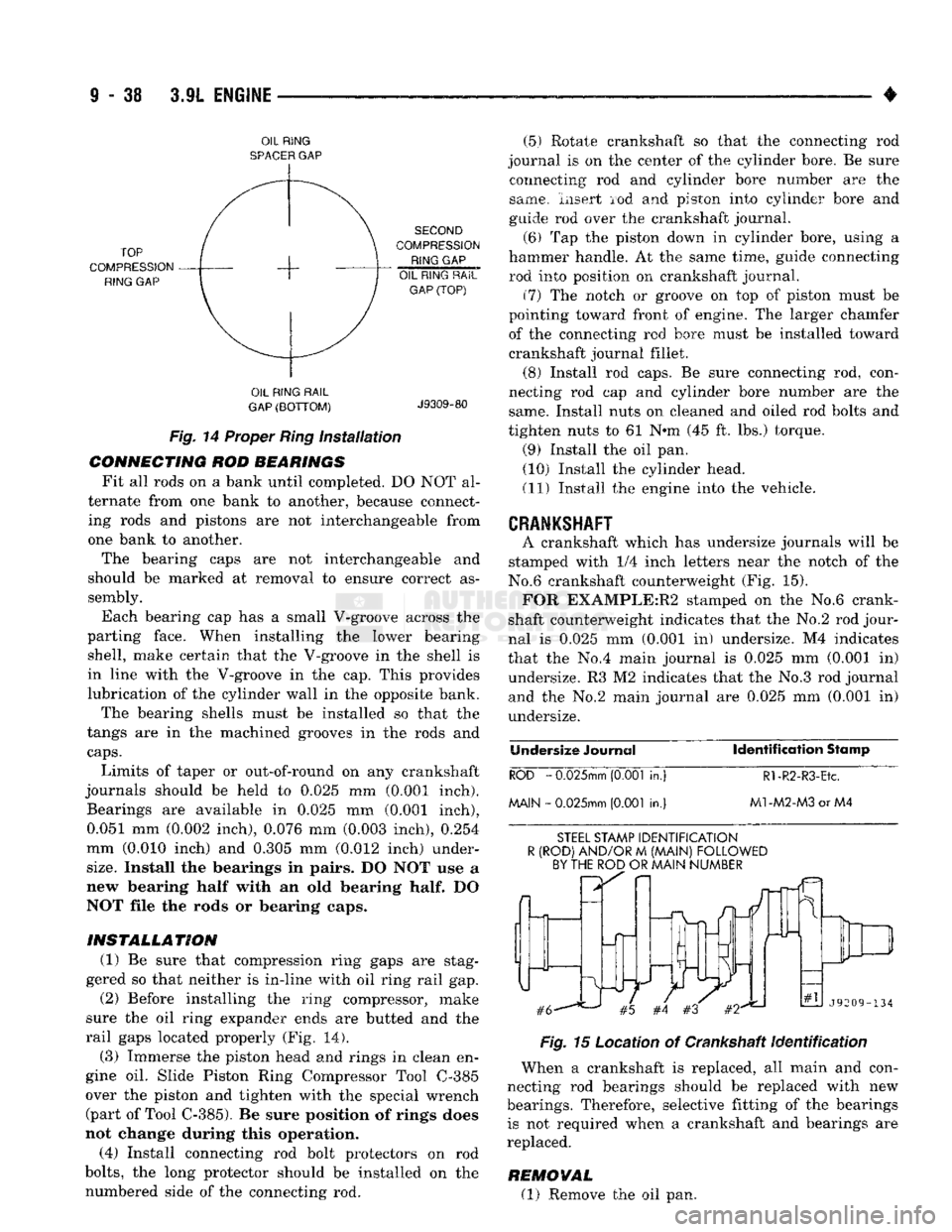
clearance should be replaced. (3) Orient the rings:
(a) Arrange top compression ring 90° counter
clockwise from the oil ring rail gap (Fig. 14). (b) Arrange second compression ring 90° clock
wise from the oil ring rail gap (Fig. 14).
Page 643 of 1502
9
- 38 3.9L
ENGINE
•
OIL
RING
SPACER
GAP
TOP
COMPRESSION
RING
GAP
SECOND
COMPRESSION
RING
GAP
OIL
RING
RAiL
GAP (TOP) OIL
RING
RAIL
GAP
(BOTTOM)
J9309-80
Fig.
14 Proper
Ring
Installation
CONNECTING ROD BEARINGS Fit all rods on a bank until completed. DO NOT al
ternate from one bank to another, because connect ing rods and pistons are not interchangeable from
one bank to another.
The bearing caps are not interchangeable and
should be marked at removal to ensure correct as sembly.
Each bearing cap has a small V-groove across the
parting face. When installing the lower bearing shell, make certain that the V-groove in the shell is
in line with the V-groove in the cap. This provides
lubrication of the cylinder wall in the opposite bank.
The bearing shells must be installed so that the
tangs are in the machined grooves in the rods and
caps.
Limits of taper or out-of-round on any crankshaft
journals should be held to 0.025 mm (0.001 inch). Bearings are available in 0.025 mm (0.001 inch), 0.051 mm (0.002 inch), 0.076 mm (0.003 inch), 0.254
mm (0.010 inch) and 0.305 mm (0.012 inch) under-
size.
Install the bearings in pairs. DO NOT use a
new bearing half with an old bearing
half.
DO
NOT file the rods or bearing caps.
INSTALLATION (1) Be sure that compression ring gaps are stag
gered so that neither is in-line with oil ring rail gap. (2) Before installing the ring compressor, make
sure the oil ring expander ends are butted and the
rail gaps located properly (Fig. 14).
(3) Immerse the piston head and rings in clean en
gine oil. Slide Piston Ring Compressor Tool C-385
over the piston and tighten with the special wrench (part of Tool C-385). Be sure position of rings does
not change during this operation.
(4) Install connecting rod bolt protectors on rod
bolts,
the long protector should be installed on the numbered side of the connecting rod. (5) Rotate crankshaft so that the connecting rod
journal is on the center of the cylinder bore. Be sure connecting rod and cylinder bore number are the
same. Insert rod and piston into cylinder bore and
guide rod over the crankshaft journal.
(6) Tap the piston down in cylinder bore, using a
hammer handle. At the same time, guide connecting
rod into position on crankshaft journal.
(7) The notch or groove on top of piston must be
pointing toward front of engine. The larger chamfer
of the connecting rod bore must be installed toward
crankshaft journal fillet.
(8) Install rod caps. Be sure connecting rod, con
necting rod cap and cylinder bore number are the same. Install nuts on cleaned and oiled rod bolts and
tighten nuts to 61 N»m (45 ft. lbs.) torque.
(9) Install the oil pan. (10) Install the cylinder head.
(11) Install the engine into the vehicle.
CRANKSHAFT
A crankshaft which has undersize journals will be
stamped with 1/4 inch letters near the notch of the
No.6 crankshaft counterweight (Fig. 15). FOR EXAMPLE:R2 stamped on the No.6 crank
shaft counterweight indicates that the No.2 rod jour
nal is 0.025 mm (0.001 in) undersize. M4 indicates
that the No.4 main journal is 0.025 mm (0.001 in) undersize. R3 M2 indicates that the No.3 rod journal
and the No.2 main journal are 0.025 mm (0.001 in) undersize.
Undersize
Journal Identification
Stamp
ROD
-
0.025mm
(0.001
in.)
Rl-R2-R3-Etc.
MAIN -
0.025mm
(0.001
in.)
M1-M2-M3
or M4
STEEL
STAMP
IDENTIFICATION
R
(ROD)
AND/OR
M
(MAIN)
FOLLOWED
BY THE ROD
OR
MAIN
NUMBER
Fig.
15 Location of Crankshaft
Identification
When a crankshaft is replaced, all main and con
necting rod bearings should be replaced with new
bearings. Therefore, selective fitting of the bearings is not required when a crankshaft and bearings are
replaced.
REMOVAL (1) Remove the oil pan.
Page 644 of 1502
•
3.9L
ENGINE
9 - 39 (2) Remove the oil pump from the rear main bear
ing cap.
(8)
Identify bearing caps before removal. Remove
bearing caps and bearings one at a time.
(4) Lift the crankshaft out of the block.
(5) Remove and discard the crankshaft rear oil
seals.
(6)
Remove and discard the front crankshaft oil
seal.
INSPECTION OF JOURNALS The crankshaft connecting rod and main journals
should be checked for excessive wear, taper and scor
ing. The maximum taper or out-of-round on any
crankshaft journal is 0.025 mm (0.001 inch).
Journal grinding should not exceed 0.305 mm
(0.012 inch) under the standard journal diameter. DO
NOT grind thrust faces of No.3 main bearing. DO
NOT nick crank pin or bearing fillets. After grind
ing, remove rough edges from crankshaft oil holes and clean out all oil passages.
CAUTION:
After any journal
grind,
it is important
that
the
final
paper or cloth
polish
be in the
same
direction as the engine rotates.
INSTALLATION (1) Lightly oil the new upper seal lips with engine
oil.
(2) Install the new upper rear bearing oil seal with
the yellow paint facing towards the rear of the en
gine.
(3) Position the crankshaft into the cylinder block.
(4) Lightly oil the new lower seal lips with engine
oil.
(5) Install the new lower rear bearing oil seal into
the bearing cap with the yellow paint facing towards the rear of the engine.
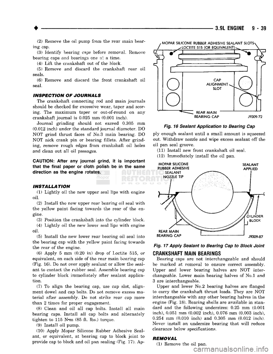
(6) Apply 5 mm (0.20 in) drop of Loctite 515, or
equivalent, on each side of the rear main bearing cap (Fig. 16). Do not over apply sealant or allow the seal
ant to contact the rubber seal. Assemble bearing cap
to cylinder block immediately after sealant applica tion.
(7) To align the bearing cap, use cap slot, align
ment dowel and cap bolts. Do not remove excess ma
terial after assembly. Do not strike rear cap more
than 2 times for proper engagement.
(8) Clean and oil all cap bolts. Install all main
bearing caps. Install all cap bolts and alternately
tighten to 115 N»m (85 ft. lbs.) torque.
(9)
Install oil pump.
(10) Apply Mopar Silicone Rubber Adhesive Seal
ant, or equivalent, at bearing cap to block joint to
provide cap to block and oil pan sealing (Fig. 17). Ap-
BEARING CAP
J9309-72
Fig.
16 Sealant Application to Bearing Cap ply enough sealant until a small amount is squeezed
out. Withdraw nozzle and wipe excess sealant off the
oil pan seal groove.
(11) Install new front crankshaft oil seal. (12) Immediately install the oil pan.
MOPAR SILICONE SEALANT
RUBBER
ADHESIVE APPLIED
Fig.
17
Apply
Sealant to Bearing Cap to
Block
Joint
CRANKSHAFT MAIN BEARINGS
Bearing caps are not interchangeable and should
be marked at removal to ensure correct assembly.
Upper and lower bearing halves are NOT inter changeable. Lower main bearing halves of No.l and
3 are interchangeable. Upper and lower No.2 bearing halves are flanged
to carry the crankshaft thrust loads. They are NOT interchangeable with any other bearing halves in the
engine (Fig. 18). Bearing shells are available in stan
dard and the following undersizes: 0.25 mm (0.001
inch),
0.051 mm (0.002 inch), 0.076 mm (0.003 inch),
0.254 mm (0.010 inch) and 0.305 mm (0.012 inch).
Never install an undersize bearing that will reduce
clearance below specifications.
REMOVAL (1) Remove the oil pan.
Page 645 of 1502
S
- 40 3.9L
ENGINE
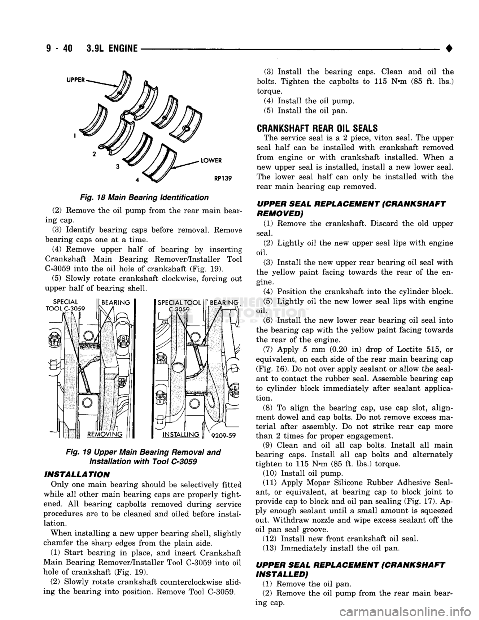
39 Fig.
18 Main Bearing identification
(2) Remove the oil pump from the rear main bear
ing cap.
(3) Identify bearing caps before removal. Remove
bearing caps one at a time.
(4) Remove upper half of bearing by inserting
Crankshaft Main Bearing Remover/Installer Tool
C-3059 into the oil hole of crankshaft (Fig. 19).
(5)
Slowly rotate crankshaft clockwise, forcing out
upper half of bearing shell.
Fig.
19 Upper Main Bearing Removal and installation with Tool
C-3059
INSTALLATION Only one main bearing should be selectively fitted
while all other main bearing caps are properly tight ened. All bearing capbolts removed during service
procedures are to be cleaned and oiled before instal lation.
When installing a new upper bearing shell, slightly
chamfer the sharp edges from the plain side.
(1) Start bearing in place, and insert Crankshaft
Main Bearing Remover/Installer Tool C-3059 into oil
hole of crankshaft (Fig. 19).
(2) Slowly rotate crankshaft counterclockwise slid
ing the bearing into position. Remove Tool C-3059. (3) Install the bearing caps. Clean and oil the
bolts.
Tighten the capbolts to 115 N*m (85 ft. lbs.)
torque.
(4) Install the oil pump. (5) Install the oil pan.
CRANKSHAFT REAR
OIL
SEALS
The service seal is a 2 piece, viton seal. The upper
seal half can be installed with crankshaft removed
from engine or with crankshaft installed. When a
new upper seal is installed, install a new lower seal.
The lower seal half can only be installed with the
rear main bearing cap removed.
UPPER SEAL REPLACEMENT (CRANKSHAFT
REMOVED)
(1) Remove the crankshaft. Discard the old upper
seal.
(2) Lightly oil the new upper seal lips with engine
oil.
(3) Install the new upper rear bearing oil seal with
the yellow paint facing towards the rear of the en
gine.
(4) Position the crankshaft into the cylinder block.
(5) Lightly oil the new lower seal lips with engine
oil.
(6) Install the new lower rear bearing oil seal into
the bearing cap with the yellow paint facing towards the rear of the engine.
(7) Apply 5 mm (0.20 in) drop of Loctite 515, or
equivalent, on each side of the rear main bearing cap (Fig. 16). Do not over apply sealant or allow the seal
ant to contact the rubber seal. Assemble bearing cap
to cylinder block immediately after sealant applica
tion.
(8) To align the bearing cap, use cap slot, align
ment dowel and cap bolts. Do not remove excess ma
terial after assembly. Do not strike rear cap more
than 2 times for proper engagement. (9) Clean and oil all cap bolts. Install all main
bearing caps. Install all cap bolts and alternately
tighten to 115 N*m (85 ft. lbs.) torque. (10) Install oil pump.
(11) Apply Mopar Silicone Rubber Adhesive Seal
ant, or equivalent, at bearing cap to block joint to
provide cap to block and oil pan sealing (Fig. 17). Ap
ply enough sealant until a small amount is squeezed out. Withdraw nozzle and wipe excess sealant off the
oil pan seal groove. (12) Install new front crankshaft oil seal.
(13) Immediately install the oil pan.
UPPER SEAL REPLACEMENT (CRANKSHAFT
INSTALLED)
(1) Remove the oil pan. (2) Remove the oil pump from the rear main bear
ing cap.
Page 646 of 1502
•
3.9L ENGINE
9 - 41 (3) Remove the rear main bearing cap. Remove
and discard the old lower oil seal.
(4) Carefully remove and discard the old upper oil
seal.
(5) Lightly oil the new upper seal lips with engine
oil.
To allow ease of installation of the seal, loosen at
least the 2 main bearing caps forward of the rear
bearing cap.
(6) Rotate the new upper seal into the cylinder
block being careful not to shave or cut the outer sur face of the seal. To assure proper installation, use the installation tool provided with the kit. Install the
new seal with the yellow paint facing towards the
rear of the engine.
(7) Install the new lower rear bearing oil seal into
the bearing cap with the yellow paint facing towards
the rear of the engine.
(8) Apply 5 mm (0.20 in) drop of Loctite 515, or
equivalent, on each side of the rear main bearing cap (Fig. 16). Do not over apply sealant or allow the seal
ant to contact the rubber seal. Assemble bearing cap
to cylinder block immediately after sealant applica
tion. Be sure the yellow paint faces toward the rear of the engine.
(9) To align the bearing cap, use cap slot, align
ment dowel and cap bolts. Do not remove excess ma
terial after assembly. Do not strike rear cap more
than 2 times for proper engagement.
(10) Install the rear main bearing cap with cleaned
and oiled cap bolts. Alternately tighten ALL cap
bolts to 115 N-m (85 ft. lbs.) torque.
(11) Install oil pump.
(12) Apply Mopar Silicone Rubber Adhesive Seal
ant, or equivalent, at bearing cap to block joint to
provide cap to block and oil pan sealing (Fig. 17). Ap
ply enough sealant until a small amount is squeezed out. Withdraw nozzle and wipe excess sealant off the
oil pan seal groove.
(13) Immediately install the oil pan.
LOWER SEAL REPLACEMENT
(1) Remove the oil pan.
(2) Remove the oil pump from the rear main bear
ing cap.
(3) Remove the rear main bearing cap and discard
the old lower seal.
(4) Carefully install a new upper seal (refer to Up
per Seal Replacement - Crankshaft Installed proce dure above).
(5) Lightly oil the new lower seal lips with engine
oil.
(6) Install a new lower seal in bearing cap with
yellow paint facing the rear of engine. (7) Apply 5 mm (0.20 in) drop of Loctite 515, or
equivalent, on each side of the rear main bearing cap (Fig. 16). Do not over apply sealant or allow the seal ant to contact the rubber seal. Assemble bearing cap
to cylinder block immediately after sealant applica tion.
(8) To align the bearing cap, use cap slot, align
ment dowel and cap bolts. Do not remove excess ma
terial after assembly. Do not strike rear cap more
than 2 times for proper engagement.
(9) Install the rear main bearing cap with cleaned
and oiled cap bolts. Alternately tighten the cap bolts
to 115 Nnn (85 ft. lbs.) torque.
(10) Install oil pump.
(11) Apply Mopar Silicone Rubber Adhesive Seal
ant, or equivalent, at bearing cap to block joint to
provide cap to block and oil pan sealing (Fig. 17). Ap
ply enough sealant until a small amount is squeezed out. Withdraw nozzle and wipe excess sealant off the
oil pan seal groove.
(12) Immediately install the oil pan.
CYLINDER
BLOCK
Remove the engine assembly from the vehicle.
DISASSEMBLE
(1) Remove the cylinder head. (2) Remove the oil pan.
(3) Remove the piston/connecting rod assembly.
CLEANING
Clean cylinder block thoroughly and check all core
hole plugs for evidence of leaking.
INSPECTION
Examine block for cracks or fractures.
The cylinder walls should be checked for
out-of-
round and taper with Cylinder Bore Indicator Tool C-119. The cylinder block should be bored and honed
with new pistons and rings fitted if:
• The cylinder bores show more than 0.127 mm (0.005 inch) out-of-round.
• The cylinder bores show a taper of more than 0.254 mm (0.010 inch).
• The cylinder walls are badly scuffed or scored. Boring and honing operation should be closely co
ordinated with the fitting of pistons and rings so specified clearances may be maintained.
Refer to Standard Service Procedures in the begin
ning of this Group for the proper honing of cylinder
bores.
OIL LINE PLUG
The oil line plug is located in the vertical passage
at the rear of the block between the Oil-To-Filter and
Oil-From-Filter passages (Fig. 20). Improper installa
tion or plug missing could cause erratic, low or no oil pressure.
(1) Remove oil pressure sending unit from back of
block.
Page 663 of 1502
CAUTION:
Th© plunger and
tappet
bodies are not
interchangeable. The plunger and valve must al
ways
be
fitted
to the
original
body. It is advisable to
work
on one
tappet
at a
time
to avoid
mixing
of parts. Mixed
parts
are not
compatible.
DO NOT
dis
assemble
a
tappet
on a
dirty
work
bench,
DISASSEMBLE
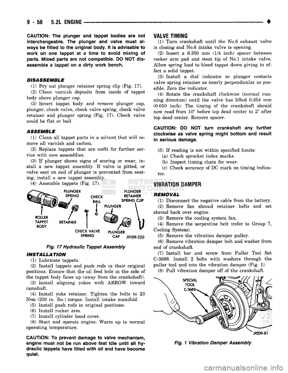
(1) Pry out plunger retainer spring clip (Fig. 17).
(2) Clean varnish deposits from inside of tappet
body above plunger cap.
(3) Invert tappet body and remove plunger cap,
plunger, check valve, check valve spring, check valve
retainer and plunger spring (Fig. 17). Check valve could be flat or ball.
ASSEMBLE
(1) Clean all tappet parts in a solvent that will re
move all varnish and carbon.
(2) Replace tappets that are unfit for further ser
vice with new assemblies.
(3) If plunger shows signs of scoring or wear, in
stall a new tappet assembly. If valve is pitted, or
valve seat on end of plunger is prevented from seat
ing, install a new tappet assembly. (4) Assemble tappets (Fig. 17).
PLUNGER
CHECK
BALL
PLUNGER
RETAINER
SPRING CLIP
ROLLER
TAPPET BODY RETAINER I PLUNGER
CHECK VALVE
SPRING PLUNGER
CAP
J9109-220
Fig.
17 Hydraulic
Tappet
Assembly
INSTALLATION
(1) Lubricate tappets.
(2) Install tappets and push rods in their original
positions. Ensure that the oil feed hole in the side of
the tappet body faces up (away from the crankshaft). (3) Install aligning yokes with ARROW toward
camshaft. (4) Install yoke retainer. Tighten the bolts to 23
N»m (200 in. lbs.) torque. Install intake manifold. (5) Install push rods in original positions.
(6) Install rocker arm.
(7) Install cylinder head cover.
(8) Start and operate engine. Warm up to normal
operating temperature.
CAUTION: To
prevent
damage to valve mechanism,
engine must not be run above
fast
idle
until
all hy
draulic
tappets
have
filled
with
oil and have become
quiet.
VALVE
TIMING
(1) Turn crankshaft until the No.6 exhaust valve
is closing and No.6 intake valve is opening. (2) Insert a 6.350 mm (1/4 inch) spacer between
rocker arm pad and stem tip of No.l intake valve. Allow spring load to bleed tappet down giving in ef
fect a solid tappet. (3) Install a dial indicator so plunger contacts
valve spring retainer as nearly perpendicular as pos
sible.
Zero the indicator. (4) Rotate the crankshaft clockwise (normal run
ning direction) until the valve has lifted 0.254 mm (0.010 inch). The timing of the crankshaft should
now read from 10° before top dead center to 2° after
top dead center. Remove spacer.
CAUTION:
DO NOT
turn
crankshaft any
further
clockwise as valve spring
might
bottom
and
result
in serious
damage.
(5) If reading is not within specified limits: (a) Check sprocket index marks.
(b) Inspect timing chain for wear.
(c) Check accuracy of DC mark on timing indica
tor.
VIBRATION DAMPER
REMOVAL (1) Disconnect the negative cable from the battery.
(2) Remove fan shroud retainer bolts and set
shroud back over engine.
(3) Remove the cooling system fan.
(4) Remove the serpentine belt (refer to Group 7,
Cooling System).
(5) Remove the vibration damper pulley. (6) Remove vibration damper bolt and washer from
end of crankshaft. (7) Install bar and screw from Puller Tool Set
C-3688. Install 2 bolts with washers through the
puller tool and into the vibration damper (Fig. 1).
(8) Pull vibration damper off of the crankshaft.
J9209-81
Fig.
1
Vibration
Damper
Assembly