1993 DODGE TRUCK tow
[x] Cancel search: towPage 668 of 1502
•
5.2L
ENGINE
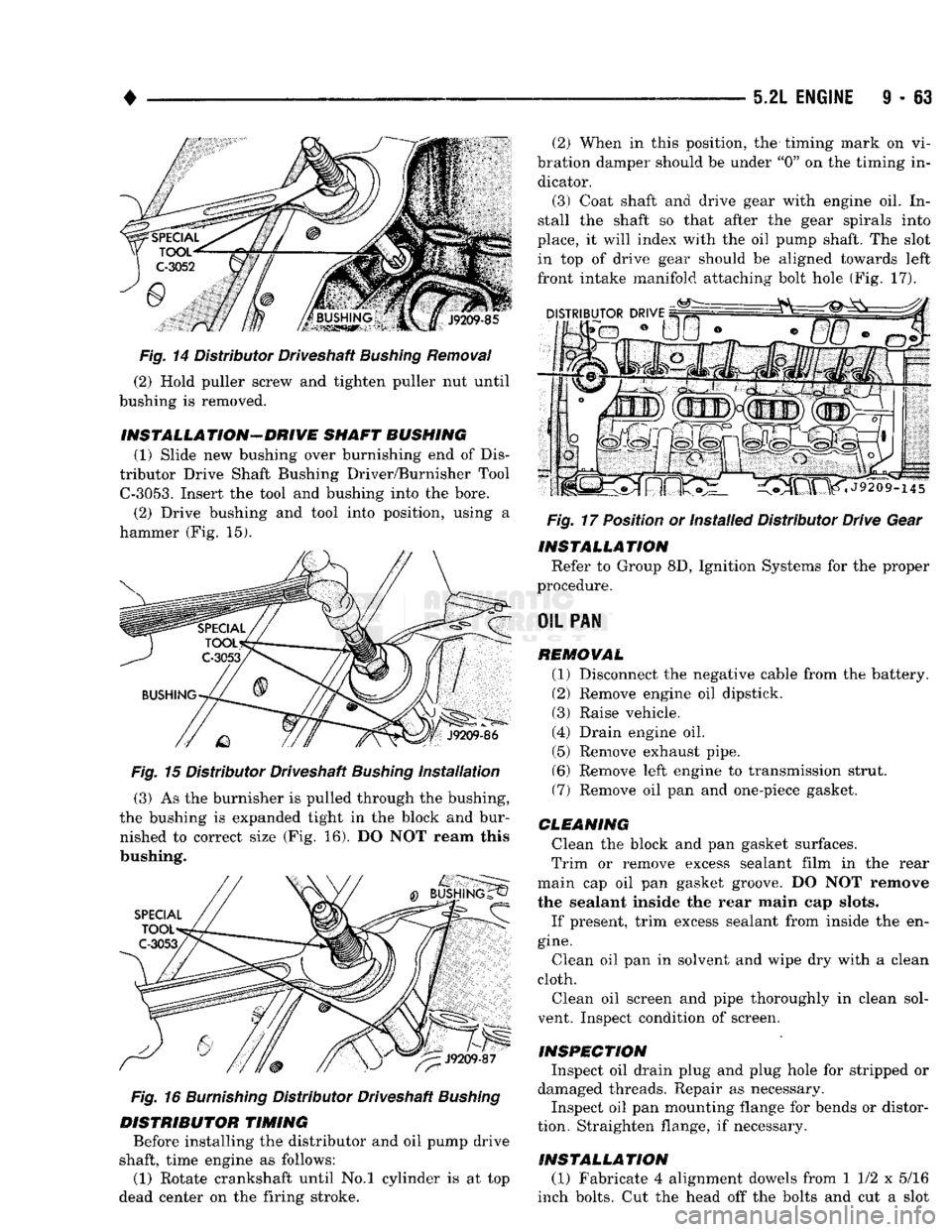
I - 63
Fig.
14 Distributor Driveshaft
Bushing
Removal
(2) Hold puller screw and tighten puller nut until
bushing is removed.
INSTALLA TION-DRIVE
SHAFT BUSHING
(1) Slide new bushing over burnishing end of Dis
tributor Drive Shaft Bushing Driver/Burnisher Tool
C-3053.
Insert the tool and bushing into the bore. (2) Drive bushing and tool into position, using a
hammer (Fig. 15).
Fig. 15 Distributor Driveshaft Bushing Installation (3) As the burnisher is pulled through the bushing,
the bushing is expanded tight in the block and bur nished to correct size (Fig. 16). DO NOT ream this
bushing.
Fig.
16
Burnishing
Distributor Driveshaft
Bushing
DISTRIBUTOR TIMING Before installing the distributor and oil pump drive
shaft, time engine as follows:
(1) Rotate crankshaft until No.l cylinder is at top
dead center on the firing stroke. (2) When in this position, the timing mark on vi
bration damper should be under "0" on the timing in dicator.
(3) Coat shaft and drive gear with engine oil. In
stall the shaft so that after the gear spirals into
place, it will index with the oil pump shaft. The slot in top of drive gear should be aligned towards left
front intake manifold attaching bolt hole (Fig. 17).
Fig.
17 Position or Installed Distributor Drive Gear
INSTALLATION Refer to Group 8D, Ignition Systems for the proper
procedure.
OIL
PAN REMOVAL (1) Disconnect the negative cable from the battery.
(2) Remove engine oil dipstick. (3) Raise vehicle.
(4) Drain engine oil. (5) Remove exhaust pipe.
(6) Remove left engine to transmission strut.
(7) Remove oil pan and one-piece gasket.
CLEANING Clean the block and pan gasket surfaces.
Trim or remove excess sealant film in the rear
main cap oil pan gasket groove. DO NOT remove
the sealant inside the rear main cap slots.
If present, trim excess sealant from inside the en
gine.
Clean oil pan in solvent and wipe dry with a clean
cloth.
Clean oil screen and pipe thoroughly in clean sol
vent. Inspect condition of screen.
INSPECTION Inspect oil drain plug and plug hole for stripped or
damaged threads. Repair as necessary.
Inspect oil pan mounting flange for bends or distor
tion. Straighten flange, if necessary.
INSTALLATION (1) Fabricate 4 alignment dowels from 1 1/2 x 5/16
inch bolts. Cut the head off the bolts and cut a slot
Page 672 of 1502
•
5.2L
ENGINE
I - 67
DIAMETER
(D)
SHOULD
BE
0.0000-0.0152
mm
(0.0000-0.0006
in.)
LARGER
THAN
(C).
98.704-98.831
mm
•
(3.886-3.891
in.)-
FEELER
GAUGE
62.230
mm (2.45 in.)
1
26.543
mm
(1.045
in.)
±c
ELLIPTICAL
SHAPE
OF
THE
PISTON
SKIRT
SHOULD
BE
0.254-0.304
mm
(0.010-0.012
in.)
LESS AT
DIAMETER
(A)
THAN
ACROSS
THE
THRUST
FACES
AT
DIAMETER
(B).
J9309-9
Fig.
12
Piston
Measurements
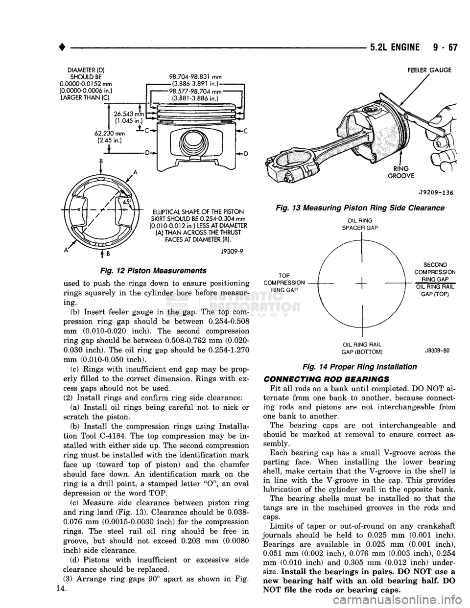
used to push the rings down to ensure positioning
rings squarely in the cylinder bore before measur ing.
(b) Insert feeler gauge in the gap. The top com
pression ring gap should be between 0.254-0.508 mm (0.010-0.020 inch). The second compression
ring gap should be between 0.508-0.762 mm (0.020-0.030 inch). The oil ring gap should be 0.254-1.270
mm (0.010-0.050 inch).
(c) Rings with insufficient end gap may be prop
erly filled to the correct dimension. Rings with ex cess gaps should not be used.
(2) Install rings and confirm ring side clearance: (a) Install oil rings being careful not to nick or
scratch the piston.
(b) Install the compression rings using Installa
tion Tool C-4184. The top compression may be in stalled with either side up. The second compression
ring must be installed with the identification mark
face up (toward top of piston) and the chamfer should face down. An identification mark on the
ring is a drill point, a stamped letter "O", an oval
depression or the word TOP.
(c) Measure side clearance between piston ring
and ring land (Fig. 13). Clearance should be 0.038-
0.076 mm (0.0015-0.0030 inch) for the compression
rings.
The steel rail oil ring should be free in
groove, but should not exceed 0.203 mm (0.0080
inch) side clearance.
(d) Pistons with insufficient or excessive side
clearance should be replaced. (3) Arrange ring gaps 90° apart as shown in Fig.
RING
GROOVE
J9209-136
Fig.
13
Measuring
Piston
Ring
Side
Clearance
OIL
RING
SPACER
GAP
TOP
COMPRESSION
RING
GAP
SECOND
COMPRESSION
RING
GAP
OIL
RING
RAIL
GAP (TOP) OIL
RING
RAIL
GAP
(BOTTOM)
J9309-80
14. Fig.
14 Proper
Ring
Installation
CONNECTING
ROD
BEARINGS
Fit all rods on a bank until completed. DO NOT al
ternate from one bank to another, because connect ing rods and pistons are not interchangeable from
one bank to another.
The bearing caps are not interchangeable and
should be marked at removal to ensure correct as
sembly.
Each bearing cap has a small V-groove across the
parting face. When installing the lower bearing shell, make certain that the V-groove in the shell is
in line with the V-groove in the cap. This provides
lubrication of the cylinder wall in the opposite bank.
The bearing shells must be installed so that the
tangs are in the machined grooves in the rods and
caps.
Limits of taper or out-of-round on any crankshaft
journals should be held to 0.025 mm (0.001 inch). Bearings are available in 0.025 mm (0.001 inch), 0.051 mm (0.002 inch), 0.076 mm (0.003 inch), 0.254
mm (0.010 inch) and 0.305 mm (0.012 inch) under
size.
Install the bearings in pairs. DO NOT use a
new bearing half with an old bearing
half.
DO
NOT file the rods or bearing caps.
Page 673 of 1502
9
- 68 5.2L
ENGINE
• INSTALLATION
(1) Be sure that compression ring gaps are stag
gered so that neither is in-line with oil ring rail gap.
(2) Before installing the ring compressor, make
sure the oil ring expander ends are butted and the
rail gaps located properly (Fig. 14).
(3) Immerse the piston head and rings in clean en
gine oil. Slide Piston Ring Compressor Tool C-385
over the piston and tighten with the special wrench (part of Tool C-385). Be sure position of rings does
not change during this operation.
(4) Install connecting rod bolt protectors on rod
bolts,
the long protector should be installed on the numbered side of the connecting rod. (5) Rotate crankshaft so that the connecting rod
journal is on the center of the cylinder bore. Be sure connecting rod and cylinder bore number are the same. Insert rod and piston into cylinder bore and
guide rod over the crankshaft journal.
(6) Tap the piston down in cylinder bore, using a
hammer handle. At the same time, guide connecting rod into position on crankshaft journal.
(7) The notch or groove on top of piston must be
pointing toward front of engine. The larger chamfer
of the connecting rod bore must be installed toward
crankshaft journal fillet.
(8) Install rod caps. Be sure connecting rod, con
necting rod cap and cylinder bore number are the same. Install nuts on cleaned and oiled rod bolts and
tighten nuts to 61 N®m (45 ft. lbs.) torque.
(9) Install the oil pan.
(10) Install the cylinder head.
(11) Install the engine into the vehicle.
CRANKSHAFT
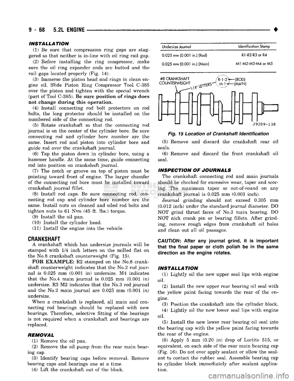
A crankshaft which has undersize journals will be
stamped with 1/4 inch letters on the milled flat on
the No.8 crankshaft counterweight (Fig. 15).
FOR
EXAMPLE: R2 stamped on the No.8 crank
shaft counterweight indicates that the No.2 rod jour
nal is 0.025 mm (0.001 in) undersize. M4 indicates
that the No.4 main journal is 0.025 mm (0.001 in) undersize. R3 M2 indicates that the No.3 rod journal and the No.2 main journal are 0.025 mm (0.Q01 in)
undersize. When a crankshaft is replaced, all main and con
necting rod bearings should be replaced with new
bearings. Therefore, selective fitting of the bearings is not required when a crankshaft and bearings are
replaced.
REMOVAL (1) Remove the oil pan.
(2) Remove the oil pump from the rear main bear
ing cap. (3) Identify bearing caps before removal. Remove
bearing caps and bearings one at a time. (4) Lift the crankshaft out of the block.
Undersize
Journal
Identification
Stamp
0.025
mm
(0.001
in.)
(Rod)
R1-R2-R3
or R4
0.025
mm
(0.001
in.) (Main)
M1-M2-M3-M4
or M5
#8
CRANKSHAFT
COUNTERWEIGHT
(ROD)
(MAIN)
f
J9209-138
Fig.
15 Location of Crankshaft
Identification
(5) Remove and discard the crankshaft rear oil
seals.
(6) Remove and discard the front crankshaft oil
seal.
INSPECTION OF JOURNALS The crankshaft connecting rod and main journals
should be checked for excessive wear, taper and scor
ing. The maximum taper or out-of-round on any crankshaft journal is 0.025 mm (0.001 inch). Journal grinding should not exceed 0.305 mm
(0.012 inch) under the standard journal diameter. DO
NOT grind thrust faces of No.3 main bearing. DO
NOT nick crank pin or bearing fillets. After grind ing, remove rough edges from crankshaft oil holes
and clean out all oil passages.
CAUTION:
After any journal
grind,
it is important
that
the
final
paper or cloth
polish
be in the
same
direction as the engine rotates.
INSTALLATION (1) Lightly oil the new upper seal lips with engine
oil.
(2) Install the new upper rear bearing oil seal with
the yellow paint facing towards the rear of the en
gine.
(3) Position the crankshaft into the cylinder block.
(4) Lightly oil the new lower seal lips with engine
oil.
(5) Install the new lower rear bearing oil seal into
the bearing cap with the yellow paint facing towards
the rear of the engine.
(6)
Apply 5 mm (0.20 in) drop of Loctite 515, or
equivalent, on each side of the rear main bearing cap (Fig. 16). Do not over apply sealant or allow the seal
ant to contact the rubber seal. Assemble bearing cap
to cylinder block immediately after sealant applica tion.
Page 675 of 1502
INSTALLATION
Only one main bearing should be selectively fitted
while all other main bearing caps are properly tight ened. All bearing capbolts removed during service
procedures are to be cleaned and oiled before instal lation. When installing a new upper bearing shell, slightly
chamfer the sharp edges from the plain side.
(1) Start bearing in place, and insert Crankshaft
Main Bearing Remover/Installer Tool C-3059 into oil
hole of crankshaft (Fig. 19).
(2) Slowly rotate crankshaft counterclockwise slid
ing the bearing into position. Remove Tool C-3059.
(3) Install the bearing cap. Clean and oil the bolts.
Tighten the capbolts to 115 N»m (85 ft. lbs.) torque.
(4) Install the oil pump.
(5) Install the oil pan.
CRANKSHAFT REAR
OIL
SEALS
The service seal is a 2 piece, viton seal. The upper
seal half can be installed with crankshaft removed
from engine or with crankshaft installed. When a
new upper seal is installed, install a new lower seal.
The lower seal half can only be installed with the rear main bearing cap removed.
UPPER SEAL REPLACEMENT (CRANKSHAFT
REMOVED) (1) Remove the crankshaft. (2) Lightly oil the new upper seal lips with engine
oil.
(3) Install the new upper rear bearing oil seal with
the yellow paint facing towards the rear of the en
gine.
(4) Position the crankshaft into the cylinder block.
(5) Lightly oil the new lower seal lips with engine
oil.
(6) Install the new lower rear bearing oil seal into
the bearing cap with the yellow paint facing towards the rear of the engine. (7) Apply 5 mm (0.20 in) drop of Loctite 515, or
equivalent, on each side of the rear main bearing cap (Fig. 16). Do not over apply sealant or allow the seal
ant to contact the rubber seal. Assemble bearing cap
to cylinder block immediately after sealant applica
tion.
(8) To align the bearing cap, use cap slot, align
ment dowel and cap bolts. Do not remove excess ma
terial after assembly. Do not strike rear cap more
than 2 times for proper engagement.
(9) Clean and oil all cap bolts. Install all main
bearing caps. Install all cap bolts and alternately tighten to 115 N*m (85 ft. lbs.) torque. (10) Install oil pump.
(11) Apply Mopar Silicone Rubber Adhesive Seal
ant, or equivalent, at bearing cap to block joint to
provide cap to block and oil pan sealing (Fig. 17). Ap ply enough sealant until a small amount is squeezed
out. Withdraw nozzle and wipe excess sealant off the
oil pan seal groove. (12) Install new front crankshaft oil seal.
(13) Immediately install the oil pan.
UPPER SEAL
REPLACEMENT (CRANKSHAFT
INSTALLED)
(1) Remove the oil pan.
(2) Remove the oil pump from the rear main bear
ing cap.
(3) Remove the rear main bearing cap. Remove
and discard the old lower oil seal.
(4)
Carefully remove and discard the old upper oil
seal.
(5)
Lightly oil the new upper seal lips with engine
oil.
To allow ease of installation of the seal, loosen at
least the 2 main bearing caps forward of the rear
bearing cap.
(6) Rotate the new upper seal into the cylinder
block being careful not to shave or cut the outer sur face of the seal. To assure proper installation, use the installation tool provided with the kit. Install the
new seal with the yellow paint facing towards the
rear of the engine.
(7) Install the new lower rear bearing oil seal into
the bearing cap with the yellow paint facing towards
the rear of the engine.
(8) Apply 5 mm (0.20 in) drop of Loctite 515, or
equivalent, on each side of the rear main bearing cap (Fig. 16). Do not over apply sealant or allow the seal
ant to contact the rubber seal. Assemble bearing cap
to cylinder block immediately after sealant applica
tion. Be sure the yellow paint faces toward the rear of the engine. (9) To align the bearing cap, use cap slot, align
ment dowel and cap bolts. Do not remove excess ma
terial after assembly. Do not strike rear cap more than 2 times for proper engagement. (10) Install the rear main bearing cap with cleaned
and oiled cap bolts. Alternately tighten ALL cap
bolts to 115 N*m (85 ft. lbs.) torque. (11) Install oil pump.
(12) Apply Mopar Silicone Rubber Adhesive Seal
ant, or equivalent, at bearing cap to block joint to
provide cap to block and oil pan sealing (Fig. 17). Ap
ply enough sealant until a small amount is squeezed out. Withdraw nozzle and wipe excess sealant off the
oil pan seal groove. (13) Immediately install the oil pan.
LOWER SEAL REPLACEMENT (1) Remove the oil pan.
(2)
Remove the oil pump from the rear main bear
ing cap. (3) Remove the rear main bearing cap and discard
the old lower seal.
Page 698 of 1502
•
5.9L
ENGINE
9 - 93
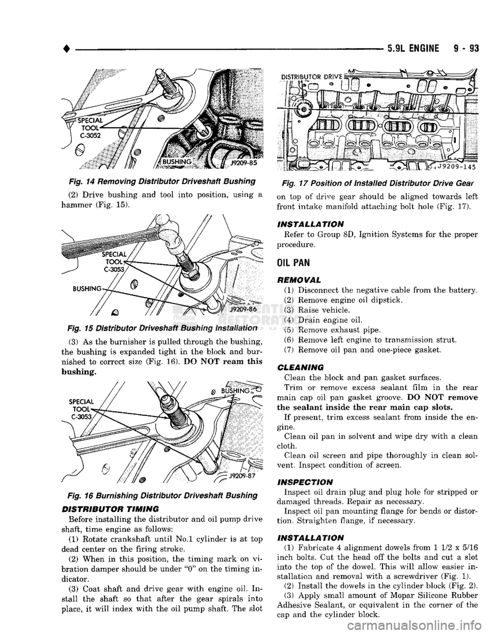
Fig.
14
Removing
Distributor Driveshaft
Bushing
(2) Drive bushing and tool into position, using a
hammer (Fig. 15).
Fig.
15 Distributor Driveshaft
Bushing
Installation
(3) As the burnisher is pulled through the bushing,
the bushing is expanded tight in the block and bur nished to correct size (Fig. 16). DO NOT ream this
bushing.
Fig.
16
Burnishing
Distributor Driveshaft
Bushing
DISTRIBUTOR
TIMING
Before installing the distributor and oil pump drive
shaft, time engine as follows: (1) Rotate crankshaft until No.l cylinder is at top
dead center on the firing stroke. (2) When in this position, the timing mark on vi
bration damper should be under "0" on the timing in dicator.
(3) Coat shaft and drive gear with engine oil. In
stall the shaft so that after the gear spirals into
place, it will index with the oil pump shaft. The slot
Fig.
17 Position of Installed Distributor Drive Gear
on top of drive gear should be aligned towards left
front intake manifold attaching bolt hole (Fig. 17).
INSTALLATION
Refer to Group 8D, Ignition Systems for the proper
procedure.
OIL
PAN
REMOVAL
(1) Disconnect the negative cable from the battery.
(2) Remove engine oil dipstick.
(3) Raise vehicle.
(4) Drain engine oil. (5) Remove exhaust pipe.
(6) Remove left engine to transmission strut.
(7) Remove oil pan and one-piece gasket.
CLEANING
Clean the block and pan gasket surfaces.
Trim or remove excess sealant film in the rear
main cap oil pan gasket groove. DO NOT remove
the sealant inside the rear main cap slots.
If present, trim excess sealant from inside the en
gine.
Clean oil pan in solvent and wipe dry with a clean
cloth. Clean oil screen and pipe thoroughly in clean sol
vent. Inspect condition of screen.
INSPECTION
Inspect oil drain plug and plug hole for stripped or
damaged threads. Repair as necessary.
Inspect oil pan mounting flange for bends or distor
tion. Straighten flange, if necessary.
INSTALLATION
(1) Fabricate 4 alignment dowels from 1 1/2 x 5/16
inch bolts. Cut the head off the bolts and cut a slot into the top of the dowel. This will allow easier installation and removal with a screwdriver (Fig. 1).
(2) Install the dowels in the cylinder block (Fig. 2). (3) Apply small amount of Mopar Silicone Rubber
Adhesive Sealant, or equivalent in the corner of the cap and the cylinder block.
Page 702 of 1502
![DODGE TRUCK 1993 Service Repair Manual
•
5.9L
ENGINE
9 - 97
DIAMETER
(D)
SHOULD
BE
0.0000-0.0152
mm
(0.0000-0.0006
in.
LARGER
THAN
(C)
98.704-98.831
mm
(3.886-3.891
in.]
FEELER
GAUGE
H-c -#-D
ELLIPTICAL](/manual-img/12/56922/w960_56922-701.png "DODGE TRUCK 1993 Service Repair Manual
•
5.9L
ENGINE
9 - 97
DIAMETER
(D)
SHOULD
BE
0.0000-0.0152
mm
(0.0000-0.0006
in.
LARGER
THAN
(C)
98.704-98.831
mm
(3.886-3.891
in.]
FEELER
GAUGE
H-c -#-D
ELLIPTICAL")
•
5.9L
ENGINE
9 - 97
DIAMETER
(D)
SHOULD
BE
0.0000-0.0152
mm
(0.0000-0.0006
in.
LARGER
THAN
(C)
98.704-98.831
mm
(3.886-3.891
in.]
FEELER
GAUGE
H-c -#-D
ELLIPTICAL
SHAPE
OF
THE
PISTON
SKIRT
SHOULD
BE
0.254-0.304
mm
(0.010-0.012
in.)
LESS AT
DIAMETER
(A)
THAN
ACROSS
THE
THRUST
FACES
AT
DIAMETER
(B).
J9309-9
Fig.
12
Piston
Measurements (0.010-0.020 inch). The second compression ring
gap should be between 0.508-0.762 mm (0.020-
0.030 inch). The oil ring gap should be 0.254-1.270
mm (0.010-0.050 inch).
(c) Rings with insufficient end gap may be prop
erly filled to the correct dimension. Rings with ex
cess gaps should not be used.
(2) Install rings and confirm ring side clearance: (a) Install oil rings being careful not to nick or
scratch the piston.
(b) Install the compression rings using Installa
tion Tool C-4184. The top compression may be in stalled with either side up. The second compression
ring must be installed with the identification mark
face up (toward top of piston) and the chamfer should face down. An identification mark on the
ring is a drill point, a stamped letter "O", an oval depression or the word TOP.
(c) Measure side clearance between piston ring
and ring land (Fig. 13). Clearance should be 0.038-
0.076 mm (0.0015-0.0030 inch) for the compression
rings.
The steel rail oil ring should be free in groove, but should not exceed 0.203 mm (0.0080
inch) side clearance. (d) Pistons with insufficient or excessive side
clearance should be replaced. (3) Arrange ring gaps 90° apart as shown in Fig.
14.
CONNECTING ROD BEARINGS Fit all rods on a bank until completed. DO NOT al
ternate from one bank to another, because connect ing rods and pistons are not interchangeable from
one bank to another.
GROOVE
J9209-136
Fig.
13
Measuring
Piston
Ring
Side
Clearance
OIL
RING
SPACER
GAP
TOP
COMPRESSION
RING
GAP
SECOND
COMPRESSION
RING
GAP
OIL
RING
RAIL
GAP (TOP) OIL
RING
RAIL
GAP
(BOTTOM)
J9309-80
Fig.
14 Proper
Ring
Installation
The bearing caps are not interchangeable and
should be marked at removal to ensure correct as sembly.
Each bearing cap has a small V-groove across the
parting face. When installing the lower bearing
shell, make certain that the V-groove in the shell is
in line with the V-groove in the cap. This provides
lubrication of the cylinder wall in the opposite bank.
The bearing shells must be installed so that the
tangs are in the machined grooves in the rods and
caps.
Limits of taper or out-of-round on any crankshaft
journals should be held to 0.025 mm (0.001 inch). Bearings are available in 0.025 mm (0.001 inch), 0.051 mm (0.002 inch), 0.076 mm (0.003 inch), 0.254
mm (0.010 inch) and 0.305 mm (0.012 inch) under
size.
Install the bearings in pairs. DO NOT use a
new bearing half with an old bearing
half.
DO
NOT file the rods or bearing caps.
INSTALLATION (1) Be sure that compression ring gaps are stag
gered so that neither is in line with oil ring rail gap.
Page 703 of 1502
(2) Before installing the ring compressor, make
sure the oil ring expander ends are butted and the
rail gaps located properly (Fig. 14).
(3) Immerse the piston head and rings in clean en
gine oil. Slide Piston Ring Compressor Tool C-385
over the piston and tighten with the special wrench (part of Tool C-385). Be
sure position
of
rings does
not change
during this operation.
(4) Install connecting rod bolt protectors on rod
bolts,
the long protector should be installed on the numbered side of the connecting rod. (5) Rotate crankshaft so that the connecting rod
journal is on the center of the cylinder bore. Be sure connecting rod and cylinder bore number are the same. Insert rod and piston into cylinder bore and
guide rod over the crankshaft journal.
(6) Tap the piston down in cylinder bore, using a
hammer handle. At the same time, guide connecting
rod into position on crankshaft journal. (7) The notch or groove on top of piston must be
pointing toward front of engine. The larger chamfer of the connecting rod bore must be Installed toward
crankshaft journal fillet.
(8) Install rod caps. Install nuts on cleaned and
oiled rod bolts and tighten nuts to 61 N*m (45 ft. lbs.)
torque. (9) Install the oil pan.
(10) Install the cylinder head.
(11) Install the engine Into the vehicle.
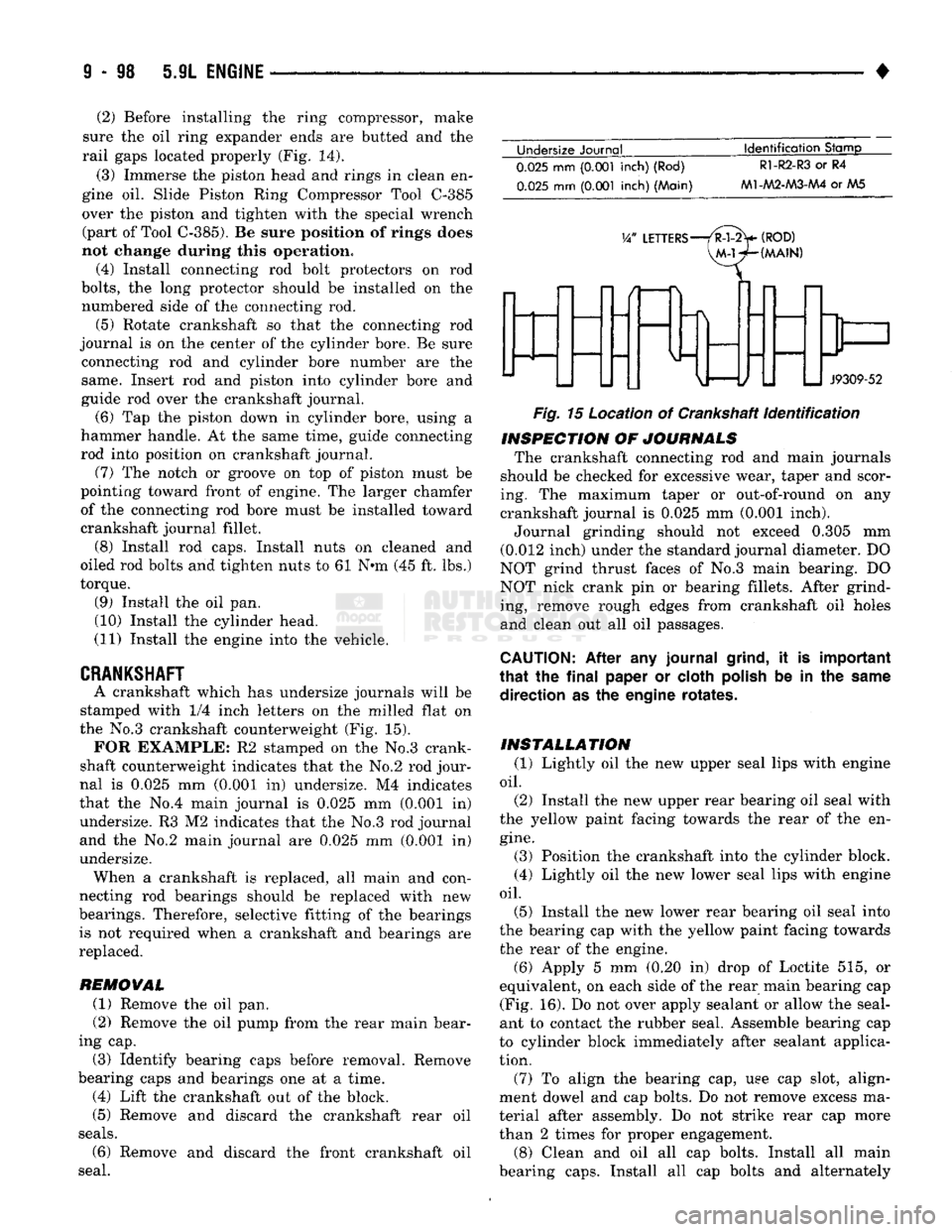
CRANKSHAFT
A crankshaft which has undersize journals will be
stamped with 1/4 inch letters on the milled flat on
the No.3 crankshaft counterweight (Fig. 15). FOR EXAMPLE: R2 stamped on the No.3 crank
shaft counterweight indicates that the No.2 rod jour
nal is 0.025 mm (0.001 in) undersize. M4 indicates
that the No.4 main journal is 0.025 mm (0.001 in) undersize. R3 M2 indicates that the No.3 rod journal
and the No.2 main journal are 0.025 mm (0.001 In)
undersize. When a crankshaft is replaced, all main and con
necting rod bearings should be replaced with new
bearings. Therefore, selective fitting of the bearings is not required when a crankshaft and bearings are
replaced.
REMOVAL
(1) Remove the oil pan.
(2) Remove the oil pump from the rear main bear
ing cap.
(3) Identify bearing caps before removal. Remove
bearing caps and bearings one at a time. (4) Lift the crankshaft out of the block.
(5) Remove and discard the crankshaft rear oil
seals.
(6) Remove and discard the front crankshaft oil
seal. Undersize Journal
Identification
Stamp
0.025
mm
(0.001
inch) (Rod)
0.025
mm
(0.001
inch) (Main)
R1-R2-R3
or R4
M1-AA2-M3-AA4
or AA5
V/
LETTERS—/R-l-2>
(ROD)
VM-WHMAIN)
J9309-52
Fig.
15 Location of Crankshaft
identification
INSPECTION
OF
JOURNALS
The crankshaft connecting rod and main journals
should be checked for excessive wear, taper and scor
ing. The maximum taper or out-of-round on any
crankshaft journal is 0.025 mm (0.001 inch).
Journal grinding should not exceed 0.305 mm
(0.012 inch) under the standard journal diameter. DO
NOT grind thrust faces of No.3 main bearing. DO
NOT nick crank pin or bearing fillets. After grind ing, remove rough edges from crankshaft oil holes
and clean out all oil passages.
CAUTION:
After any journal
grind,
it is important
that
the
final
paper or cloth
polish
be in the
same
direction as the engine rotates.
INSTALLATION
(1) Lightly oil the new upper seal lips with engine
oil.
(2) Install the new upper rear bearing oil seal with
the yellow paint facing towards the rear of the en
gine.
(3) Position the crankshaft into the cylinder block.
(4) Lightly oil the new lower seal lips with engine
oil.
(5) Install the new lower rear bearing oil seal into
the bearing cap with the yellow paint facing towards the rear of the engine. (6) Apply 5 mm (0.20 in) drop of Loctite 515, or
equivalent, on each side of the rear main bearing cap (Fig. 16). Do not over apply sealant or allow the seal
ant to contact the rubber seal. Assemble bearing cap
to cylinder block immediately after sealant applica
tion.
(7) To align the bearing cap, use cap slot, align
ment dowel and cap bolts. Do not remove excess ma
terial after assembly. Do not strike rear cap more
than 2 times for proper engagement.
(8) Clean and oil all cap bolts. Install all main
bearing caps. Install all cap bolts and alternately
Page 705 of 1502
9
- 100 5.9L
ENGINE
• When installing a new upper bearing shell, slightly
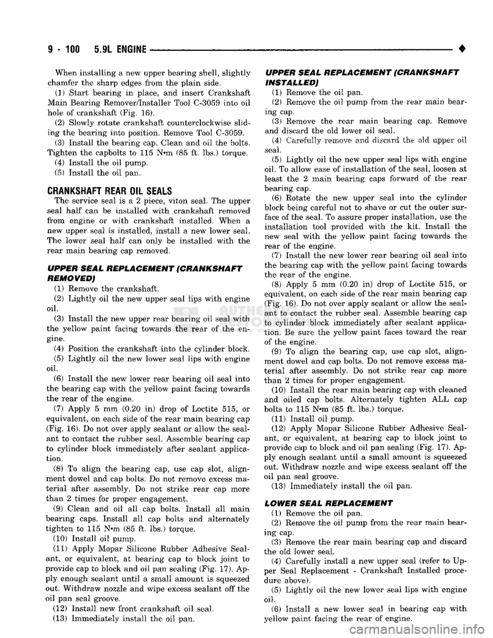
chamfer the sharp edges from the plain side. (1) Start bearing in place, and insert Crankshaft
Main Bearing Remover/Installer Tool C-3059 into oil
hole of crankshaft (Fig. 16).
(2) Slowly rotate crankshaft counterclockwise slid
ing the bearing into position. Remove Tool C-3059.
(3) Install the bearing cap. Clean and oil the bolts.
Tighten the capbolts to 115 N»m (85 ft. lbs.) torque.
(4) Install the oil pump.
(5) Install the oil pan.
CRANKSHAFT REAR
OIL
SEALS
The service seal is a 2 piece, viton seal. The upper
seal half can be installed with crankshaft removed
from engine or with crankshaft installed. When a
new upper seal is installed, install a new lower seal.
The lower seal half can only be installed with the
rear main bearing cap removed.
UPPER SEAL REPLACEMENT (CRANKSHAFT
REMOVED)
(1) Remove the crankshaft.
(2) Lightly oil the new upper seal lips with engine
oil.
(3) Install the new upper rear bearing oil seal with
the yellow paint facing towards the rear of the en
gine.
(4) Position the crankshaft into the cylinder block.
(5) Lightly oil the new lower seal lips with engine
oil.
(6) Install the new lower rear bearing oil seal into
the bearing cap with the yellow paint facing towards
the rear of the engine.
(7) Apply 5 mm (0.20 in) drop of Loctite 515, or
equivalent, on each side of the rear main bearing cap (Fig. 16). Do not over apply sealant or allow the seal
ant to contact the rubber seal. Assemble bearing cap
to cylinder block immediately after sealant applica
tion.
(8) To align the bearing cap, use cap slot, align
ment dowel and cap bolts. Do not remove excess ma
terial after assembly. Do not strike rear cap more
than 2 times for proper engagement.
(9) Clean and oil all cap bolts. Install all main
bearing caps. Install all cap bolts and alternately
tighten to 115
Nth
(85 ft. lbs.) torque. (10) Install oil pump.
(11) Apply Mopar Silicone Rubber Adhesive Seal
ant, or equivalent, at bearing cap to block joint to
provide cap to block and oil pan sealing (Fig. 17). Ap
ply enough sealant until a small amount is squeezed
out. Withdraw nozzle and wipe excess sealant off the
oil pan seal groove.
(12) Install new front crankshaft oil seal.
(13) Immediately install the oil pan. UPPER SEAL REPLACEMENT (CRANKSHAFT
INSTALLED)
(1) Remove the oil pan.
(2) Remove the oil pump from the rear main bear
ing cap. (3) Remove the rear main bearing cap. Remove
and discard the old lower oil seal. (4) Carefully remove and discard the old upper oil
seal. (5) Lightly oil the new upper seal lips with engine
oil.
To allow ease of installation of the seal, loosen at least the 2 main bearing caps forward of the rear
bearing cap.
(6) Rotate the new upper seal into the cylinder
block being careful not to shave or cut the outer sur face of the seal. To assure proper installation, use the installation tool provided with the kit. Install the
new seal with the yellow paint facing towards the
rear of the engine.
(7) Install the new lower rear bearing oil seal into
the bearing cap with the yellow paint facing towards
the rear of the engine.
(8) Apply 5 mm (0.20 in) drop of Loctite 515, or
equivalent, on each side of the rear main bearing cap (Fig. 16). Do not over apply sealant or allow the seal
ant to contact the rubber seal. Assemble bearing cap
to cylinder block immediately after sealant applica
tion. Be sure the yellow paint faces toward the rear of the engine.
(9) To align the bearing cap, use cap slot, align
ment dowel and cap bolts. Do not remove excess ma
terial after assembly. Do not strike rear cap more
than 2 times for proper engagement.
(10) Install the rear main bearing cap with cleaned
and oiled cap bolts. Alternately tighten ALL cap
bolts to 115 N*m (85 ft. lbs.) torque.
(11) Install oil pump.
(12) Apply Mopar Silicone Rubber Adhesive Seal
ant, or equivalent, at bearing cap to block joint to
provide cap to block and oil pan sealing (Fig. 17). Ap
ply enough sealant until a small amount is squeezed out. Withdraw nozzle and wipe excess sealant off the
oil pan seal groove.
(13) Immediately install the oil pan.
LOWER SEAL REPLACEMENT (1) Remove the oil pan.
(2) Remove the oil pump from the rear main bear
ing cap. (3) Remove the rear main bearing cap and discard
the old lower seal. (4) Carefully install a new upper seal (refer to Up
per Seal Replacement - Crankshaft Installed proce dure above). (5) Lightly oil the new lower seal lips with engine
oil.
(6) Install a new lower seal in bearing cap with
yellow paint facing the rear of engine.