1993 DODGE TRUCK tow
[x] Cancel search: towPage 295 of 1502
7 - 24
COOLING SYSTEM
• If the thermostat is being replaced, be sure that
the replacement is the specified thermostat for the vehicle model and engine type. Factory installed thermostat housings on 3.9L/5.2L/
5.9L engines are installed on a gasket with an anti-
stick coating. This will aid in gasket removal and
clean-up.
(1) Disconnect negative battery cable at battery.
(2) Drain cooling system until coolant level is be
low thermostat. Refer to Draining Cooling System in
this group. If not equipped with air conditioning, pro ceed to step number 4.
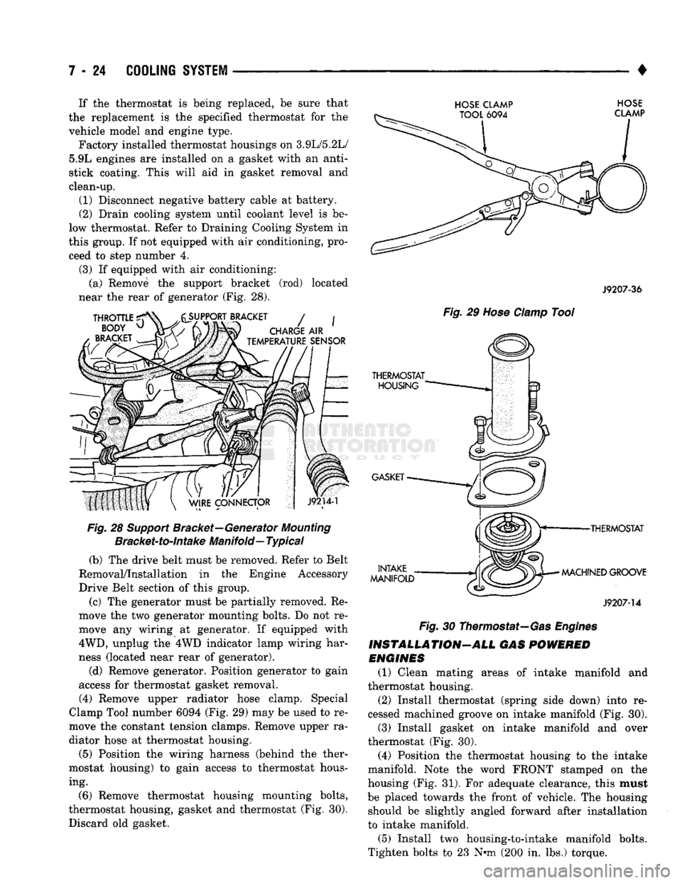
(3) If equipped with air conditioning: (a) Remove the support bracket (rod) located
near the rear of generator (Fig. 28).
Fig.
28
Support
Bracket—Generator
Mounting
Bracket-to-intake
Manifold—
Typical
(b) The drive belt must be removed. Refer to Belt
Removal/Installation in the Engine Accessory
Drive Belt section of this group.
(c) The generator must be partially removed. Re
move the two generator mounting bolts. Do not re
move any wiring at generator. If equipped with
4WD,
unplug the 4WD indicator lamp wiring har
ness (located near rear of generator).
(d) Remove generator. Position generator to gain
access for thermostat gasket removal.
(4) Remove upper radiator hose clamp. Special
Clamp Tool number 6094 (Fig. 29) may be used to re
move the constant tension clamps. Remove upper ra
diator hose at thermostat housing.
(5) Position the wiring harness (behind the ther
mostat housing) to gain access to thermostat hous ing.
(6) Remove thermostat housing mounting bolts,
thermostat housing, gasket and thermostat (Fig. 30). Discard old gasket.
HOSE CLAMP HOSE
J9207-36
Fig.
29
Hose
Clamp
Tool
•THERMOSTAT
MACHINED GROOVE
J9207-14
Fig.
30 Thermostat—Gas
Engines
INSTALLATION-ALL GAS
POWERED
ENGINES
(1) Clean mating areas of intake manifold and
thermostat housing. (2) Install thermostat (spring side down) into re
cessed machined groove on intake manifold (Fig. 30).
(3) Install gasket on intake manifold and over
thermostat (Fig. 30).
(4) Position the thermostat housing to the intake
manifold. Note the word FRONT stamped on the
housing (Fig. 31). For adequate clearance, this must
be placed towards the front of vehicle. The housing should be slightly angled forward after installation
to intake manifold.
(5) Install two housing-to-intake manifold bolts.
Tighten bolts to 23 N-m (200 in. lbs.) torque.
Page 297 of 1502
7 - 26
COOLING
SYSTEM
————
Fig. 33 Generator
Mounting
Bolts—5.9L
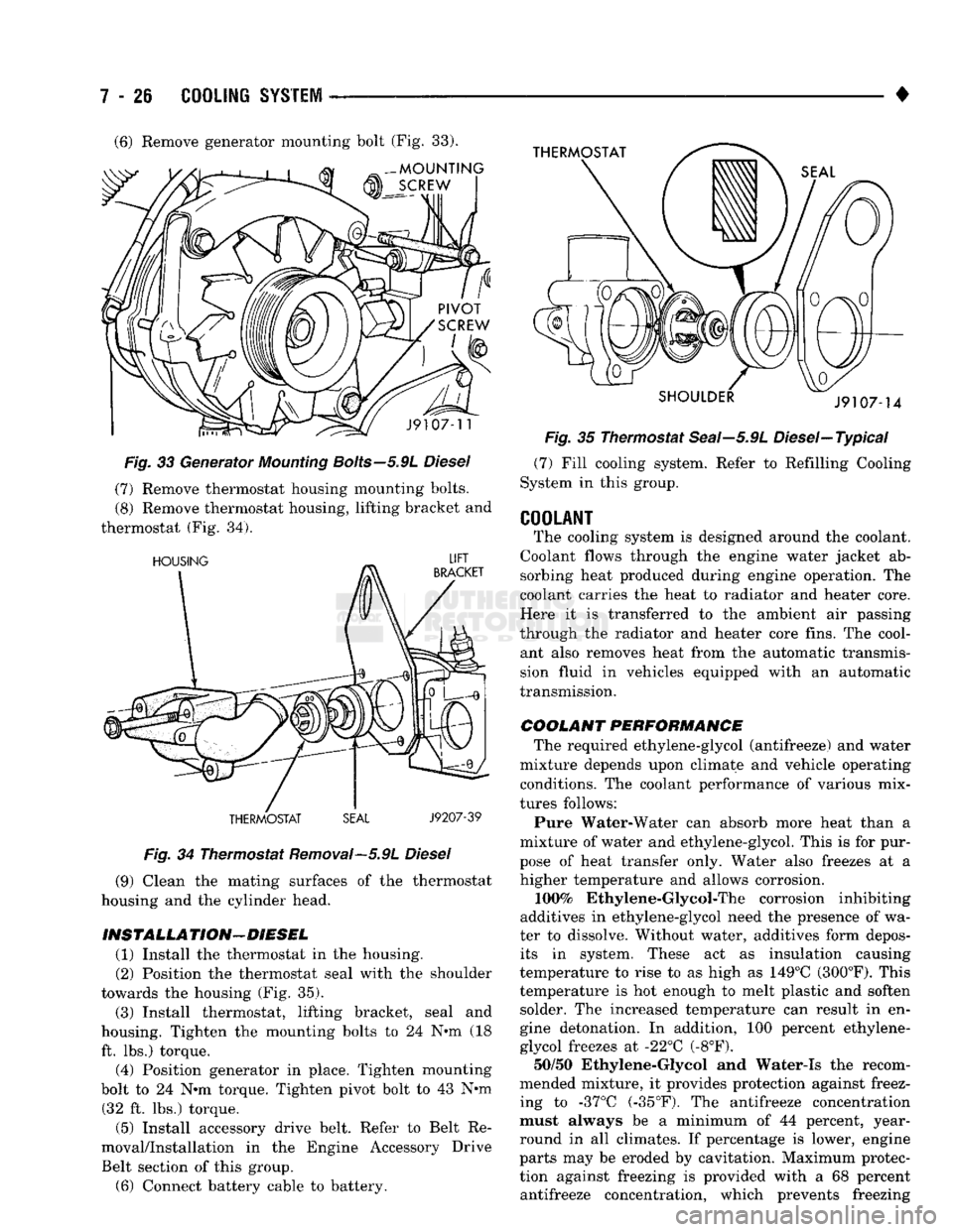
Diesel (7) Remove thermostat housing mounting bolts.
(8) Remove thermostat housing, lifting bracket and
thermostat (Fig. 34).
Fig.
34 Thermostat Removal—5.9L
Diesel
(9) Clean the mating surfaces of the thermostat
housing and the cylinder head.
INSTALLA TION—DIESEL (1) Install the thermostat in the housing.
(2) Position the thermostat seal with the shoulder
towards the housing (Fig. 35).
(3) Install thermostat, lifting bracket, seal and
housing. Tighten the mounting bolts to 24 N°m (18 ft. lbs.) torque. (4) Position generator in place. Tighten mounting
bolt to 24 N*m torque. Tighten pivot bolt to 43 N*m (32 ft. lbs.) torque.
(5) Install accessory drive belt. Refer to Belt Re
moval/Installation in the Engine Accessory Drive
Belt section of this group.
(6) Connect battery cable to battery. •
Fig.
35 Thermostat Seai—5.9L Diesel—Typical (7) Fill cooling system. Refer to Refilling Cooling
System in this group.
COOLANT
The cooling system is designed around the coolant.
Coolant flows through the engine water jacket ab sorbing heat produced during engine operation. The
coolant carries the heat to radiator and heater core.
Here it is transferred to the ambient air passing
through the radiator and heater core fins. The cool ant also removes heat from the automatic transmission fluid in vehicles equipped with an automatic
transmission.
COOLANT PERFORMANCE The required ethylene-glycol (antifreeze) and water
mixture depends upon climate and vehicle operating conditions. The coolant performance of various mix
tures follows:
Pure Water-Water can absorb more heat than a
mixture of water and ethylene-glycol. This is for pur
pose of heat transfer only. Water also freezes at a higher temperature and allows corrosion.
100%
Ethylene-Glycol-The corrosion inhibiting
additives in ethylene-glycol need the presence of wa
ter to dissolve. Without water, additives form depos its in system. These act as insulation causing
temperature to rise to as high as 149°C (300°F). This
temperature is hot enough to melt plastic and soften solder. The increased temperature can result in en
gine detonation. In addition, 100 percent ethylene-
glycol freezes at -22°C (-8°F). 50/50 Ethylene-Glycol and Water-Is the recom
mended mixture, it provides protection against freez
ing to -37°C (-35°F). The antifreeze concentration
must always be a minimum of 44 percent, year-
round in all climates. If percentage is lower, engine
parts may be eroded by cavitation. Maximum protec
tion against freezing is provided with a 68 percent antifreeze concentration, which prevents freezing (6) Remove generator mounting bolt (Fig. 33).
Page 299 of 1502
7 - 28
COOLING SYSTEM
DO NOT WASTE reusable coolant. If the solution
is clean, drain the coolant into a clean container for
reuse.
(1) Start the engine and place the heater control
temperature selector in the Full On position. Engine vacuum is needed to actuate the heater controls.
(2) Turn the ignition off. (3) Do not remove radiator cap when draining cool
ant from reserve/overflow tank. Open radiator drain
plug and when tank is empty, remove radiator cap. If
the coolant reserve/overflow tank does not drain, re fer to the Testing Cooling System for Leaks section
in this group. The coolant need not be removed from
tank unless the system is being refilled with fresh mixture.
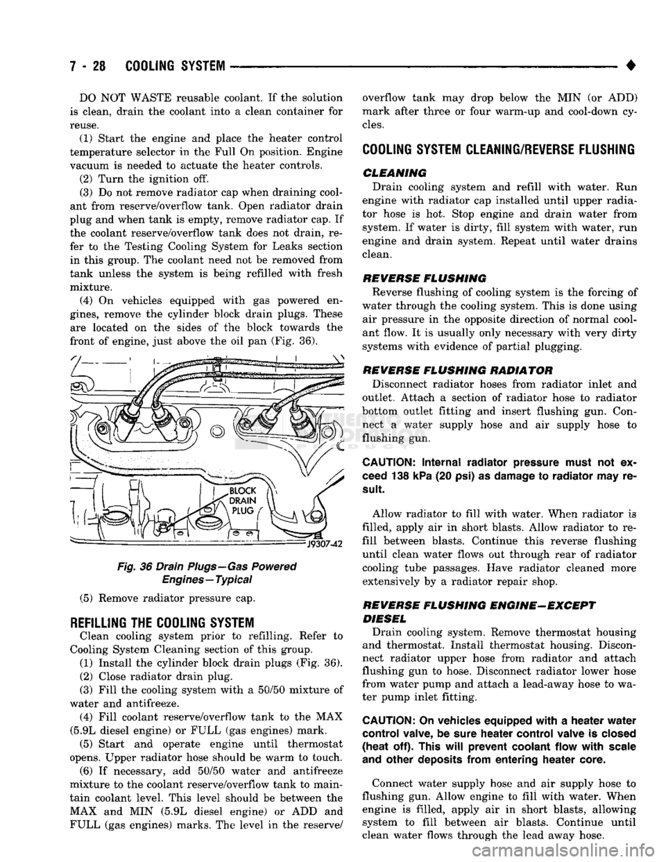
(4) On vehicles equipped with gas powered en
gines,
remove the cylinder block drain plugs. These are located on the sides of the block towards the
front of engine, just above the oil pan (Fig. 36).
Fig.
36 Drain Plugs—Gas Powered
Engines—Typical
(5) Remove radiator pressure cap.
REFILLING
THE
COOLING SYSTEM
Clean cooling system prior to refilling. Refer to
Cooling System Cleaning section of this group. (1) Install the cylinder block drain plugs (Fig. 36).
(2)
Close radiator drain plug.
(3) Fill the cooling system with a 50/50 mixture of
water and antifreeze. (4) Fill coolant reserve/overflow tank to the MAX
(5.9L diesel engine) or FULL (gas engines) mark. (5) Start and operate engine until thermostat
opens. Upper radiator hose should be warm to touch. (6) If necessary, add 50/50 water and antifreeze
mixture to the coolant reserve/overflow tank to main
tain coolant level. This level should be between the MAX and MIN (5.9L diesel engine) or ADD and FULL (gas engines) marks. The level in the reserve/ overflow tank may drop below the MIN (or ADD)
mark after three or four warm-up and cool-down cy
cles.
COOLING SYSTEM CLEANING/REVERSE FLUSHING
CLEMMING Drain cooling system and refill with water. Run
engine with radiator cap installed until upper radia
tor hose is hot. Stop engine and drain water from system. If water is dirty, fill system with water, run
engine and drain system. Repeat until water drains
clean.
REVERSE
FLUSHING
Reverse flushing of cooling system is the forcing of
water through the cooling system. This is done using air pressure in the opposite direction of normal cool
ant flow. It is usually only necessary with very dirty
systems with evidence of partial plugging.
REVERSE
FLUSHING
RADIATOR Disconnect radiator hoses from radiator inlet and
outlet. Attach a section of radiator hose to radiator
bottom outlet fitting and insert flushing gun. Con
nect a water supply hose and air supply hose to flushing gun.
CAUTION:
Internal
radiator
pressure must
not'ex
ceed 138 kPa (20 psi) as damage to
radiator
may re
sult
Allow radiator to fill with water. When radiator is
filled, apply air in short blasts. Allow radiator to re
fill between blasts. Continue this reverse flushing
until clean water flows out through rear of radiator cooling tube passages. Have radiator cleaned more extensively by a radiator repair shop.
REVERSE
FLUSHING
ENGINE-EXCEPT DIESEL Drain cooling system. Remove thermostat housing
and thermostat. Install thermostat housing. Discon
nect radiator upper hose from radiator and attach
flushing gun to hose. Disconnect radiator lower hose
from water pump and attach a lead-away hose to wa
ter pump inlet fitting.
CAUTION;
On vehicles equipped
with
a
heater
water
control
valve, be sure
heater
control
valve is closed
(heat
off). This
will
prevent
coolant
flow
with
scale
and
other
deposits
from
entering
heater
core.
Connect water supply hose and air supply hose to
flushing gun. Allow engine to fill with water. When engine is filled, apply air in short blasts, allowing system to fill between air blasts. Continue until
clean water flows through the lead away hose.
Page 308 of 1502
•
COOLING
SYSTEM
7 - 37
CAUTION:
Do not
remove
water
pump pulley-to-wa
ter
pump
bolts
(Fig. 54), This
pulley
is
under spring
tension.
(7) Remove four bolts securing fan blade assembly
to viscous fan drive (Fig. 54).
INSPECTION The fan cannot be repaired. If fan is damaged, it
must be replaced. Inspect fan as follows:
(1) Remove fan blade and viscous fan drive as an
assembly from the engine. Refer to preceding Re
moval procedure.
(2) Remove fan blade assembly from viscous fan
drive unit (four bolts).
(3) Lay fan on a flat surface with leading edge fac
ing down. With tip of blade touching flat surface, re
place fan if clearance between opposite blade and surface is greater than 2.0 mm (.090 inch). Rocking
motion of opposite blades should not exceed 2.0 mm (.090 inch). Test all blades in this manner.
WARNING:
DO NOT
ATTEMPT
TO
BEND
OR
STRAIGHTEN
FAN
BLADES
IF NOT
WITHIN
SPECI
FICATIONS.
(4) Inspect fan assembly for cracks, bends, loose
rivets or broken welds. Replace fan if any damage is
found,
CAUTION:
If fan
blade assembly
is
replaced
be
cause
of
mechanical damage,
water
pump
and
vis
cous
fan
drive should
also
be
inspected. These
components
could have been damaged
due to ex
cessive
vibration.
INSTALLATION (1) Install fan blade assembly to viscous fan drive.
Tighten bolts (Fig. 48) to 23 N*m (17 ft. lbs.) torque. (2) Position fan shroud and fan blade/viscous fan
drive assembly to vehicle as a complete unit.
(3) Install fan shroud.
(4) Install fan blade/viscous fan drive assembly to
water pump shaft (Fig. 54). (5) Install coolant reserve/overflow tank to fan
shroud. Snaps into position.
(6) Install throttle cable to fan shroud.
(7) Connect negative battery cable.
COOLING
SYSTEM
FAN-DIESEL ENGINE
REMOVAL (1) Disconnect negative battery cable from battery.
(2) Remove the fan shroud mounting bolts. Posi
tion fan shroud towards engine.
CAUTION:
Do not
remove
the fan
puHey bolts. This pulley
is
under spring tension.
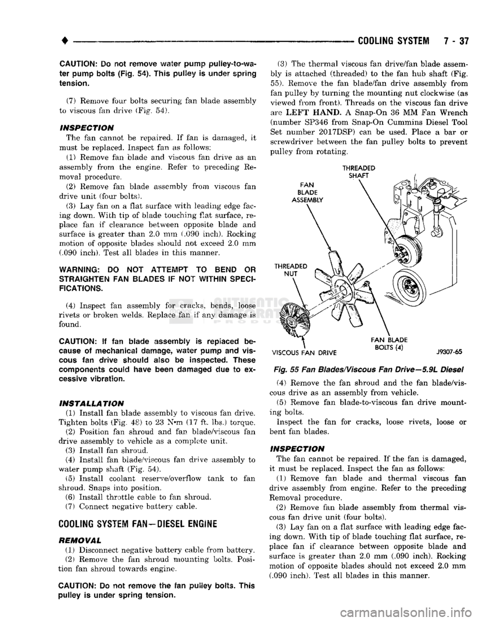
(3) The thermal viscous fan drive/fan blade assem
bly is attached (threaded) to the fan hub shaft (Fig.
55).
Remove the fan blade/fan drive assembly from
fan pulley by turning the mounting nut clockwise (as
viewed from front). Threads on the viscous fan drive are LEFT HAND. A Snap-On 36 MM Fan Wrench
(number SP346 from Snap-On Cummins Diesel Tool
Set number 2017DSP) can be used. Place a bar or
screwdriver between the fan pulley bolts to prevent
pulley from rotating.
THREADED
Fig.
55 Fan
Blades/Viscous
Fan Drive-5.9L
Diesel
(4) Remove the fan shroud and the fan blade/vis
cous drive as an assembly from vehicle.
(5) Remove fan blade-to-viscous fan drive mount
ing bolts.
Inspect the fan for cracks, loose rivets, loose or
bent fan blades.
INSPECTION The fan cannot be repaired. If the fan is damaged,
it must be replaced. Inspect the fan as follows:
(1) Remove fan blade and thermal viscous fan
drive assembly from engine. Refer to the preceding
Removal procedure.
(2) Remove fan blade assembly from thermal vis
cous fan drive unit (four bolts). (3) Lay fan on a flat surface with leading edge fac
ing down. With tip of blade touching flat surface, re
place fan if clearance between opposite blade and surface is greater than 2.0 mm (.090 inch). Rocking
motion of opposite blades should not exceed 2.0 mm (.090 inch). Test all blades in this manner.
Page 358 of 1502
•
IGNITION
SYSTEMS
80 - 7
DIAGNOSTICS/SERW1CE
PROCEDURES
INDEX
page
Automatic Shut Down (ASD) Relay
7
Camshaft Position
Sensor
Test
...............
7
Crankshaft Position
Sensor
Test
8
Distributor
Cap
8
Distributor
Rotor
8
Engine
Coolant Temperature
Sensor
Test
10
General
Information
7
Ignition
Coil
8
Ignition
Secondary
Circuit
Diagnosis
10
GENERAL
INFORMATION
This section
of the
group, Diagnostics/Service Pro
cedures, will discuss basic ignition system diagnos
tics
and
service adjustments. For system operation
and
component identification,
refer
to the
Component Identification/System Opera
tion section
of
this group. For removal
or
installation
of
ignition system com
ponents, refer
to the
Component Removal/Installa
tion section
of
this group. For other useful information, refer
to
On-Board
Di
agnostics
in the
General Diagnosis sections
of
Group
14,
Fuel System
in
this manual. For operation
of the DRB II
Diagnostic Scan Tool,
refer
to the
appropriate Powertrain Diagnostic Proce
dures service manual.
AUTOMATIC SHUT DOWN
(ASD)
RELAY
Refer
to
Relays—Operation/Testing
in the
Group
14,
Fuel System section
of
this service manual.
CAMSHAFT POSITION SENSOR TEST
The camshaft position sensor
is
located
in the
dis
tributor
on all
engines. To perform
a
complete test
of
this sensor
and its
circuitry, refer
to the DRB II
diagnostic scan tool.
Also refer
to the
appropriate Powertrain Diagnostics
Procedures manual.
To
test
the
sensor only, refer
to
the following: For this test,
an
analog (non-digital) voltmeter
is needed.
Do not
remove
the
distributor connector from
the
distributor. Using small paper clips, insert
them into
the
backside
of the
distributor wire har ness connector
to
make contact with
the
terminals.
Be sure that
the
connector
is not
damaged when
in
serting
the
paper clips. Attach voltmeter leads
to
these paper clips. (1) Connect
the
positive (
+
)
voltmeter lead into
the sensor output wire. This
is at
done
the
distribu tor wire harness connector.
For
wire identification,
refer
to
Group
8W,
Wiring Diagrams.
page
Ignition
Timing
12
Intake Manifold Charge
Air
Temperature
Sensor
Test
12
Manifold Absolute Pressure (MAP)
Sensor
Test
. 12
Oxygen
Sensor
Tests
17
Powertrain Control Module (PCM)
............
14
Spark
Plug Secondary Cables
16
Spark
Plugs
............................
14
Throttle
Position
Sensor
Test
17
(2) Connect
the
negative
(-)
voltmeter lead into
the
ground wire.
For
wire identification, refer
to
Group
8W, Wiring Diagrams.
(3)
Set the
voltmeter
to the 15
Volt
DC
scale. (4) Remove distributor
cap
from distributor
(two
screws). Rotate (crank)
the
engine until
the
distribu
tor rotor
is
pointed towards
the
rear
of
vehicle.
The
movable pulse ring should
now be
within
the
sensor
pickup.
(5) Turn ignition
key to ON
position. Voltmeter
should read approximately
5.0
volts.
(6)
If
voltage
is not
present, check
the
voltmeter
leads
for a
good connection.
(7)
If
voltage
is
still
not
present, check
for
voltage
at
the
supply wire.
For
wire identification, refer
to
Group
8W,
Wiring Diagrams.
(8)
If
voltage
is not
present
at
supply wire, check
for voltage
at
pin-7
of
powertrain control module (PCM) 60-way connector. Leave
the PCM
connector
connected
for
this test. (9)
If
voltage
is
still
not
present, perform vehicle
test using
the DRB II
diagnostic scan tool. (10)
If
voltage
is
present
at
pin-7,
but not at the
supply wire: (a) Check continuity between
the
supply wire.
This
is
checked between
the
distributor connector and pin-7
at the PCM. If
continuity
is not
present,
repair
the
harness
as
necessary. (b) Check
for
continuity between
the
camshaft
position sensor output wire
and
pin-44
at the PCM.
If continuity
is not
present, repair
the
harness
as
necessary. (c) Check
for
continuity between
the
ground cir
cuit wire
at the
distributor connector
and
ground.
If continuity
is not
present, repair
the
harness
as
necessary. (11) While observing
the
voltmeter, crank
the en
gine with ignition switch.
The
voltmeter needle should fluctuate between
0 and 5
volts while
the en
gine
is
cranking. This verifies that
the
camshaft
po
sition sensor
in the
distributor
is
operating properly
and
a
sync pulse signal
is
being generated.
Page 359 of 1502
8D
- 8
IGNITION
SYSTEMS
• If sync pulse signal is not present, replacement of
the camshaft position sensor is necessary. For removal or installation of ignition system com
ponents, refer to the Component Removal/Installa
tion section of this group.
For system operation and component identification,
refer to the Component Identification/System Opera
tion section of this group.
CRANKSHAFT POSITION
SENSOR
TEST
To perform a complete test of this sensor and its
circuitry, refer to the DRB II diagnostic scan tool.
Also refer to the appropriate Powertrain Diagnostics
Procedures manual. To test the sensor only, refer to
the following: The sensor is located on the top of cylinder block
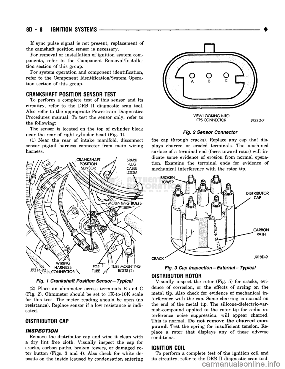
near the rear of right cylinder head (Fig. 1). (1) Near the rear of intake manifold, disconnect
sensor pigtail harness connector from main wiring
harness. Fig. 1 Crankshaft Position Sensor—Typical
(2) Place an ohmmeter across terminals B and C
(Fig. 2). Ohmmeter should be set to lK-to-lOK scale
for this test. The meter reading should be open (no
resistance). Replace sensor if a low resistance is indi cated.
DISTRIBUTOR
CAP INSPECTION Remove the distributor cap and wipe it clean with
a dry lint free cloth. Visually inspect the cap for
cracks, carbon paths, broken towers, or damaged ro
tor button (Figs. 3 and 4). Also check for white de
posits on the inside (caused by condensation entering VIEW LOOKING INTO
CPS
CONNECTOR
J938D-7
Fig. 2 Sensor Connector the cap through cracks). Replace any cap that dis
plays charred or eroded terminals. The machined surface of a terminal end (faces toward rotor) will in
dicate some evidence of erosion from normal opera
tion. Examine the terminal ends for evidence of mechanical interference with the rotor tip. Fig. 3 Cap Inspection—External—Typical
DISTRIBUTOR ROTOR
Visually inspect the rotor (Fig. 5) for cracks, evi
dence of corrosion, or the effects of arcing on the
metal tip. Also check for evidence of mechanical in
terference with the cap. Some charring is normal on
the end of the metal tip. The silicone-dielectric-var nish-compound applied to the rotor tip for radio in
terference noise suppression, will appear charred.
This is normal. Do not remove the charred com pound. Test the spring for insufficient tension. Re
place a rotor that displays any of these adverse conditions.
IGNITION COIL
To perform a complete test of the ignition coil and
its circuitry, refer to the DRB II diagnostic scan tool.
Page 361 of 1502
8D
- 10
IGNITION
SYSTEMS
• Arcing at the tower will carbonize the cable boot,
which if it is connected to a new ignition coil, will cause the coil to fail. If the secondary coil cable shows any signs of dam
age,
it should be replaced with a new cable and new
terminal. Carbon tracking on the old cable can cause
arcing and the failure of a new ignition coil.
ENGINE
COOLANT
TEMPERATURE
SENSOR
TEST
To perform a complete test of this sensor and its
circuitry, refer to the DRB II diagnostic scan tool.
Also refer to the appropriate Powertrain Diagnostics
Procedures manual. To test the sensor only, refer to
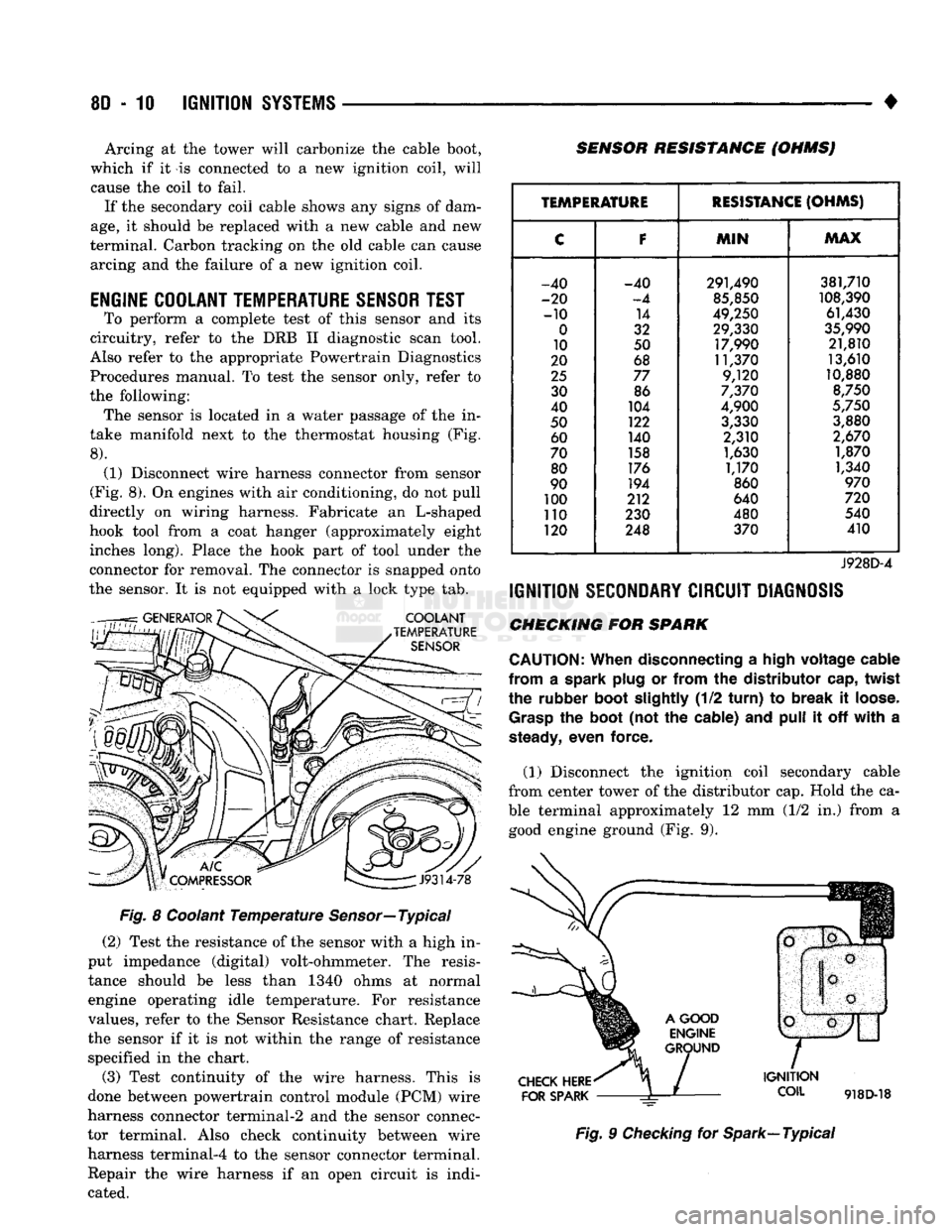
the following: The sensor is located in a water passage of the in
take manifold next to the thermostat housing (Fig.
8).
(1) Disconnect wire harness connector from sensor
(Fig. 8). On engines with air conditioning, do not pull
directly on wiring harness. Fabricate an L-shaped
hook tool from a coat hanger (approximately eight inches long). Place the hook part of tool under the
connector for removal. The connector is snapped onto
the sensor. It is not equipped with a lock type tab.
COOLANT
TEMPERATURE
SENSOR
SENSOR RESISTANCE (OHMSJ
V
J9314-78
Fig. 8 Coolant Temperature Sensor—Typical (2) Test the resistance of the sensor with a high in
put impedance (digital) volt-ohmmeter. The resis tance should be less than 1340 ohms at normal
engine operating idle temperature. For resistance
values, refer to the Sensor Resistance chart. Replace
the sensor if it is not within the range of resistance specified in the chart.
(3) Test continuity of the wire harness. This is
done between powertrain control module (PCM) wire
harness connector terminal-2 and the sensor connec
tor terminal. Also check continuity between wire harness terminal-4 to the sensor connector terminal. Repair the wire harness if an open circuit is indi
cated.
TEMPERATURE
RESISTANCE
(OHMS)
C
F
MIN
MAX
-40 -40 291,490 381,710
-20
-4
85,850
108,390
-10 14
49,250 61,430
0
32 29,330
35,990
10 50 17,990 21,810
20 68 11,370 13,610
25
77 9,120 10,880
30 86
7,370
8,750
40 104
4,900
5,750
50 122
3,330 3,880
60 140 2,310
2,670
70 158
1,630 1,870
80 176
1,170 1,340
90 194
860
970
100 212 640
720
110 230 480 540
120 248 370 410
J928D-4
IGNITION
SECONDARY
CIRCUIT
DIAGNOSIS
CHECKING FOR SPARK
CAUTION:
When
disconnecting a
high
voltage
cable
from
a spark
plug
or
from
the
distributor
cap,
twist
the rubber
boot
slightly
(1/2
turn)
to
break
it
loose.
Grasp
the
boot
(not the cable) and
pull
it off
with
a
steady,
even force.
(1) Disconnect the ignition coil secondary cable
from center tower of the distributor cap. Hold the ca
ble terminal approximately 12 mm (1/2 in.) from a good engine ground (Fig. 9).
CHECK
HERE
FOR
SPARK
IGNITION
COIL
918D-18
Fig. 9 Checking for Spark—Typical
Page 367 of 1502
8D
- 16
IGNITION
SYSTEMS
• other operating conditions are causing engine over
heating. (The heat range rating refers to the operat
ing temperature of a particular type spark plug.
Spark plugs are designed to operate within specific
temperature ranges. This depends upon the thickness and length of the center electrodes porcelain insula
tor.)
GROUND
ELECTRODE
CENTER
ELECTRODE
DISSOLVED
J908D-14 Fig. 26 Preignition Damage
SPARK
PLUG
OVERHEATING
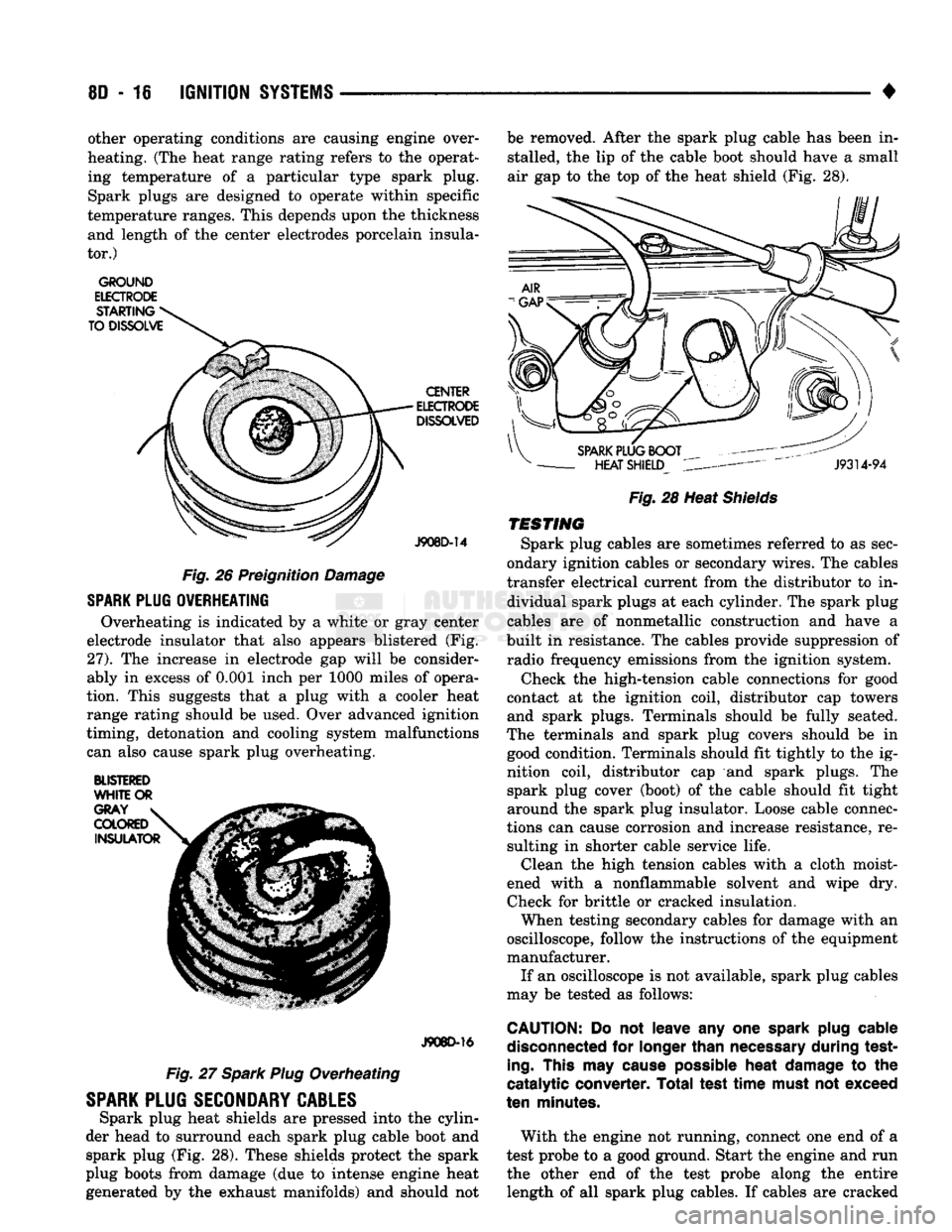
Overheating is indicated by a white or gray center
electrode insulator that also appears blistered (Fig.
27).
The increase in electrode gap will be consider
ably in excess of 0.001 inch per 1000 miles of opera
tion. This suggests that a plug with a cooler heat
range rating should be used. Over advanced ignition
timing, detonation and cooling system malfunctions can also cause spark plug overheating.
BLISTERED
WHITE
OR
J908D-16
Fig. 27 Spark Plug Overheating
SPARK
PLUG
SECONDARY
CABLES
Spark plug heat shields are pressed into the cylin
der head to surround each spark plug cable boot and spark plug (Fig. 28). These shields protect the spark
plug boots from damage (due to intense engine heat
generated by the exhaust manifolds) and should not be removed. After the spark plug cable has been in
stalled, the lip of the cable boot should have a small
air gap to the top of the heat shield (Fig. 28).
Fig.
28 Heat
Shields
TESTING
Spark plug cables are sometimes referred to as sec
ondary ignition cables or secondary wires. The cables
transfer electrical current from the distributor to in dividual spark plugs at each cylinder. The spark plug
cables are of nonmetallic construction and have a
built in resistance. The cables provide suppression of radio frequency emissions from the ignition system.
Check the high-tension cable connections for good
contact at the ignition coil, distributor cap towers and spark plugs. Terminals should be fully seated.
The terminals and spark plug covers should be in good condition. Terminals should fit tightly to the ig
nition coil, distributor cap and spark plugs. The spark plug cover (boot) of the cable should fit tight
around the spark plug insulator. Loose cable connec
tions can cause corrosion and increase resistance, re sulting in shorter cable service life. Clean the high tension cables with a cloth moist
ened with a nonflammable solvent and wipe dry.
Check for brittle or cracked insulation. When testing secondary cables for damage with an
oscilloscope, follow the instructions of the equipment
manufacturer. If an oscilloscope is not available, spark plug cables
may be tested as follows:
CAUTION:
Do not leave any one
spark
plug
cable
disconnected
for
longer
than
necessary
during test
ing.
This
may
cause
possible
heat
damage
to the
catalytic converter. Total test
time
must
not exceed
ten
minutes.
With the engine not running, connect one end of a
test probe to a good ground. Start the engine and run the other end of the test probe along the entire length of all spark plug cables. If cables are cracked