1993 DODGE TRUCK tow
[x] Cancel search: towPage 119 of 1502
2
- 66
FRONT
SUSPENSION
AND
AXLE
•
PINION
GEAR
DEPTH
MEASUREMENT
AND
ADJUSTMENT
WITH
TOOL
SET
D-116 The following gear depth measurement and adjust
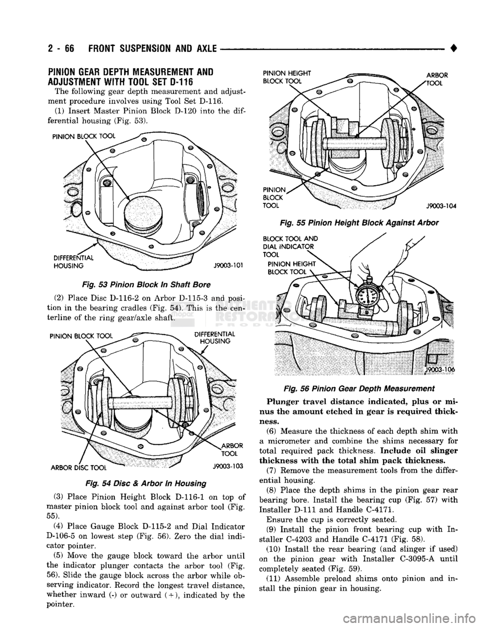
ment procedure involves using Tool Set D-116. (1) Insert Master Pinion Block D-120 into the
dif
ferential housing (Fig. 53).
Fig.
53
Pinion
Block
In Shaft
Bore
(2) Place Disc D-116-2 on Arbor D-115-3 and posi
tion in the bearing cradles (Fig. 54). This is the cen
terline of the ring gear/axle shaft.
Fig.
54
Disc
&
Arbor
In
Housing
(3) Place Pinion Height Block D-116-1 on top of
master pinion block tool and against arbor tool (Fig.
55).
(4) Place Gauge Block D-115-2 and Dial Indicator
D-106-5 on lowest step (Fig. 56). Zero the dial indi
cator pointer.
(5) Move the gauge block toward the arbor until
the indicator plunger contacts the arbor tool (Fig.
56).
Slide the gauge block across the arbor while ob
serving indicator. Record the longest travel distance,
whether inward (-) or outward
(
+ ), indicated by the
pointer.
Fig.
55
Pinion
Height
Block
Against
Arbor
Fig.
56
Pinion
Gear Depth Measurement
Plunger travel distance indicated, plus or mi
nus the amount etched in gear is required thick
ness.
(6) Measure the thickness of each depth shim with
a micrometer and combine the shims necessary for
total required pack thickness. Include oil slinger
thickness with the total shim pack thickness.
(7) Remove the measurement tools from the differ
ential housing.
(8) Place the depth shims in the pinion gear rear
bearing bore. Install the bearing cup (Fig. 57) with
Installer D-lll and Handle C-4171.
Ensure the cup is correctly seated. (9) Install the pinion front bearing cup with In
staller C-4203 and Handle C-4171 (Fig. 58). (10) Install the rear bearing (and slinger if used)
on the pinion gear with Installer C-3095-A until
completely seated (Fig. 59).
(11) Assemble preload shims onto pinion and in
stall the pinion gear in housing.
Page 127 of 1502
2
- 74
FRONT SUSPENSION AND AXLE
DRIVE
SIDE
OF RING
GEAR
TEETH
HEEL
TOE
COAST
SIDE
OF RING
GEAR
TEETH TOE
HEEL
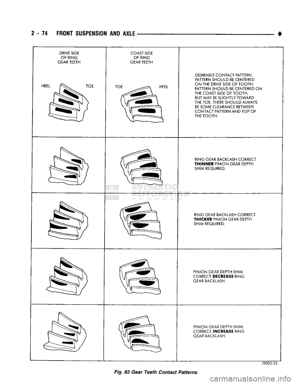
DESIRABLE
CONTACT PATTERN.
PATTERN SHOULD BE CENTERED
ON THE DRIVE SIDE OF TOOTH.
PATTERN SHOULD BE CENTERED
ON
THE COAST
SIDE
OF TOOTH, BUT MAY BE SLIGHTLY TOWARD
THE TOE. THERE SHOULD ALWAYS
BE
SOME CLEARANCE BETWEEN
CONTACT PATTERN AND TOP
OF
THE TOOTH.
RING GEAR
BACKLASH
CORRECT.
THINNER
PINION GEAR DEPTH
SHIM REQUIRED.
RING GEAR
BACKLASH
CORRECT.
THICKER
PINION GEAR DEPTH SHIM REQUIRED.
PINION GEAR DEPTH SHIM
CORRECT
DECREASE
RING
GEAR
BACKLASH.
PINION GEAR DEPTH SHIM
CORRECT
INCREASE
RING
GEAR
BACKLASH.
Fig.
83 Gear Teeth Contact Patterns
J9003-24
Page 135 of 1502
3
- 6
REAR SUSPENSION
AND
AXLE
•
NUT PIPE
SOCKET
WRENCH
(DRIVER)
FLAT
THREADED
WASHER
ROD
J8917-20
Fig.
6
Spring
Eye
Bushing
Removal
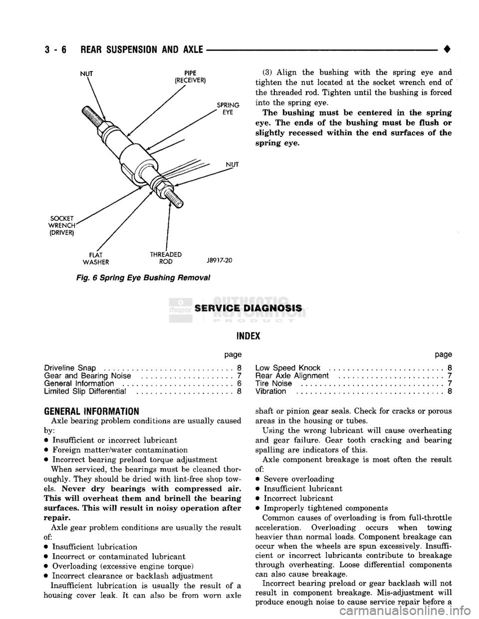
(3) Align
the
bushing with
the
spring
eye and
tighten
the nut
located
at the
socket wrench
end of
the threaded
rod.
Tighten until
the
bushing
is
forced into
the
spring
eye.
The bushing must
be
centered
in the
spring
eye.
The
ends
of the
bushing must
be
flush
or
slightly recessed within
the end
surfaces
of the
spring
eye.
8ERW1GE DIAGNOSIS
INDEX
page
Driveline
Snap
8
Gear
and
Bearing Noise
7
General
Information
6
Limited
Slip
Differential
8
page
Low Speed Knock
.........................
8
Rear
Axle
Alignment
.......................
7
Tire
Noise
7
Vibration
8
GENERAL INFORMATION
Axle bearing problem conditions
are
usually caused
by: • Insufficient
or
incorrect lubricant
• Foreign matter/water contamination
• Incorrect bearing preload torque adjustment When serviced,
the
bearings must
be
cleaned thor
oughly. They should
be
dried with lint-free shop tow
els.
Never
dry
bearings with compressed
air.
This will overheat them
and
brinell
the
bearing surfaces. This will result
in
noisy operation after
repair. Axle gear problem conditions
are
usually
the
result
of:
• Insufficient lubrication
• Incorrect
or
contaminated lubricant
• Overloading (excessive engine torque)
• Incorrect clearance
or
backlash adjustment Insufficient lubrication
is
usually
the
result
of a
housing cover leak.
It can
also
be
from worn axle shaft
or
pinion gear seals. Check
for
cracks
or
porous
areas
in the
housing
or
tubes.
Using
the
wrong lubricant will cause overheating
and gear failure. Gear tooth cracking
and
bearing
spalling
are
indicators
of
this.
Axle component breakage
is
most often
the
result
of:
• Severe overloading
• Insufficient lubricant
• Incorrect lubricant • Improperly tightened components
Common causes
of
overloading
is
from full-throttle
acceleration. Overloading occurs when towing
heavier than normal loads. Component breakage
can
occur when
the
wheels
are
spun excessively. Insuffi
cient
or
incorrect lubricants contribute
to
breakage
through overheating. Loose differential components can also cause breakage. Incorrect bearing preload
or
gear backlash will
not
result
in
component breakage. Mis-adjustment will
produce enough noise
to
cause service repair before
a
Page 142 of 1502
•
REAR SUSPENSION
AND
AXLE
3 - 13
SEALANT
1/16-TO
3/32-INCH
(1.59-TO
38-AAM)
THICK
BEAD
DIFFERENTIAL HOUSING
COVER
(TYPICAL)
J9003-85 Fig, 2 Sealant On Homing
Cower
PINION
GEAR
MATE
SHAFT
O
DIFFERENTIAL CASE
LOCK
SCREW
J9003-110
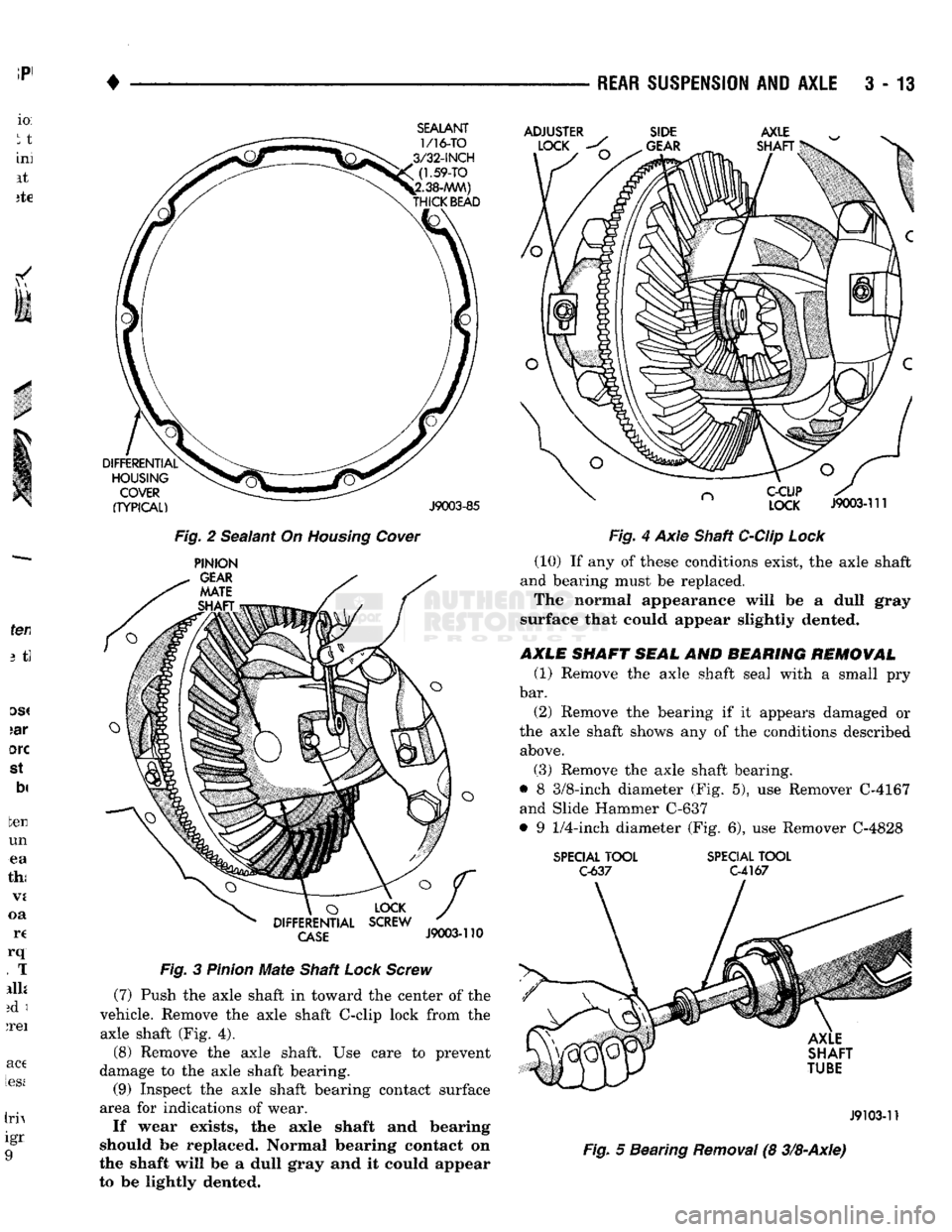
Fig. 3 Pinion Mate Shaft Lock Screw (7) Push the axle shaft in toward the center of the
vehicle. Remove the axle shaft C-clip lock from the axle shaft (Fig. 4).
(8) Remove the axle shaft. Use care to prevent
damage to the axle shaft bearing.
(9)
Inspect the axle shaft bearing contact surface
area for indications of wear. if
wear exists,
the
axle shaft
and
bearing
should be
replaced. Normal bearing
contact on
the shaft
will
be a dull gray and it
could appear
to be lightly
dented.
ADJUSTER
, SIDE
LOCK
^
GEAR
AXLE
SHAFT
•!
C-CLIP LOCK
J9003-111
Fig.
4 Axle Shaft C-Clip
Lock
(10) If any of these conditions exist, the axle shaft
and bearing must be replaced.
The normal appearance will be a dull gray
surface that could appear slightly dented.
AXLE SHAFT SEAL AND BEARING REMOVAL (1) Remove the axle shaft seal with a small pry
bar.
(2) Remove the bearing if it appears damaged or
the axle shaft shows any of the conditions described above. (3) Remove the axle shaft bearing.
• 8 3/8-inch diameter (Fig. 5), use Remover C-4167 and Slide Hammer C-637
• 9
1/4-inch
diameter (Fig. 6), use Remover C-4828
SPECIAL
TOOL
C-637
SPECIAL
TOOL
C-4167
AXLE
SHAFT
TU1E
J9103-11
Fig.
5 Bearing
Removal
(8
3/8-Axle)
Page 153 of 1502
3
- 26
REAR SUSPENSION
AND
AXLE
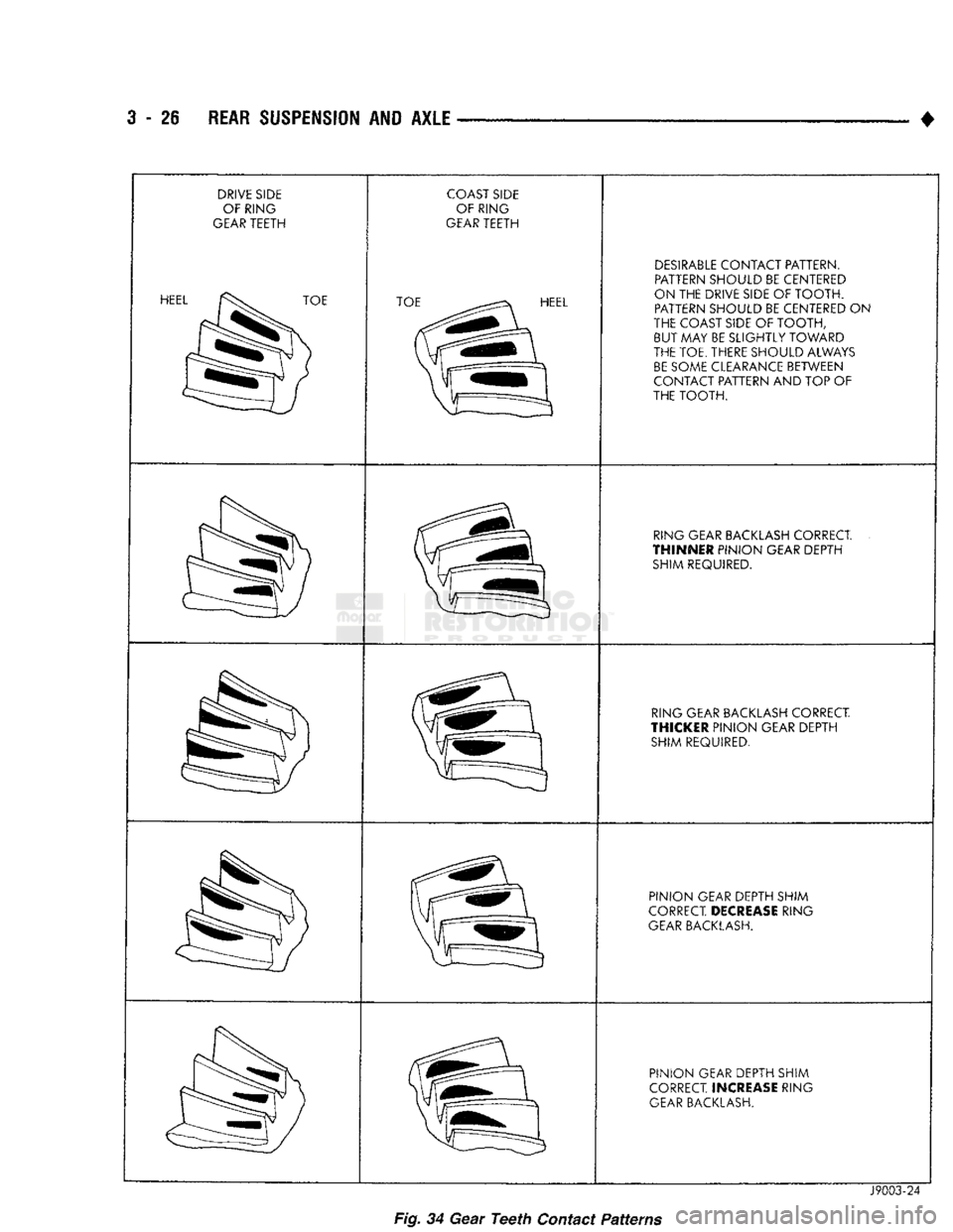
DRIVE SIDE
OF RING
GEAR TEETH HEEL
TOE COAST SIDE
OF RING
GEAR TEETH TOE
HEEL DESIRABLE CONTACT PATTERN.
PATTERN SHOULD
BE
CENTERED
ON
THE
DRIVE SIDE
OF
TOOTH. PATTERN SHOULD
BE
CENTERED
ON
THE COAST SIDE
OF
TOOTH, BUT
MAY
BE SLIGHTLY TOWARD
THE TOE. THERE SHOULD ALWAYS BE SOME CLEARANCE BETWEEN
CONTACT PATTERN
AND TOP
OF
THE TOOTH.
RING GEAR BACKLASH CORRECT.
THINNER
PINION GEAR DEPTH SHIM REQUIRED.
RING GEAR BACKLASH CORRECT.
THICKER
PINION GEAR DEPTH SHIM REQUIRED.
PINION GEAR DEPTH SHIM
CORRECT.
DECREASE
RING
GEAR BACKLASH.
PINION GEAR DEPTH SHIM
CORRECT.
INCREASE
RING
GEAR BACKLASH.
Fig.
34
Gear
Teeth
Contact
Patterns
J9003-24
Page 168 of 1502
•
REAR SUSPENSION
AND
AXLE
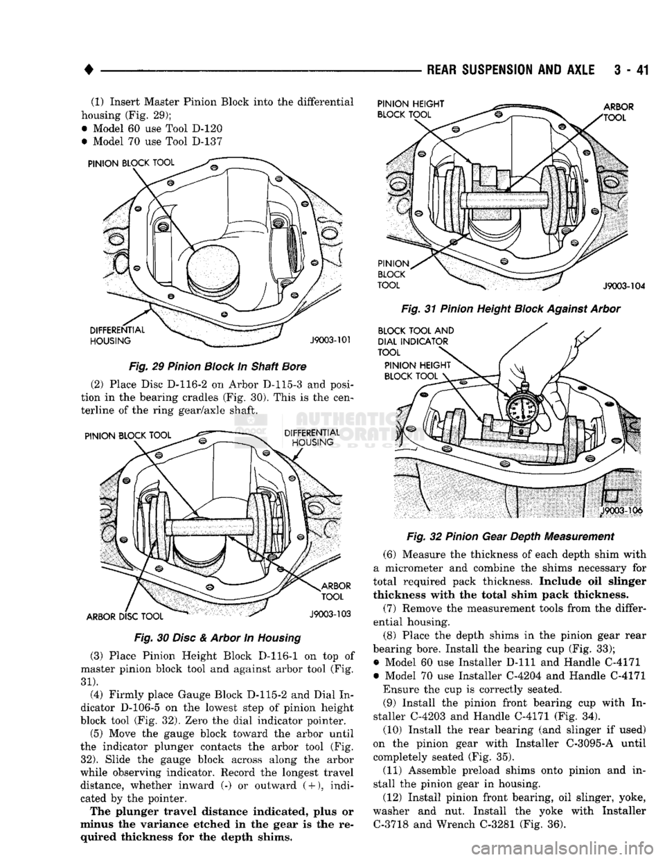
3 - 41 (1) Insert Master Pinion Block into the differential
housing (Fig. 29);
• Model 60 use Tool D-120
• Model 70 use Tool D-137
Fig.
29
Pinion
Block
In Shaft
Bore
(2) Place Disc D-116-2 on Arbor D-115-3 and posi
tion in the bearing cradles (Fig. 30). This is the cen
terline of the ring gear/axle shaft.
Fig.
30
Disc
&
Arbor
In
Housing
(3) Place Pinion Height Block D-116-1 on top of
master pinion block tool and against arbor tool (Fig.
31).
(4) Firmly place Gauge Block D-115-2 and Dial In
dicator D-106-5 on the lowest step of pinion height
block tool (Fig. 32). Zero the dial indicator pointer.
(5) Move the gauge block toward the arbor until
the indicator plunger contacts the arbor tool (Fig.
32).
Slide the gauge block across along the arbor
while observing indicator. Record the longest travel distance, whether inward (-) or outward
(
+
),
indi
cated by the pointer.
The plunger travel distance indicated, plus or
minus the variance etched in the gear is the re quired thickness for the depth shims.
Fig.
31
Pinion
Height
Block
Against
Arbor
Fig.
32
Pinion
Gear Depth Measurement
(6) Measure the thickness of each depth shim with
a micrometer and combine the shims necessary for
total required pack thickness. Include oil slinger
thickness with the total shim pack thickness.
(7) Remove the measurement tools from the differ
ential housing.
(8) Place the depth shims in the pinion gear rear
bearing bore. Install the bearing cup (Fig. 33);
• Model 60 use Installer
D-lll
and Handle C-4171
• Model 70 use Installer C-4204 and Handle C-4171 Ensure the cup is correctly seated. (9) Install the pinion front bearing cup with In
staller C-4203 and Handle C-4171 (Fig. 34).
(10) Install the rear bearing (and slinger if used)
on the pinion gear with Installer C-3095-A until
completely seated (Fig. 35).
(11) Assemble preload shims onto pinion and in
stall the pinion gear in housing.
(12) Install pinion front bearing, oil slinger, yoke,
washer and nut. Install the yoke with Installer C-3718 and Wrench C-3281 (Fig. 36).
Page 176 of 1502
•
REAR SUSPENSION AND AXLE 3 - 49
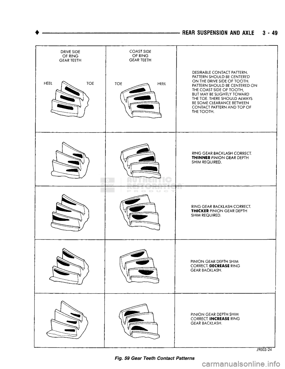
DRIVE SIDE OF RING
GEAR TEETH
HEE^^^^^^^TOE COAST SIDE
OF RING
GEAR TEETH
TOE^^^^^^^^^EL DESIRABLE CONTACT PATTERN.
PATTERN SHOULD BE CENTERED
ON THE DRIVE SIDE
OF
TOOTH. PATTERN SHOULD BE CENTERED
ON
THE COAST SIDE
OF
TOOTH, BUT MAY BE SLIGHTLY TOWARD
THE TOE. THERE SHOULD ALWAYS BE SOME CLEARANCE BETWEEN
CONTACT PATTERN
AND
TOP
OF
THE TOOTH.
RING GEAR BACKLASH CORRECT
THINNER
PINION GEAR DEPTH SHIM REQUIRED.
RING GEAR BACKLASH CORRECT
THICKER
PINION GEAR DEPTH SHIM REQUIRED.
PINION GEAR DEPTH SHIM
CORRECT
DECREASE
RING
GEAR BACKLASH.
PINION GEAR DEPTH SHIM
CORRECT.
INCREASE
RING
GEAR BACKLASH.
J9003-24
Fig. 59 Gear
Teeth
Contact
Patterns
Page 179 of 1502
3
- 52
REAR SUSPENSION
AND
AXLE
DISASSEMBLY
Service to the Trac-Lok differential requires the
use of Tool Set C-4487 (J-23781). Refer to differential
overhaul in the Model 60 section for differential case
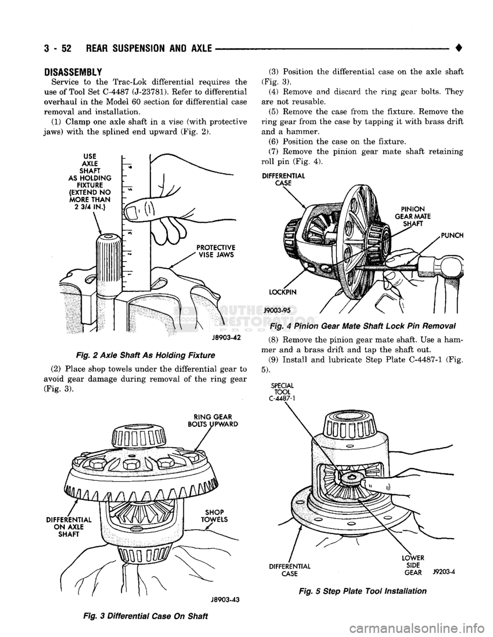
removal and installation. (1) Clamp one axle shaft in a vise (with protective
jaws) with the splined end upward (Fig. 2).
USE
AXLE
SHAFT
AS
HOLDING
FIXTURE
(EXTEND
NO
MORE
THAN
2
3/4 IN.)
J8903-42
~
Fig. 2 Axle Shaft As
Holding
Fixture
(2)
Place shop towels under the differential gear to
avoid gear damage during removal of the ring gear (Fig. 3).
RING GEAR
BOLTS UPWARD
DIFFERENTIAL ON AXLE
SHAFT
(3) Position the differential case on the axle shaft
(Fig. 3). (4) Remove and discard the ring gear bolts. They
are not reusable.
(5) Remove the case from the fixture. Remove the
ring gear from the case by tapping it with brass drift and a hammer.
(6)
Position the case on the fixture.
(7) Remove the pinion gear mate shaft retaining
roll pin (Fig. 4).
DIFFERENTIAL
CASE
PINION
GEAR
MATE SHAFT
PUNCH
LOCKPIN
J9003-95
Fig. 4
Pinion
Gear Mate Shaft
Lock
Pin
Removal
(8) Remove the pinion gear mate shaft. Use a ham
mer and a brass drift and tap the shaft out.
(9)
Install and lubricate Step Plate C-4487-1 (Fig.
5).
SPECIAL
TOOL
C-4487-1
DIFFERENTIAL
CASE
LOWER
SIDE
GEAR
J9203-4
J8903-43
Fig.
5
Step
Plate
Tool
Installation
Fig.
3
Differential
Case
On Shaft