1993 DODGE TRUCK display
[x] Cancel search: displayPage 878 of 1502
•
FUEL SYSTEM
14 - 59
fill
DHADn
HIAf5MflCTipQ
/f|Rn
The powertrain control module (PCM) has been
programmed to monitor many different circuits of the
fuel injection system. If a problem is sensed in a monitored circuit often enough to indicate an actual
problem, a diagnostic trouble code (DTC) is stored.
The DTC will be stored in the PCM memory for eventual display to the service technician. If the
problem is repaired or ceases to exist, the PCM can cels the DTC after 51 engine starts.
Certain criteria must be met for a diagnostic trou
ble code (DTC) to be entered into PCM memory. The criteria may be a specific range of engine rpm, en
gine temperature and/or input voltage to the PCM.
It is possible that a DTC for a monitored circuit
may not be entered into memory even though a mal
function has occurred. This may happen because one
of the DTC criteria for the circuit has not been met. Example: assume that one of the criteria for the
MAP sensor circuit is that the engine must be oper ating between 750 and 2000 rpm to be monitored for
a DTC. If the MAP sensor output circuit shorts to
ground when the engine rpm is above 2400 rpm, a 0
volt input will be seen by the PCM. A DTC will not
be entered into memory because the condition does not occur within the specified rpm range.
A DTC indicates that the powertrain control mod
ule (PCM) has recognized an abnormal signal in a
circuit or the system. A DTC may indicate the result
of a failure, but never identify the failed component
directly.
There are several operating conditions that the
PCM does not monitor and set a DTC for. Refer to
the following Monitored Circuits and Non-Monitored Circuits in this section.
MONITORED
CIRCUITS
The powertrain control module (PCM) can detect
certain problems in the fuel injection system.
Open or Shorted Circuit - The PCM can deter
mine if sensor output (which is the input to PCM) is
within proper range. It also determines if the circuit is open or shorted.
Output Device Current Flow - The PCM senses
whether the output devices are hooked up.
If there is a problem with the circuit, the PCM
senses whether the circuit is open, shorted to ground
(-), or shorted to
(
+
)
voltage.
Oxygen Sensor - The PCM can determine if the
oxygen sensor is switching between rich and lean.
This is, once the system has entered Closed Loop. Re fer to Open Loop/Closed Loop Modes Of Operation in
the Component Description/System Operation section
for an explanation of Closed (or Open) Loop opera tion.
NON-MONITORED CIRCUITS
The PCM does not monitor the following circuits,
systems or conditions that could have malfunctions
that result in driveability problems. A diagnostic trouble code (DTC) may not be displayed for these
conditions.
Fuel Pressure: Fuel pressure is controlled by the
vacuum assisted fuel pressure regulator. The PCM
cannot detect a clogged fuel pump inlet filter, clogged
in-line fuel filter, or a pinched fuel supply or return
line.
However, these could result in a rich or lean
condition causing an oxygen sensor DTC to be stored in the PCM.
Secondary Ignition Circuit: The PCM cannot de
tect an inoperative ignition coil, fouled or worn spark
plugs,
ignition cross firing, or open circuited spark
plug cables.
Engine Timing: The PCM cannot detect an incor
rectly indexed timing chain, camshaft sprocket or crankshaft sprocket. The PCM also cannot detect an
incorrectly indexed distributor. However, these could
result in a rich or lean condition causing an oxygen
sensor DTC to be stored in the PCM.
Cylinder Compression: The PCM cannot detect
uneven, low, or high engine cylinder compression.
Exhaust System: The PCM cannot detect
a
plugged, restricted or leaking exhaust system.
Fuel Injector Malfunctions: The PCM cannot de
termine if the fuel injector is clogged, or the wrong injector is installed. However, these could result in a
rich or lean condition causing an oxygen sensor DTC
to be stored in the PCM.
Excessive Oil Consumption: Although the PCM
monitors exhaust stream oxygen content through ox
ygen sensor (closed loop), it cannot determine exces sive oil consumption.
Throttle Body Air Flow: The PCM cannot detect
a clogged or restricted air cleaner inlet or air filter
element.
Evaporative System: The PCM will not detect a
restricted, plugged or loaded EVAP canister. Vacuum Assist: Leaks or restrictions in the vac
uum circuits of vacuum assisted engine control sys
tem devices are not monitored by the PCM. However, a vacuum leak at the MAP sensor will be monitored
and a diagnostic trouble code (DTC) will be gener
ated by the PCM.
Powertrain Control Module (PCM) System
Ground: The PCM cannot determine a poor system
ground. However, a DTC may be generated as a re
sult of this condition.
Powertrain Control Module (PCM) Connector
Engagement: The PCM cannot determine spread or
damaged connector pins. However, a DTC may be generated as a result of this condition.
Page 879 of 1502
14 - SO
FUEL
SYSTEM
•
HIGH
AND LOW
LIMITS
The powertrain control module (PCM) compares in
put signal voltages from each input device. It will es
tablish high and low limits that are programmed into it for that device. If the input voltage is not
within specifications and other diagnostic trouble code (DTC) criteria are met, a DTC will be stored in
memory. Other DTC criteria might include engine
rpm limits or input voltages from other sensors or switches. The other inputs might have to be sensed
by the PCM when it senses a high or low input volt age from the control system device in question.
ACCESSING DIAGNOSTIC TROUBLE CODES A stored diagnostic trouble code (DTC) can be dis
played by cycling the ignition key On-Off-On-Off-On
within three seconds and observing the malfunction indicator lamp. This lamp was formerly referred to
as the check engine lamp. The lamp is located on the
instrument panel.
They can also be displayed through the use of the
Diagnostic Readout Box II (DRB II scan tool). The
DRB II connects to the data link connector in the ve
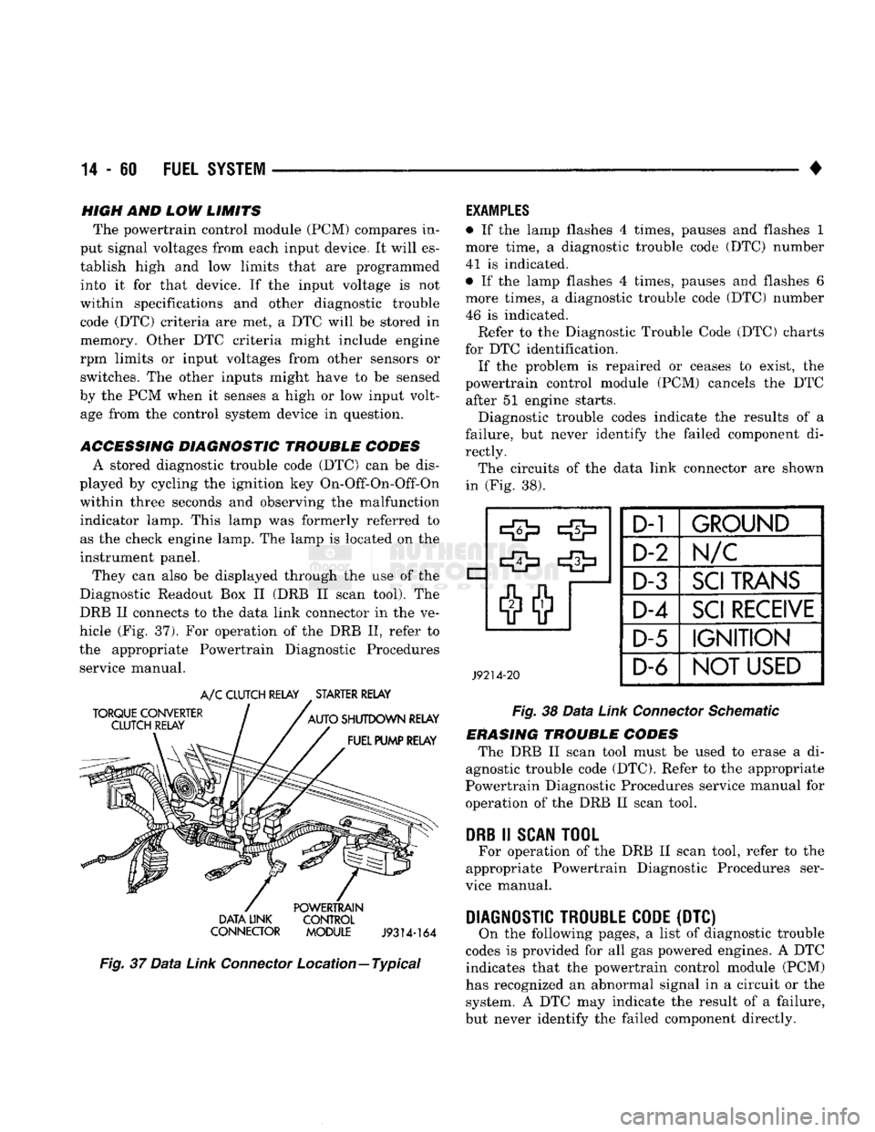
hicle (Fig. 37). For operation of the DRB II, refer to
the appropriate Powertrain Diagnostic Procedures service manual.
TORQUE CONVERTER
CLUTCH RELAY
A/C
CLUTCH RELAY
.
STARTER RELAY
AUTO
SHUTDOWN RELAY FUEL PUMP RELAY POWERTRAIN
DATA LINK CONTROL
CONNECTOR MODULE
J9314-164
Fig.
37
Data
Link
Connector
Location—Typical
EXAMPLES
• If the lamp flashes 4 times, pauses and flashes 1
more time, a diagnostic trouble code (DTC) number
41 is indicated.
• If the lamp flashes 4 times, pauses and flashes 6
more times, a diagnostic trouble code (DTC) number
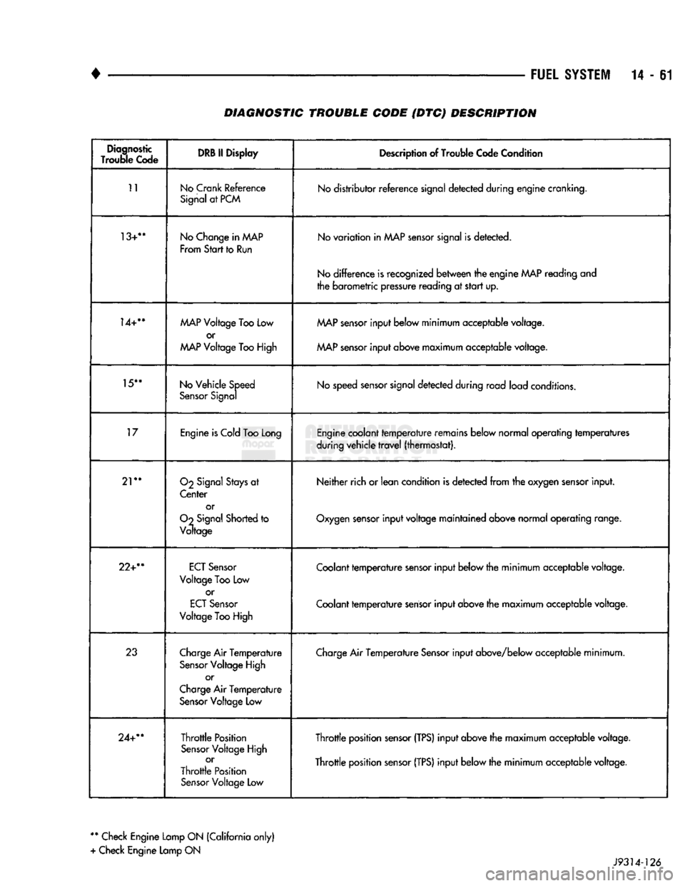
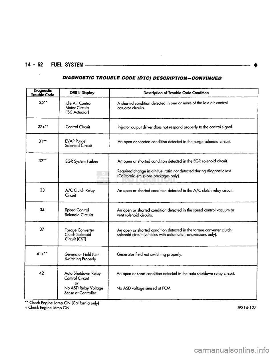
46 is indicated. Refer to the Diagnostic Trouble Code (DTC) charts
for DTC identification. If the problem is repaired or ceases to exist, the
powertrain control module (PCM) cancels the DTC after 51 engine starts.
Diagnostic trouble codes indicate the results of a
failure, but never identify the failed component di
rectly. The circuits of the data link connector are shown
in (Fig. 38).
J9214-20
D-1
GROUND
D-2 Im/c
D-3
SCI
TRANS
D-4
SCI
RECEIVE
D-5
IGNITION
D-6
NOT
USED
Fig.
38
Data
Link
Connector
Schematic
ERASING TROUBLE CODES The DRB II scan tool must be used to erase a di
agnostic trouble code (DTC). Refer to the appropriate
Powertrain Diagnostic Procedures service manual for operation of the DRB II scan tool.
DRB
II
SCAN
TOOL
For operation of the DRB II scan tool, refer to the
appropriate Powertrain Diagnostic Procedures ser
vice manual.
DIAGNOSTIC TROUBLE CODE
(DTC) On the following pages, a list of diagnostic trouble
codes is provided for all gas powered engines. A DTC indicates that the powertrain control module (PCM)
has recognized an abnormal signal in a circuit or the system. A DTC may indicate the result of a failure,
but never identify the failed component directly.
Page 880 of 1502
•
FUEL
SYSTEM
14-61 DIAGNOSTIC TROUBLE CODE {DTC) DESCRIPTION
Diagnostic
Trouble
Code DRB II
Display
Description of Trouble Code Condition
11
No
Crank
Reference
Signal at PCM No distributor reference signal detected during engine cranking.
13+**
No Change in
AAAP
From
Start
to Run No variation in MAP sensor signal is detected.
No difference is recognized between the engine
MAP
reading and
the barometric pressure reading at start up.
14+**
MAP
Voltage Too Low
or
MAP
Voltage Too High
MAP
sensor input below minimum acceptable voltage.
MAP sensor input above maximum acceptable voltage.
15**
No Vehicle Speed
Sensor Signal No speed sensor signal detected during road load conditions.
17
Engine is Cold Too Long Engine coolant temperature remains below normal operating temperatures
during vehicle travel (thermostat).
21**
O2
Signal Stays at
Center or
Oo
Signal Shorted to
Voltage Neither rich or lean condition
is
detected from the oxygen sensor input.
Oxygen sensor input voltage maintained above normal operating range.
22+**
ECT
Sensor
Voltage
Too
Low or
ECT
Sensor
Voltage
Too
High Coolant temperature sensor input below the minimum acceptable voltage.
Coolant temperature sensor input above the maximum acceptable voltage.
23
Charge Air Temperature
Sensor Voltage High or
Charge Air Temperature Sensor Voltage Low Charge Air Temperature Sensor input above/below acceptable minimum.
24+**
Throttle Position
Sensor Voltage High or
Throttle Position Sensor Voltage
Low
Throttle position sensor
(TPS)
input above the maximum acceptable voltage.
Throttle position sensor
(TPS)
input below the minimum acceptable voltage.
**
Check Engine Lamp ON (California only)
+ Check Engine Lamp ON J9314-126
Page 881 of 1502
14-62 FUEL
SYSTEM
• DIAGNOSTIC TROUBLE CODE (DTC) DESCRIPTION-CONTINUED
Diagnostic
Trouble Code
DRB
If Display
Description of Trouble Code Condition
25**
Idle Air Control
Motor Circuits
(ISC
Actuator) A shorted condition detected in one or more of the idle air control
actuator circuits.
27+**
Control
Circuit
Injector output driver does not
respond
properly to the control
signal.
31**
EVAP
Purge
Solenoid Circuit An open or shorted condition detected in the purge solenoid circuit.
32**
EGR System Failure An open or shorted condition detected in the EGR solenoid circuit.
Required change in air-fuel ratio not detected during diagnostic test
(California emissions packages only).
33 A/C Clutch Relay
Circuit An open or shorted condition detected in the A/C clutch relay circuit.
34 Speed Control
Solenoid Circuits An open or shorted condition detected in the speed control vacuum or
vent solenoid circuits.
37 Torque Converter
Clutch Solenoid Circuit
(CKT)
An open or shorted condition detected in the torque converter clutch
solenoid circuit (vehicles with automatic transmissions only).
41+** Generator Field Not
Switching Properly Generator field not switching properly.
42 Auto Shutdown Relay
Control Circuit
or
No
ASD
Relay Voltage
Sense at Controller An open or short condition detected in the auto shutdown relay circuit.
No
ASD
voltage sensed at PCM.
**
Check Engine Lamp ON (California only)
+ Check Engine Lamp ON J9314-127
Page 882 of 1502
•
FUEL
SYSTEM
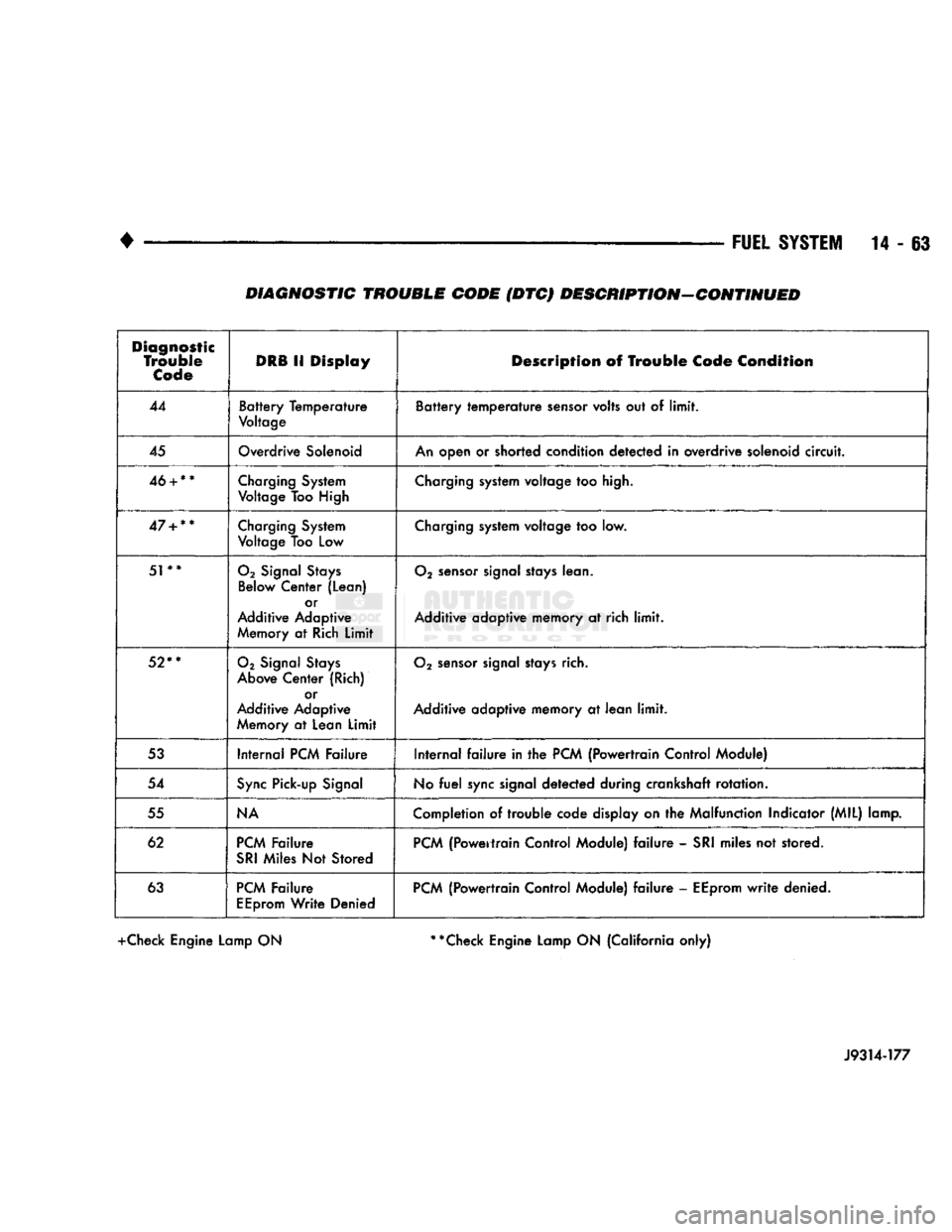
14 - 63 DIAGNOSTIC TROUBLE CODE (DTC) DESCRIPTION-CONTINUED
Diagnostic
Trouble
Code
DRB
11
Display
Description
of
Trouble
Code
Condition
44
Battery Temperature
Voltage
Battery temperature
sensor
volts
out of
limit.
45
Overdrive
Solenoid
An
open
or
shorted condition detected
in
overdrive solenoid
circuit.
46
+
**
Charging
System
Voltage
Too High
Charging
system voltage
too
high.
47
+
**
Charging
System
Voltage
Too
Low
Charging
system voltage
too low.
51**
02
Signal
Stays
Below
Center (Lean) or
Additive Adaptive
Memory
at
Rich
Limit
02
sensor
signal
stays
lean.
Additive adaptive memory
at rich
limit.
52**
02
Signal
Stays
Above
Center (Rich) or
Additive Adaptive
Memory
at
Lean
Limit
02
sensor
signal
stays
rich.
Additive adaptive memory
at
lean
limit.
53
Internal
PCM
Failure Internal
failure in the
PCM
{Powertrain Control Module)
54
Sync
Pick-up
Signal
No
fuel
sync
signal detected during crankshaft rotation.
55
NA
Completion
of trouble
code display
on the
Malfunction Indicator (MIL) lamp.
62
PCM
Failure
SRI
Miles
Not
Stored
PCM
(Powertrain Control Module)
failure -
SRI
miles
not
stored.
63
PCM
Failure
EEprom
Write Denied
PCM
(Powertrain Control Module)
failure -
EEprom
write
denied.
+Check Engine Lamp ON **Check Engine Lamp ON (California only)
J9314-177
Page 901 of 1502
14 - 82
FUEL 'SYSTEM
—. — ~—— — «
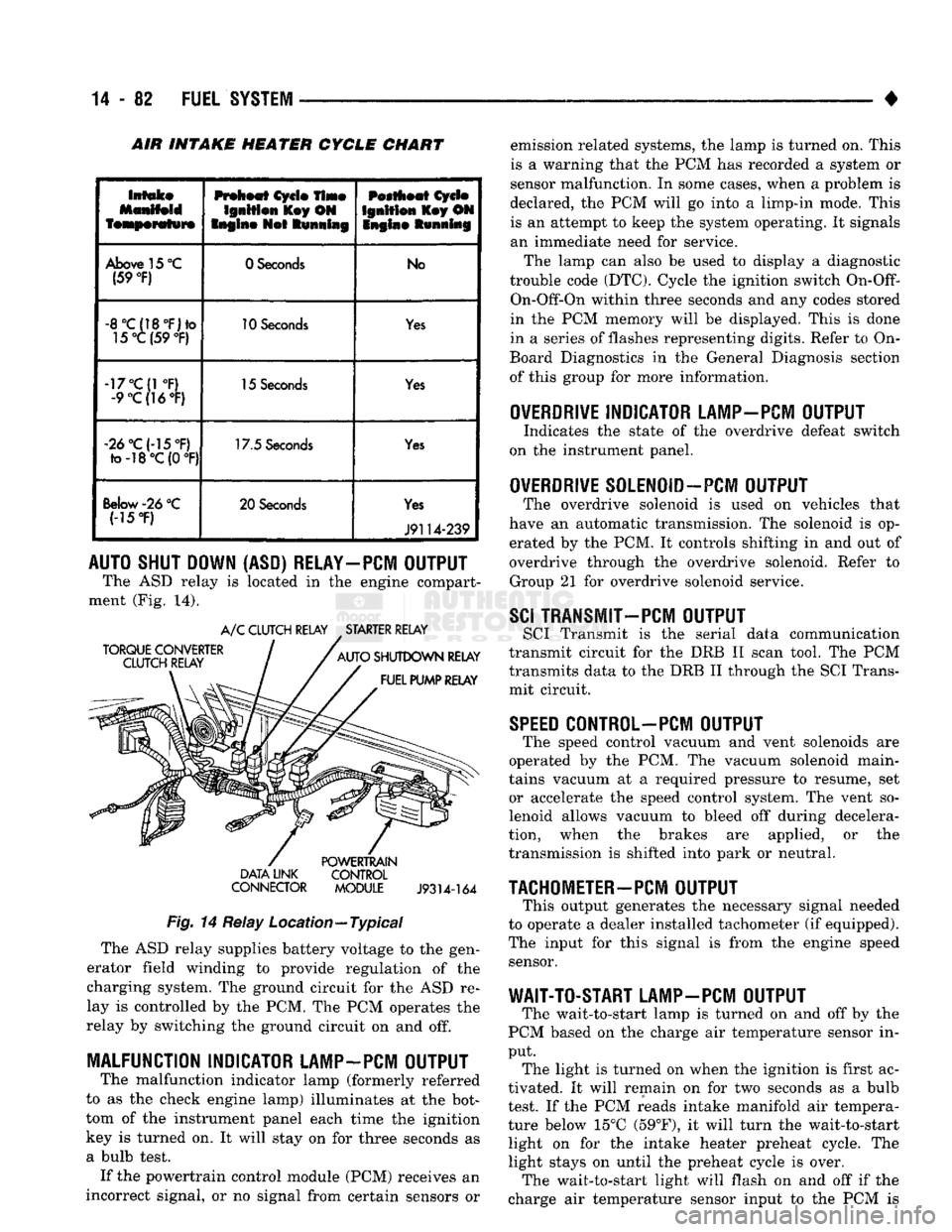
INTAKE HEATER CYCLE CHART
Intake
featperafwre
Preheat
Cycle
Time
Ignition
l£ey ON
Engine
Not
Running
Pestheat
Cycle
Ignition
Key ON
Snglne Running
Above
15
°C
(59
°F)
0 Seconds
No
-8°C(18°F)to
15°C (59
°F)
10
Seconds
Yes
-17°C(1
°F)
-9
°C(]6°F)
15
Seconds
Yes
«2d°C(-15°F)
to-18°C(0
°F) 17.5
Seconds
Yes
Below-26
°C (-15
*F)
20 Seconds
Yes
J9114-239
AUTO SHUT DOWN (ASD) RELAY-PCM OUTPUT
The ASD relay is located in the engine compart
ment (Fig. 14).
TORQUE CONVERTER
CLUTCH RELAY A/C CLUTCH RELAY STARTER RELAY
AUTO SHUTDOWN RELAY FUEL PUMP RELAY DATA LINK
CONNECTOR
POWERTRAIN
CONTROL MODULE
J9314-164
Fig.
14 Relay Location—Typical The ASD relay supplies battery voltage to the gen
erator field winding to provide regulation of the
charging system. The ground circuit for the ASD re
lay is controlled by the PCM. The PCM operates the
relay by switching the ground circuit on and off.
MALFUNCTION INDICATOR LAMP-PCM OUTPUT
The malfunction indicator lamp (formerly referred
to as the check engine lamp) illuminates at the bot
tom of the instrument panel each time the ignition
key is turned on. It will stay on for three seconds as
a bulb test. If the powertrain control module (PCM) receives an
incorrect signal, or no signal from certain sensors or emission related systems, the lamp is turned on. This
is a warning that the PCM has recorded a system or
sensor malfunction. In some cases, when a problem is
declared, the PCM will go into a limp-in mode. This is an attempt to keep the system operating. It signals
an immediate need for service.
The lamp can also be used to display a diagnostic
trouble code (DTC). Cycle the ignition switch
On-Off-
On-Off-On within three seconds and any codes stored
in the PCM memory will be displayed. This is done
in a series of flashes representing digits. Refer to On-
Board Diagnostics in the General Diagnosis section
of this group for more information.
OVERDRIVE
INDICATOR LAMP-PCM OUTPUT
Indicates the state of the overdrive defeat switch
on the instrument panel.
OVERDRIVE
S0LEN0ID-PCM OUTPUT
The overdrive solenoid is used on vehicles that
have an automatic transmission. The solenoid is op erated by the PCM. It controls shifting in and out of
overdrive through the overdrive solenoid. Refer to Group 21 for overdrive solenoid service.
SCI
TRANSMIT—PCM OUTPUT
SCI Transmit is the serial data communication
transmit circuit for the DRB II scan tool. The PCM
transmits data to the DRB II through the SCI Trans
mit circuit.
SPEED
C0NTR0L-PCM OUTPUT
The speed control vacuum and vent solenoids are
operated by the PCM. The vacuum solenoid main
tains vacuum at a required pressure to resume, set or accelerate the speed control system. The vent so
lenoid allows vacuum to bleed off during decelera
tion, when the brakes are applied, or the
transmission is shifted into park or neutral.
TACHOMETER-PCM
OUTPUT
This output generates the necessary signal needed
to operate a dealer installed tachometer (if equipped).
The input for this signal is from the engine speed sensor.
WAIT-TO-START LAMP-PCM OUTPUT
The wait-to-start lamp is turned on and off by the
PCM based on the charge air temperature sensor in
put. The light is turned on when the ignition is first ac
tivated. It will remain on for two seconds as a bulb
test. If the PCM reads intake manifold air tempera
ture below 15°C (59°F), it will turn the wait-to-start light on for the intake heater preheat cycle. The
light stays on until the preheat cycle is over. The wait-to-start light will flash on and off if the
charge air temperature sensor input to the PCM is
Page 913 of 1502
14
- 94
FUEL
SYSTEM
•
THROTTLE POSITION
SENSOR
TEST
CAUTION;
Before checking
the
TPS,
the
throttle
linkage must
be
checked
for
correct
adjustment.
The
throttle
lever must
contact
the low idle
speed screw.
The
throttle
lever must reach breakover when
the
throttle
is
wide
open. Refer
to the
Accelerator Pedal and
Throttle
Cable section
of
Group
14,
Fuel Systems.
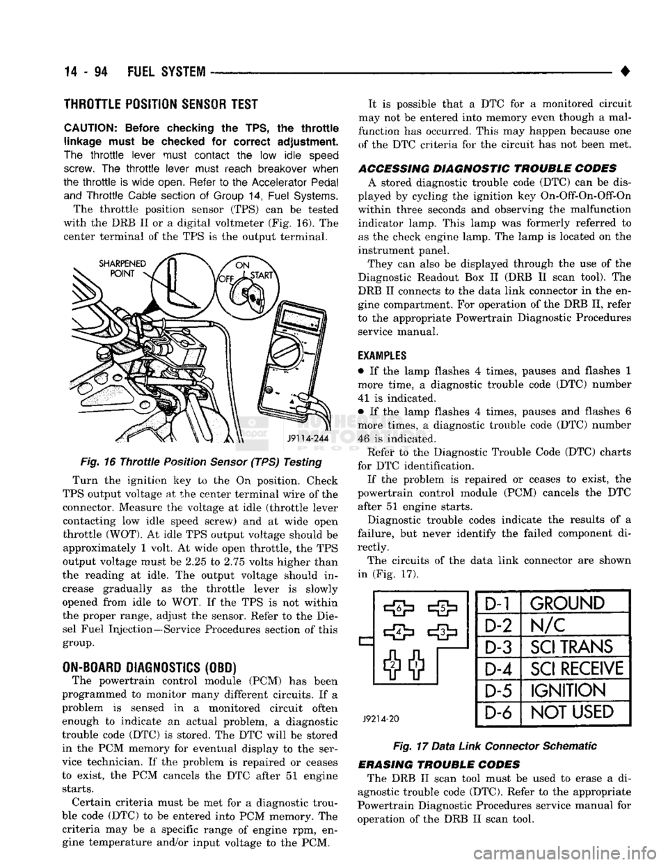
The throttle position sensor (TPS) can be tested
with the DRB II or a digital voltmeter (Fig. 16). The center terminal of the TPS is the output terminal.
J9114-244
Fig.
16
Throttle
Position
Sensor
(TPS) Testing
Turn the ignition key to the On position. Check
TPS output voltage at the center terminal wire of the connector. Measure the voltage at idle (throttle lever contacting low idle speed screw) and at wide open
throttle
(WOT).
At idle TPS output voltage should be approximately 1 volt. At wide open throttle, the TPS
output voltage must be 2.25 to 2.75 volts higher than
the reading at idle. The output voltage should in
crease gradually as the throttle lever is slowly
opened from idle to WOT. If the TPS is not within
the proper range, adjust the sensor. Refer to the Die sel Fuel Injection—Service Procedures section of this
group.
ON-BOARD
DIAGNOSTICS
(OBD) The powertrain control module (PCM) has been
programmed to monitor many different circuits. If a
problem is sensed in a monitored circuit often enough to indicate an actual problem, a diagnostic
trouble code (DTC) is stored. The DTC will be stored in the PCM memory for eventual display to the ser
vice technician. If the problem is repaired or ceases
to exist, the PCM cancels the DTC after 51 engine
starts.
Certain criteria must be met for a diagnostic trou
ble code (DTC) to be entered into PCM memory. The criteria may be a specific range of engine rpm, engine temperature and/or input voltage to the PCM. It is possible that a DTC for a monitored circuit
may not be entered into memory even though a mal
function has occurred. This may happen because one of the DTC criteria for the circuit has not been met.
ACCESSING DIAGNOSTIC TROUBLE CODES A stored diagnostic trouble code (DTC) can be dis
played by cycling the ignition key On-Off-On-Off-On
within three seconds and observing the malfunction indicator lamp. This lamp was formerly referred to
as the check engine lamp. The lamp is located on the
instrument panel.
They can also be displayed through the use of the
Diagnostic Readout Box II (DRB II scan tool). The
DRB II connects to the data link connector in the en
gine compartment. For operation of the DRB II, refer
to the appropriate Powertrain Diagnostic Procedures service manual.
EXAMPLES
• If the lamp flashes 4 times, pauses and flashes 1
more time, a diagnostic trouble code (DTC) number
41 is indicated.
• If the lamp flashes 4 times, pauses and flashes 6
more times, a diagnostic trouble code (DTC) number 46 is indicated. Refet* to the Diagnostic Trouble Code (DTC) charts
for DTC identification. If the problem is repaired or ceases to exist, the
powertrain control module (PCM) cancels the DTC after 51 engine starts.
Diagnostic trouble codes indicate the results of a
failure, but never identify the failed component di
rectly.
The circuits of the data link connector are shown
in (Fig. 17).
J9214-20
D-1
1
GROUND
D-2
N/C
D-3
SCI
TRANS
D-4
SCI
RECEIVE
D-5 IGNITION
D-6
NOT USED
Fig.
17
Data
Link
Connector
Schematic
ERASING TROUBLE CODES The DRB II scan tool must be used to erase a di
agnostic trouble code (DTC). Refer to the appropriate
Powertrain Diagnostic Procedures service manual for
operation of the DRB II scan tool.
Page 915 of 1502
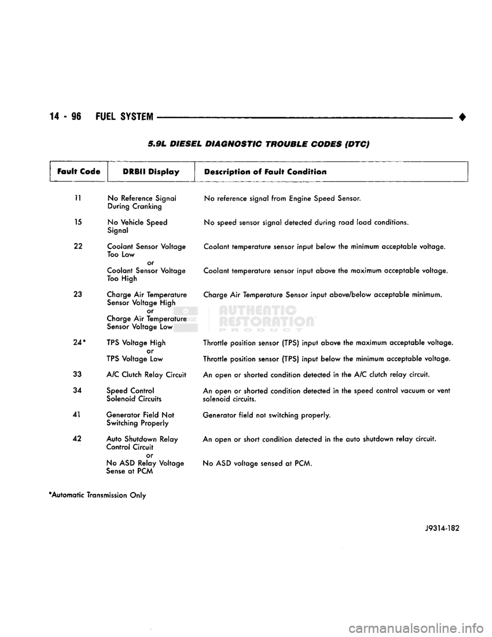
5.9L DIESEL DIAGNOSTIC TROUBLE CODES (DTC)
Fault
Code
DRBII
Display
Description
of Fault
Condition
11 No Reference Signal During Cranking
15 No Vehicle Speed Signal
22 Coolant Sensor Voltage Too Low or
Coolant Sensor Voltage
Too High
23 Charge Air Temperature Sensor Voltage High or
Charge Air Temperature Sensor Voltage Low
24*
TPS Voltage High or
TPS Voltage Low
33 A/C Clutch Relay Circuit
34 Speed Control Solenoid Circuits
41 Generator Field Not Switching Properly
42 Auto Shutdown Relay Control Circuit
or
No ASD Relay Voltage
Sense at PCM No reference signal from Engine Speed Sensor.
No speed sensor signal detected during road load conditions.
Coolant temperature sensor input below the minimum acceptable voltage.
Coolant temperature sensor input above the maximum acceptable voltage.
Charge Air Temperature Sensor input above/below acceptable minimum.
Throttle position sensor (TPS) input above the maximum acceptable voltage.
Throttle position sensor (TPS) input below the minimum acceptable voltage.
An open or shorted condition detected in the A/C clutch relay circuit.
An open or shorted condition detected in the speed control vacuum or vent solenoid circuits.
Generator field not switching properly.
An open or short condition detected in the auto shutdown relay circuit. No ASD voltage sensed at PCM.
*Automatic Transmission Only
J9314-182