1993 DODGE TRUCK instrument panel
[x] Cancel search: instrument panelPage 429 of 1502
8J
- 2
TURN SIGNALS AND HAZARD WARNING FLASHER
•
FUSE
BLOCK
INSTRUMENT
PANEL
REAR
VIEW
HAZARD
WARNING
FLASHER
VIEW
IN DIRECTION OF
ARROW
RR8JC10
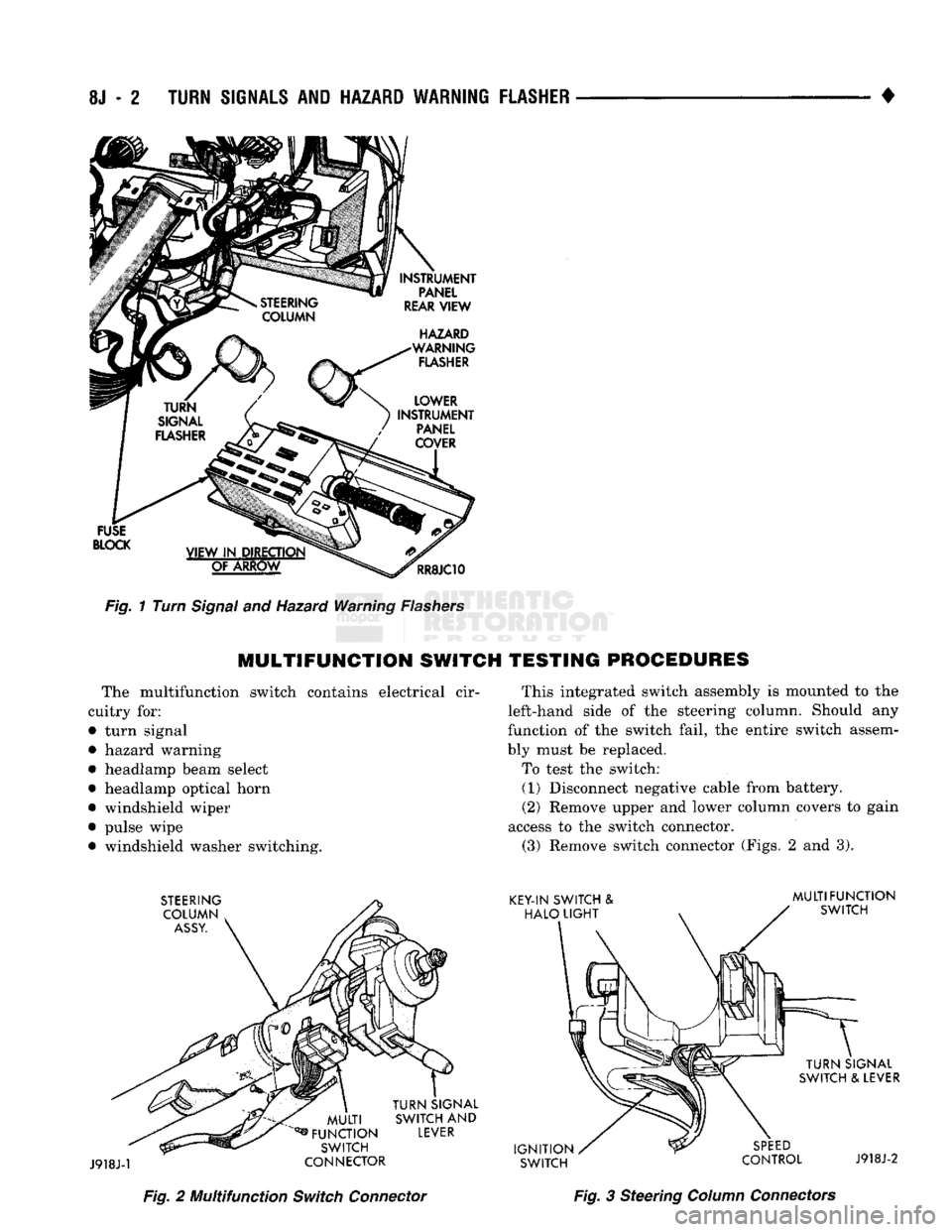
Fig.
1 Turn
Signal
and Hazard Warning
Flashers
MULTIFUNCTION
SWITCH TESTING PROCEDURES
The multifunction switch contains electrical cir
cuitry for:
• turn signal
• hazard warning
• headlamp beam select
• headlamp optical horn
• windshield wiper
• pulse wipe • windshield washer switching. This integrated switch assembly is mounted to the
left-hand side of the steering column. Should any
function of the switch fail, the entire switch assem
bly must be replaced.
To test the switch: (1) Disconnect negative cable from battery.
(2) Remove upper and lower column covers to gain
access to the switch connector. (3) Remove switch connector (Figs. 2 and 3).
Fig.
2 Multifunction
Switch
Connector
Fig.
3 Steering
Column
Connectors
Page 437 of 1502
8K
- 6
WINDSHIELD WIPER
AND
WASHER SYSTEMS
• INTERMITTENT WINDSHIELD WIPER FUNCTION
AND
SWITCH TESTING
PROCEDURES
INTERMITTENT
WIPER
FUNCTION
TESTING
PROCEDURES
The intermittent wipe and standard two speed mo
tors are identical. Refer to previous sections for diag
nosis of system problems which do not involve the
DELAY function. If problem occurs only in the DE LAY mode, the following tests are to be performed.
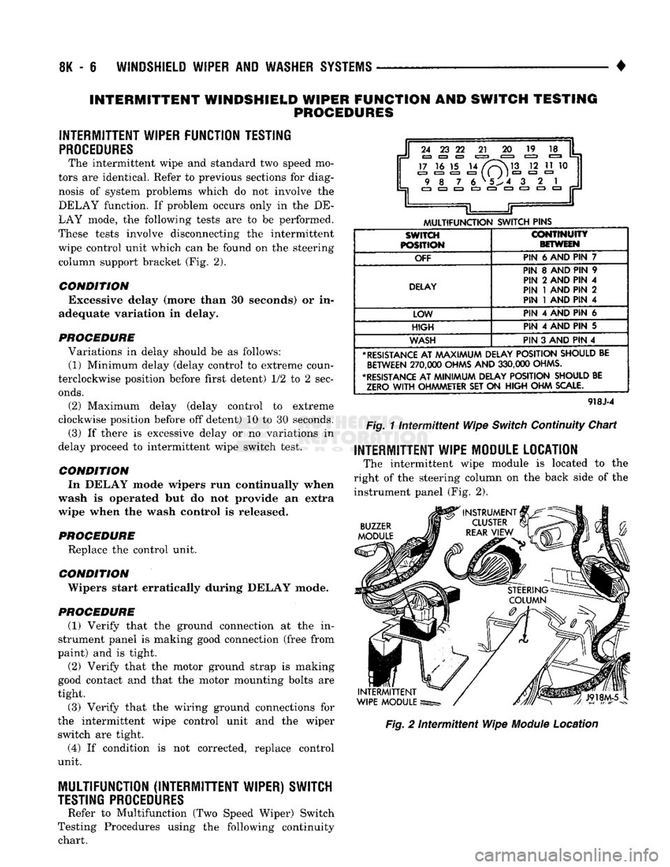
These tests involve disconnecting the intermittent wipe control unit which can be found on the steering column support bracket (Fig. 2).
CONDITION Excessive delay (more than 30 seconds) or in
adequate variation in delay.
PROCEDURE Variations in delay should be as follows: (1) Minimum delay (delay control to extreme coun
terclockwise position before first detent) 1/2 to 2 sec
onds.
(2) Maximum delay (delay control to extreme
clockwise position before off detent) 10 to 30 seconds.
(3) If there is excessive delay or no variations in
delay proceed to intermittent wipe switch test.
CONDITION In DELAY mode wipers run continually when
wash is operated but do not provide an extra
wipe when the wash control is released.
PROCEDURE Replace the control unit.
CONDITION ' Wipers start erratically during DELAY mode.
PROCEDURE (1) Verify that the ground connection at the in
strument panel is making good connection (free from
paint) and is tight.
(2) Verify that the motor ground strap is making
good contact and that the motor mounting bolts are
tight.
(3) Verify that the wiring ground connections for
the intermittent wipe control unit and the wiper switch are tight.
(4) If condition is not corrected, replace control
unit.
MULTIFUNCTION (INTERMITTENT WIPER) SWITCH
TESTING
PROCEDURES
Refer to Multifunction (Two Speed Wiper) Switch
Testing Procedures using the following continuity chart.
i
24 23 22
21 20 19
17 16 15 14
/V~\M3
12 11 10 9 8
7
6 V5^4 3
.
2 1
EZJ
CZ3 CZ3 C3 Jr
L
JT
MULTIFUNCTION
SWITCH
PINS
SWITCH
POSITION
CONTINUITY
BETWEEN
OFF
PIN
6 AND PIN 7
DELAY
PIN 8 AND PIN 9
PIN 2 AND PIN 4
PIN
1
AND PIN 2
PIN
1
AND PIN 4
LOW PIN 4 AND PIN 6
HIGH
PIN 4 AND PIN 5
WASH
PIN 3 AND PIN 4
*
RESISTANCE
AT
AAAXIMUM
DELAY
POSITION
SHOULD
BE
BETWEEN
270,000
OHMS
AND
330,000
OHMS.
•RESISTANCE
AT
MINIMUM
DELAY
POSITION
SHOULD
BE
ZERO
WITH
OHMMETER
SET ON
HIGH
OHM
SCALE.
918J-4
Fig.
11ntermittent
Wipe
Switch
Continuity Chart
INTERMITTENT WIPE MODULE LOCATION
The intermittent wipe module is located to the
right of the steering column on the back side of the instrument panel (Fig. 2).
BUZZER
MODULE
INTERMITTENT
WIPE
MODULE
Fig.
2
Intermittent
Wipe
Module
Location
Page 447 of 1502
8L
- 4
LAMPS
• (3) Up 1.27 meters (5 feet) from the floor, tape a
line on the wall at the centerline of the vehicle.
Sight along the centerline of the vehicle (from rear of
vehicle forward) to verify accuracy of the line place
ment.
(4) Rock vehicle side-to-side three times to allow
suspension to stabilize. (5) Jounce front suspension three times by pushing
downward on front bumper and releasing. (6) Measure the distance from the center of head
lamp lens to the floor. Transfer measurement to the alignment screen (with tape). Use this line for up/
down adjustment reference.
(7) Measure distance from the centerline of the ve
hicle to the center of each headlamp being aligned. Transfer measurements to screen (with tape) to each side of vehicle centerline. Use these lines for left/
right adjustment reference.
HEADLAMP
ADJUSTMENT
A properly aimed low beam headlamp will project
top edge of high intensity pattern on screen from 50 mm (2 in.) above to 50 mm (2 in.) below headlamp
centerline. The side-to-side outboard edge of high in
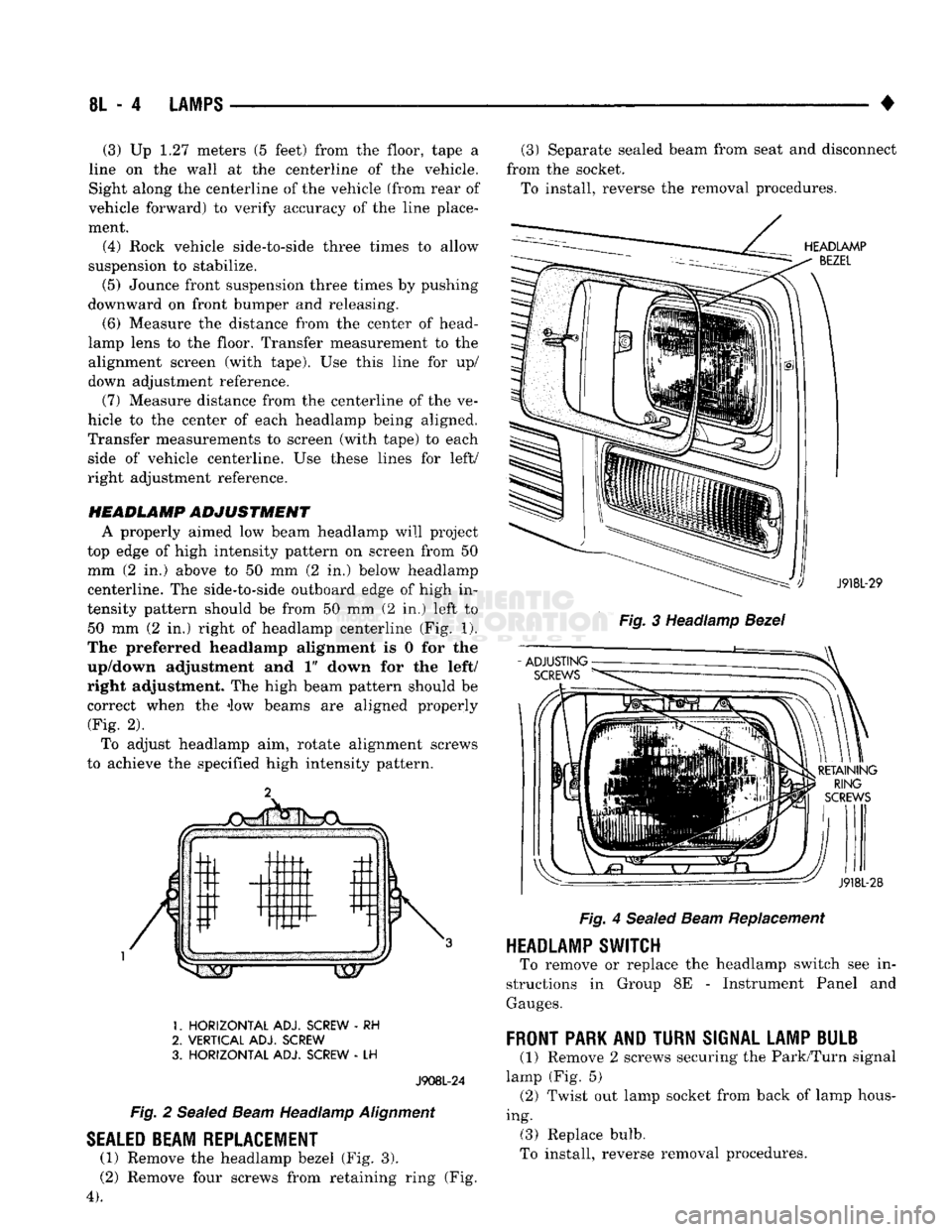
tensity pattern should be from 50 mm (2 in.) left to 50 mm (2 in.) right of headlamp centerline (Fig. 1).
The preferred headlamp alignment is 0 for the
up/down adjustment and 1" down for the left/
right adjustment. The high beam pattern should be correct when the iow beams are aligned properly (Fig. 2).
To adjust headlamp aim, rotate alignment screws
to achieve the specified high intensity pattern.
1.
HORIZONTAL
ADJ. SCREW
- RH
2.
VERTICAL
ADJ. SCREW
3.
HORIZONTAL
ADJ. SCREW
- LH
J908L-24
Fig.
2
Sealed
Beam
Headlamp
Alignment
SEALED
BEAM REPLACEMENT
(1) Remove the headlamp bezel (Fig. 3).
(2) Remove four screws from retaining ring (Fig.
4).
(3) Separate sealed beam from seat and disconnect
from the socket. To install, reverse the removal procedures.
HEADLAMP
BEZEL
: ') J918L-29
Fig.
3 Headlamp
Bezel
RETAINING
RING
SCREWS
J918L-28
Fig.
4
Sealed
Beam
Replacement
HEADLAMP SWITCH
To remove or replace the headlamp switch see in
structions in Group 8E - Instrument Panel and
Gauges.
FRONT
PARK AND
TURN
SIGNAL LAMP BULB
(1) Remove 2 screws securing the Park/Turn signal
lamp (Fig. 5) (2) Twist out lamp socket from back of lamp hous
ing. (3) Replace bulb.
To install, reverse removal procedures.
Page 454 of 1502
•
LAMPS
8L - 11
BULB
APPLICATION
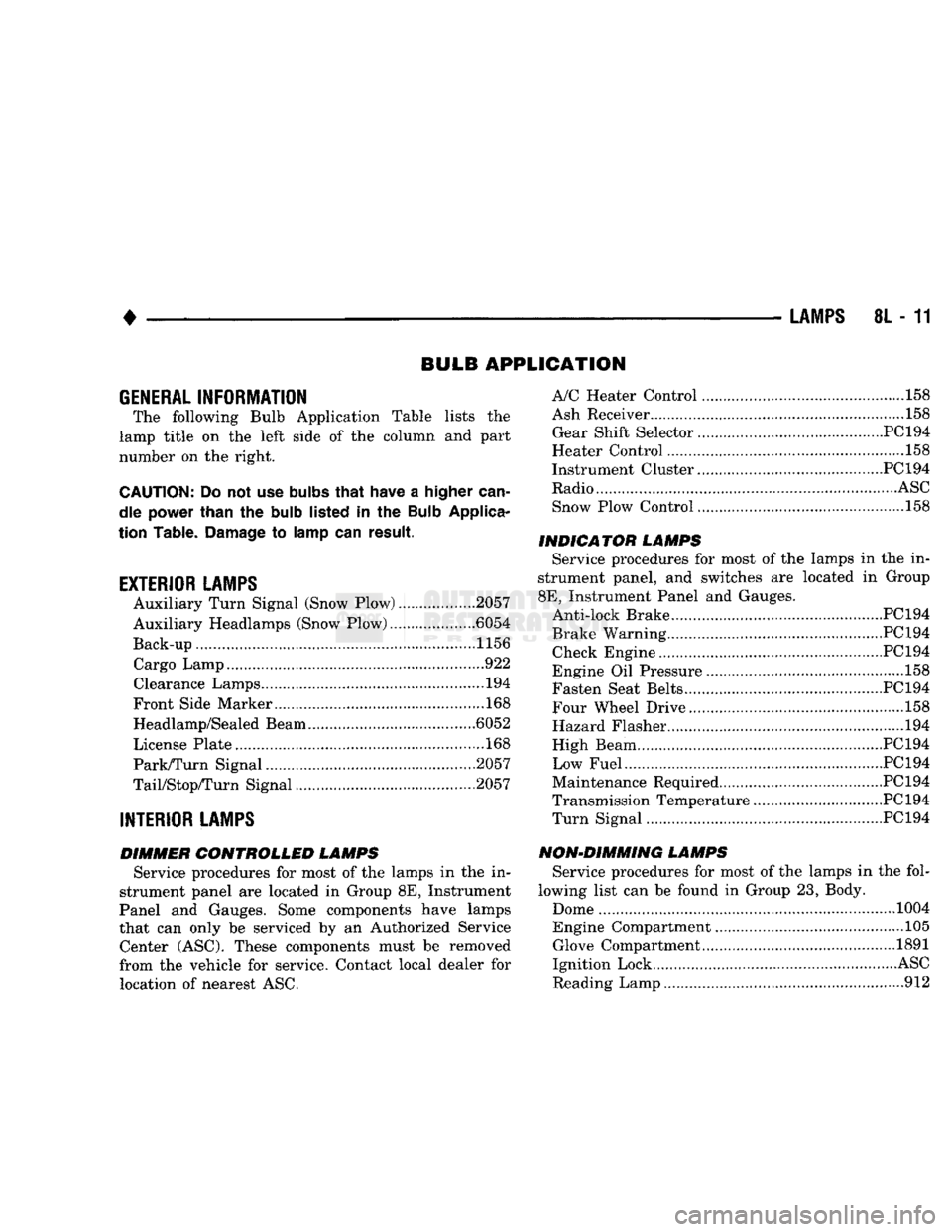
GENERAL
INFORMATION
The following Bulb Application Table lists
the
lamp title
on the
left side
of the
column
and
part
number
on the
right.
CAUTION:
Do not use
bulbs
that
have
a
higher
can
dle power than
the
bulb
listed
in the
Bulb
Applica
tion Table.
Damage
to
lamp
can
result.
EXTERIOR LAMPS
Auxiliary Turn Signal (Snow Plow) 2057
Auxiliary Headlamps (Snow Plow) .6054
Back-up....................... .......1156 Cargo Lamp..
922
Clearance Lamps
194
Front Side Marker
168
Headlamp/Sealed Beam .6052
License Plate
168
Park/Turn Signal 2057
TaiyStop/Turn Signal ...2057
INTERIOR LAMPS
DIMMER CONTROLLED LAMPS Service procedures
for
most
of the
lamps
in the in
strument panel
are
located
in
Group
8E,
Instrument
Panel
and
Gauges. Some components have lamps
that
can
only
be
serviced
by an
Authorized Service Center (ASC). These components must
be
removed
from
the
vehicle
for
service. Contact local dealer
for
location
of
nearest
ASC.
A/C Heater Control
158
Ash Receiver
..158
Gear Shift Selector...........................................PC194
Heater Control
158
Instrument Cluster.. PC 194
Radio
ASC
Snow Plow Control
.158
INDICATOR LAMPS Service procedures
for
most
of the
lamps
in the in
strument panel,
and
switches
are
located
in
Group
8E,
Instrument Panel
and
Gauges. Anti-lock Brake PC194
Brake Warning PC194 Check Engine PC194
Engine
Oil
Pressure
158
Fasten Seat Belts.. PC 194 Four Wheel Drive ....158
Hazard Flasher
194
High Beam PC194
Low Fuel....... JPC194
Maintenance Required PC 194
Transmission Temperature ..PC 194 Turn Signal PC194
NON-DIMMING LAMPS Service procedures
for
most
of the
lamps
in the
fol
lowing list
can be
found
in
Group
23,
Body.
Dome
1004
Engine Compartment ...105 Glove Compartment....
1891
Ignition Lock
ASC
Reading Lamp
912
Page 456 of 1502
•
REAR
WINDOW DEFOGGER
8N - 1
REAR
WINDOW
DEFOGGER
CONTENTS
page
REPAIR
PROCEDURES (GRID LINES,
TERMINALS,
AND
PIGTAILS)
3
GENERAL
INFORMATION
The electrically heated rear window defogger
is
available
on
Ramcharger with sunscreen glass only. The system consists
of a
rear window with
two
ver
tical
bus
bars
and a
series
of
electrically connected
grid lines baked
on the
inside surface. Circuit protection
for the
heated grid circuit
is
pro
vided
by a 18
gauge fusible link wire located
in the
engine compartment.
The
relay circuit
is
protected
by
a 20 amp
fuse, located
in the
fuse block. When
the
rear window defogger switch
is
placed
in
the
ON
position, current
is
directed
to
rear window
grid lines.
The
heated grid lines
in
turn heat
the
rear window
to
clear
the
surface
of fog or
snow.
CAUTION;
Grid lines
can be
damaged
or
scraped
off
with
sharp instruments. Care should
be
taken
in
page
SERVICE
PROCEDURES
4
TEST
PROCEDURES
1
cleaning
the
glass
or
removing foreign materials,
decals
or
stickers. Normal
glass
cleaning solvents
or
hot
water
used
with
rags
or
toweling
is
recom mended.
SYSTEM
DESCRIPTION CONTROL
SWITCH/TIMER
RELAY MODULE
The control switch
and
timer relay
are
integrated
into
a
single panel mounted assembly. Actuating
the
switch energizes
the
electronic timing circuit. This
allows current
to
flow through
the
grid system
for
approximately
10
minutes,
or
until either
the
control
switch
or
ignition
is
turned
off. An
indicating lamp
illuminates
a
lens inlaid
in the
control switch.
TEST PROCEDURES
SYSTEM
TEST
Electrically heated rear window defogger operation
can
be
checked in-vehicle
in the
following manner: (1) Turn
the
ignition
ON.
(2) Turn rear window defogger control switch
ON.
(3) Monitor vehicle voltmeter. With
the
control
switch
ON, a
distinct needle deflection should
be
noted. (4)
The
rear window defogger operation
can be
checked
by
feeling
the
glass.
A
distinct difference
in
temperature between
the
grid lines
and
adjacent clear glass
can be
detected
in 3 to 4
minutes
of
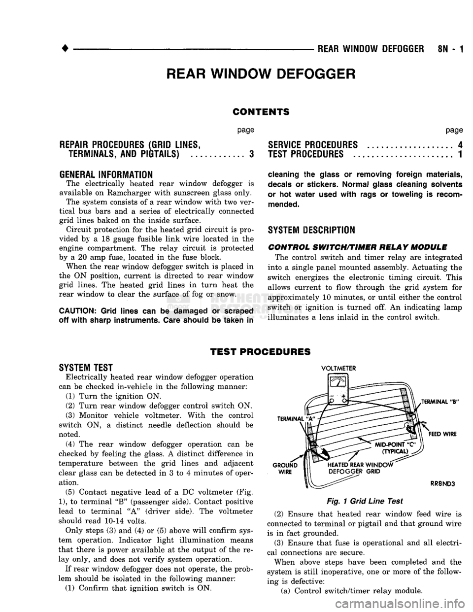
operation. (5) Contact negative lead
of a DC
voltmeter
(Fig.
1),
to
terminal
"B"
(passenger side). Contact positive
lead
to
terminal
"A"
(driver side).
The
voltmeter
should read
10-14
volts. Only steps
(3) and (4) or (5)
above will confirm sys
tem operation. Indicator light illumination means
that there
is
power available
at the
output
of the re
lay only,
and
does
not
verify system operation.
If rear window defogger does
not
operate,
the
prob
lem should
be
isolated
in the
following manner:
(1) Confirm that ignition switch
is ON.
VOLTMETER
Fig.
1
Grid
Line
Test (2) Ensure that heated rear window feed wire
is
connected
to
terminal
or
pigtail
and
that ground wire
is
in
fact grounded.
(3) Ensure that fuse
is
operational
and all
electri
cal connections
are
secure.
When above steps have been completed
and the
system
is
still inoperative,
one or
more
of the
follow
ing
is
defective:
(a) Control switch/timer relay module.
Page 457 of 1502
8N
- 2
REAR WINDOW DEFOGGER
• (b) Rear window grid lines (all grid lines would
have to be broken) or one of the feed wires are not
connected for the system to be inoperative.
The following paragraphs outline component check
out procedures.
If turning the switch ON produces severe voltmeter
deflection, the circuit should be closely checked for a shorting condition. If system operation has been verified but indicator
bulb does not light, check and replace bulb.
For detailed wiring information, refer to Group 8W
- Wiring Diagrams.
REAR
WINDOW GRID LINES TEST
Horizontal grid lines and vertical bus bar lines
printed and baked on inside surface of rear window glass (Fig. 1) comprise an electrical parallel circuit.
The electrically conductive lines are made of a silver- ceramic material. When baked onto glass they be
come bonded to the glass and are highly resistant to abrasion. It is possible, however, that a break may
exist or occur in an individual grid line resulting in
no current flow through the line. To detect breaks in
grid lines, the following procedure is required: (1) Turn ignition on and push control switch to
ON. Indicator light should come on. (2) Contact negative lead of a DC voltmeter, to
vertical bus bar connecting grid lines on passenger side of vehicle (point A of Fig. 1). Contact positive
lead of voltmeter, to vertical bus bar on driver side of
vehicle (point B of Fig. 1). Voltmeter should read 10-14 volts. (3) With negative lead of voltmeter, contact a good
body ground point. Voltage reading should not change. A different reading indicates a poor ground connection. (4) Connect negative lead of voltmeter to Point A
on passenger side bus bar and touch each grid line at
Mid-Point with positive lead. A reading of approxi mately 6 volts indicates a line is good. A reading of 0
volts indicates a break in line between Mid-Point C and Point B. A reading of 10-14 volts indicates a
break between Mid-Point C and ground Point A. Move toward break and voltage will change as soon as break is crossed.
CONTROL SWITCH/TIMER MODULE TEST
Control switch/timer relay module may be tested
in-vehicle or bench tested. In vehicle testing is ac
complished in the following manner: (1) Remove switch from instrument panel (refer to
Control Switch Replacement) and leave switch con
nector plugged in. (2) Turn ignition ON.
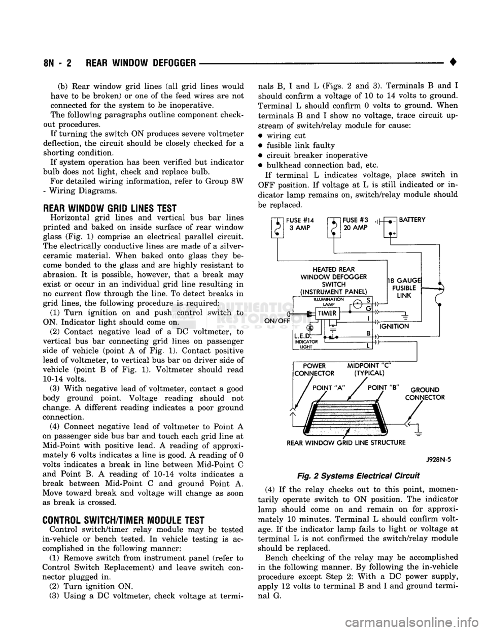
(3) Using a DC voltmeter, check voltage at termi nals B, I and L (Figs. 2 and 3). Terminals B and I
should confirm a voltage of 10 to 14 volts to ground.
Terminal L should confirm 0 volts to ground. When terminals B and I show no voltage, trace circuit up
stream of switch/relay module for cause:
• wiring cut
• fusible link faulty
• circuit breaker inoperative
• bulkhead connection bad, etc. If terminal L indicates voltage, place switch in
OFF position. If voltage at L is still indicated or in
dicator lamp remains on, switch/relay module should
be replaced.
"XI
FUSE
#14
rr~
P 3
AAAP
P
FUSE
#3
20
AAAP
BATTERY
HEATED
REAR
WINDOW
DEFOGGER
SWITCH
(INSTRUMENT
PANEL)
ON/OFF
ILLUMINATION
LAMP
fez TIMER
L.E.I
INDICATOR
LIGHT
-©-
18
GAUGE
FUSIBLE
LINK
IGNITION POWER
MIDPOINT
"C"
CONNECTOR (TYPICAL)
POINT
"A"
POINT
"B"
GROUND
CONNECTOR
REAR
WINDOW
GRID
LINE
STRUCTURE
Fig.
2
Systems
Electrical Circuit
J928N-5
(4) If the relay checks out to this point, momen
tarily operate switch to ON position. The indicator lamp should come on and remain on for approxi
mately 10 minutes. Terminal L should confirm volt
age.
If the indicator lamp fails to light or voltage at
terminal L is not confirmed the switch/relay module should be replaced.
Bench checking of the relay may be accomplished
in the following manner. By following the in-vehicle
procedure except Step 2: With a DC power supply, apply 12 volts to terminal B and I and ground termi
nal G.
Page 462 of 1502
•
POWER
WINDOWS
8S - 1
POWER WINDOWS
CONTENTS
page
SERVICE
PROCEDURES
3
GENERAL
INFORMATION
Power window motors are of the permanent mag
net type. A positive and negative battery connection
to either of the two motor terminals will cause the motor to rotate in one direction. Reversing current
through these same two connections will cause the motor to rotate in the opposite direction. Both motors are grounded through the master
switch by a black wire attached to a ground stud.
The stud is located on the back of the instrument
panel, on the right side of the steering column. It is necessary that the window be free to slide up
page
TEST
PROCEDURES
....................... 1
and down in the glass channels or tubes and tracks.
If the window is not free to move up and down, the
window motor will not be able to move the glass.
To determine if the glass is free, disconnect the
electric window regulator lift arm sliders from the
glass lift channels. Slide the window up and down by
hand.
A less positive method is to shake the glass in the
door, (with glass positioned between the up and down
stop positions). If the glass will move slightly from
side to side, front to rear, and up and down, the win
dow is probably not bound tight in the tracks.
TEST
PROCEDURES
SWITCH
VOLTAGE TEST
The following wiring test sequence determines
whether or not voltage is continuous through the
body harness to switch. (1) Remove power window/lock switch by inserting
a standard blade screwdriver into notch on forward
end of switch housing. Push screwdriver to depress
locking tab. Pull bezel out and forward to remove
from door panel. (2) Carefully separate multiple terminal block on
wiring harness from switch body. (3) Connect one lead of test light to black (BK)
wire terminal. Touch other test light lead to tan (TN)
wire terminal. If test light comes on, the wiring cir cuit between the battery and switch is functional. If
light does not come on, check 30 amp circuit breaker,
or for a broken wire or poor ground.
CIRCUIT
BREAKER
TEST
Locate the circuit breaker in fuse cavity number 12
on fuse block. Pull out slightly but be sure that cir
cuit breaker terminals still contact terminals in fuse
block. Connect ground wire of voltmeter to a good ground. With probe of voltmeter positive wire, check both terminals of circuit breaker for battery voltage.
If only one terminal checks at battery voltage, circuit
breaker is defective and must be replaced. If neither
terminal shows battery voltage, check for open or shorted circuit to circuit breaker.
SWITCH TEST
For switch testing, remove the switch from its
mounting location. Using an ohmmeter, refer to Figs. 1 and 2 to determine if continuity is correct in the
UP and DOWN switch positions. If continuity is cor
rect perform window lift motor test.
WINDOW
MOTOR TEST
(1) Connect positive lead (from a test battery) to
either of the two motor terminals. (2) Connect negative lead (from test battery) to re
maining motor terminal. (3) The motor should now rotate in one direction to
either move window up or down. (a) If window happens to already be in full UP
position and motor is connected to rotate in UP di rection, no movement will be observed.
Page 468 of 1502
POWER
MIRRORS
CONTENTS
page
SERVICE PROCEDURES
2
GENERAL
INFORMATION
Electrically-operated remote control mirrors are
available as an option on D-body vehicles. The mir
rors are controlled by a single switch assembly lo
cated on the instrument panel to the right of the
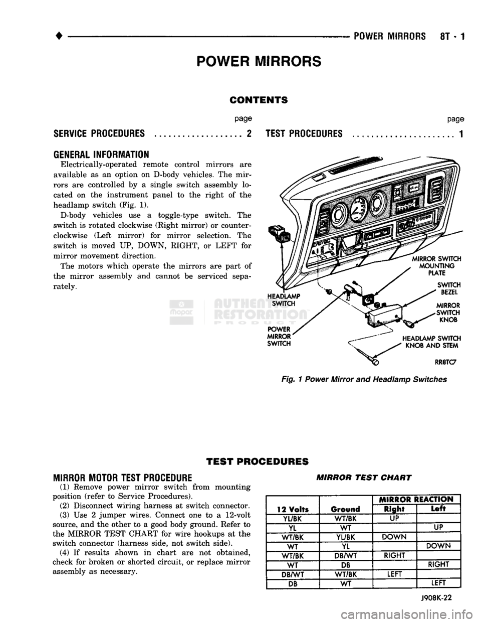
headlamp switch (Fig. 1). D-body vehicles use a toggle-type switch. The
switch is rotated clockwise (Right mirror) or counter
clockwise (Left mirror) for mirror selection. The
switch is moved UP, DOWN, RIGHT, or LEFT for
mirror movement direction. The motors which operate the mirrors are part of
the mirror assembly and cannot be serviced sepa
rately.
page
TEST PROCEDURES
...................... 1 Fig. 1 Power Mirror and Headlamp Switches
TEST
PROCEDURES
MIRROR MOTOR TEST PROCEDURE
(1) Remove power mirror switch from mounting
position (refer to Service Procedures). (2) Disconnect wiring harness at switch connector.
(3) Use 2 jumper wires. Connect one to a
12-volt
source, and the other to a good body ground. Refer to
the MIRROR TEST CHART for wire hookups at the switch connector (harness side, not switch side), (4) If results shown in chart are not obtained,
check for broken or shorted circuit, or replace mirror assembly as necessary. MIRROR
TEST
CHART
12 Volts Ground MIRROR REACTION
12 Volts Ground Right
Left
Yl/BK
1
WT/BK UP
YL WT UP
WT/BK
YL/BK
DOWN
WT YL DOWN
WT/BK DB/WT RIGHT
WT
DB
RIGHT
DB/WT WT/BK LEFT
DB
WT LEFT
J908K-22