1993 DODGE TRUCK service indicator
[x] Cancel search: service indicatorPage 607 of 1502

9
- 2
ENGINES
rial surrounds each mounting hole. Excess material
can easily be wiped off. Components should be
torqued in place within 15 minutes. The use of a lo cating dowel is recommended during assembly to pre
vent smearing the material off location.
ENGINE PERFORMANCE
To provide best vehicle performance and lowest ve
hicle emissions, it is most important that the tune-up
be done accurately. Use the specifications listed on
the Vehicle Emission Control Information label found on the engine compartment hood.
(1) Test cranking amperage draw (refer to Group
8B,
Battery/Starter/Generator Service for the proper
procedures).
(2) Tighten the intake manifold bolts (refer to
Group 11, Exhaust System and Intake Manifold for
the proper specifications). (3) Perform cylinder compression test:
(a) Check engine oil level and add oil, if neces
sary.
(b) Drive the vehicle until engine reaches normal
operating temperature. (c) Select a route free from traffic and other
forms of congestion, observe all traffic laws and
briskly accelerate through the gears several times. The higher engine speed may help clean out valve seat deposits which can prevent accurate compres
sion readings.
CAUTION:
DO NOT
overspeed
the
engine.
(d) Remove all spark plugs from engine. As
spark plugs are being removed, check electrodes for
abnormal firing indicators - fouled, hot, oily, etc.
Record cylinder number of spark plug for future
reference.
(e) Disconnect coil wire from distributor and se
cure to good ground to prevent a spark from start
ing a fire.
(f) Be sure throttle blades are fully open during
the compression check. (g) Insert compression gage adaptor into the
No.l spark plug hole. Crank engine until maxi
mum pressure is reached on gauge. Record this
pressure as No.l cylinder pressure.
(h) Repeat Step 3g for all remaining cylinders.
(i) Compression should not be less than 689 kPa
(100 psi) and not vary more than 172 kPa (25 psi)
from cylinder to cylinder.
(j) If cylinder(s) have abnormally low compres
sion pressures, repeat steps 3a through 3h. (k) If the same cylinder(s) repeat an abnormally
low reading, it could indicate the existence of a
problem in the cylinder.
The recommended compression pressures are
to be used only as a guide to diagnosing engine
problems. An engine should NOT be disassem bled to determine the cause of low compression
unless some malfunction is present. (4) Clean or replace spark plugs as necessary. Ad
just gap (refer to Group 8D, Ignition System for gap adjustment and torque).
(5) Test resistance of spark plug cables (refer to
Group 8D, Ignition System.
(6) Inspect the primary wire. Test coil output volt
age,
primary and secondary resistance. Replace parts as necessary (refer to Group 8D, Ignition System and
make necessary adjustment).
(7) Set ignition timing to specifications (refer to
Specification Label on engine compartment hood).
(8) Perform a combustion analysis.
(9) Test fuel pump for pressure and vacuum (refer
to Group 14, Fuel System for the proper specifica
tions).
(10) Inspect air filter element (refer to Group 0,
Lubrication and Maintenance for the proper proce
dure).
(11) Inspect crankcase ventilation system (refer to
Group 0, Lubrication and Maintenance for the proper
procedure).
(12) For emission controls refer to Group 25, Emis
sion Controls System for service procedures.
(13) Inspect and adjust accessory belt drives (refer
to Group 7, Cooling System for the proper adjust
ments).
(14) Road test vehicle as a final test.
H0NIN6
CYLINDER
BORES
Before honing, stuff plenty of clean shop towels un
der the bores and over the crankshaft to keep abra sive materials from entering the crankshaft area.
(1) Used carefully, the Cylinder Bore Sizing Hone
C-823 equipped with 220 grit stones, is the best tool
for this job. In addition to deglazing, it will reduce
taper and out-of-round as well as removing light scuffing, scoring or scratches. Usually a few strokes
will clean up a bore and maintain the required lim
its.
CAUTION:
DO NOT use rigid type
hones
to remove
cylinder
wall
glaze.
(2) Deglazing of the cylinder walls may be done if
the cylinder bore is straight and round. Use a cylin
der surfacing hone, Honing Tool C-3501, equipped
with 280 grit stones (C-3501-3810). 20-60 strokes, de
pending on the bore condition, will be sufficient to
provide a satisfactory surface. Using honing oil C-3501-3880 or a light honing oil available from ma
jor oil distributors.
CAUTION:
DO NOT use engine or
transmission
oil, mineral
spirits
or
kerosene.
Page 630 of 1502
•
3.9L
ENGINE
9 - 25
VALVES
/
VALVE
SPRINGS
The valves are arranged in-line and inclined 18°.
The rocker pivot support and the valve guides are cast integral with the heads. This procedure requires the removal of the cylinder
head.
REMOVAL
(1) Remove the cylinder head.
(2) Compress valve springs using Valve Spring
Compressor Tool MD-998772A.
(3) Remove valve retaining locks, valve spring re
tainers, valve stem seals and valve springs.
(4) Before removing valves, remove any burrs from
valve stem lock grooves to prevent damage to the
valve guides. Identify valves to ensure installation in
original location.
VALVE
CLEANING
Clean valves thoroughly. Discard burned, warped
and cracked valves.
Remove carbon and varnish deposits from inside of
valve guides with a reliable guide cleaner.
VALVE
INSPECTION
Measure valve stems for wear. If wear exceeds
0.051 mm (0.002 inch), replace the valve. Measure valve stem guide clearance as follows:
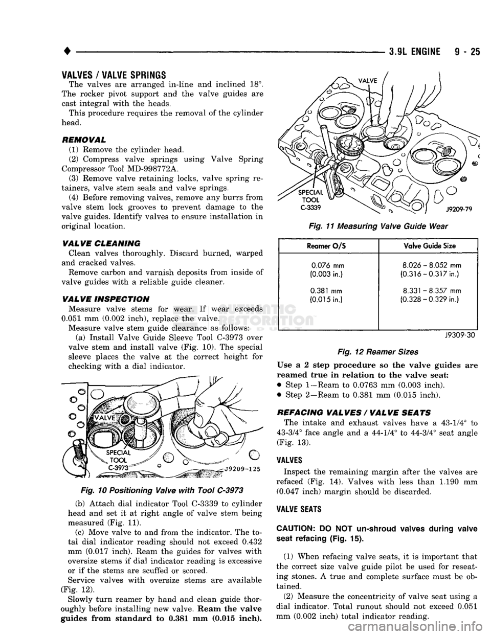
(a) Install Valve Guide Sleeve Tool C-3973 over
valve stem and install valve (Fig. 10). The special sleeve places the valve at the correct height for
checking with a dial indicator.
Fig.
10 Positioning Valve with Tool C-3973
(b) Attach dial indicator Tool C-3339 to cylinder
head and set it at right angle of valve stem being
measured (Fig. 11).
(c) Move valve to and from the indicator. The to
tal dial indicator reading should not exceed 0.432
mm (0.017 inch). Ream the guides for valves with
oversize stems if dial indicator reading is excessive
or if the stems are scuffed or scored.
Service valves with oversize stems are available
(Fig. 12).
Slowly turn reamer by hand and clean guide thor
oughly before installing new valve. Ream the valve
guides from standard to 0.381 mm (0,015 inch).
Fig.
11 Measuring Valve Guide Wear
Reamer
O/S
Valve
Guide
Size
0.076
mm
8.026
-
8.052
mm
(0.003 in.) (0.316 -0.317 in.)
0.381
mm 8.331 -8.357 mm
(0.015 in.)
(0.328-0.329
in.)
J9309-30
Fig.
12
Reamer
Sizes
Use a 2 step procedure so the valve guides are
reamed true in relation to the valve seat:
•
Step 1-Ream to 0.0763 mm (0.003 inch).
•
Step 2-Ream to 0.381 mm (0.015 inch).
REFACING
VALVES
/
VALVE
SEATS
The intake and exhaust valves have a 43-1/4° to
43-3/4° face angle and a 44-1/4° to 44-3/4° seat angle
(Fig. 13).
VAL¥ES
Inspect the remaining margin after the valves are
refaced (Fig. 14). Valves with less than 1.190 mm (0.047 inch) margin should be discarded.
VALVE
SEATS
CAUTION:
DO NOT
un-shroud
valves
during
valve
seat
refacing (Fig. 15).
(1) When refacing valve seats, it is important that
the correct size valve guide pilot be used for reseat ing stones. A true and complete surface must be ob
tained.
(2) Measure the concentricity of valve seat using a
dial indicator. Total runout should not exceed 0.051
mm (0.002 inch) total indicator reading.
Page 646 of 1502
•
3.9L ENGINE
9 - 41 (3) Remove the rear main bearing cap. Remove
and discard the old lower oil seal.
(4) Carefully remove and discard the old upper oil
seal.
(5) Lightly oil the new upper seal lips with engine
oil.
To allow ease of installation of the seal, loosen at
least the 2 main bearing caps forward of the rear
bearing cap.
(6) Rotate the new upper seal into the cylinder
block being careful not to shave or cut the outer sur face of the seal. To assure proper installation, use the installation tool provided with the kit. Install the
new seal with the yellow paint facing towards the
rear of the engine.
(7) Install the new lower rear bearing oil seal into
the bearing cap with the yellow paint facing towards
the rear of the engine.
(8) Apply 5 mm (0.20 in) drop of Loctite 515, or
equivalent, on each side of the rear main bearing cap (Fig. 16). Do not over apply sealant or allow the seal
ant to contact the rubber seal. Assemble bearing cap
to cylinder block immediately after sealant applica
tion. Be sure the yellow paint faces toward the rear of the engine.
(9) To align the bearing cap, use cap slot, align
ment dowel and cap bolts. Do not remove excess ma
terial after assembly. Do not strike rear cap more
than 2 times for proper engagement.
(10) Install the rear main bearing cap with cleaned
and oiled cap bolts. Alternately tighten ALL cap
bolts to 115 N-m (85 ft. lbs.) torque.
(11) Install oil pump.
(12) Apply Mopar Silicone Rubber Adhesive Seal
ant, or equivalent, at bearing cap to block joint to
provide cap to block and oil pan sealing (Fig. 17). Ap
ply enough sealant until a small amount is squeezed out. Withdraw nozzle and wipe excess sealant off the
oil pan seal groove.
(13) Immediately install the oil pan.
LOWER SEAL REPLACEMENT
(1) Remove the oil pan.
(2) Remove the oil pump from the rear main bear
ing cap.
(3) Remove the rear main bearing cap and discard
the old lower seal.
(4) Carefully install a new upper seal (refer to Up
per Seal Replacement - Crankshaft Installed proce dure above).
(5) Lightly oil the new lower seal lips with engine
oil.
(6) Install a new lower seal in bearing cap with
yellow paint facing the rear of engine. (7) Apply 5 mm (0.20 in) drop of Loctite 515, or
equivalent, on each side of the rear main bearing cap (Fig. 16). Do not over apply sealant or allow the seal ant to contact the rubber seal. Assemble bearing cap
to cylinder block immediately after sealant applica tion.
(8) To align the bearing cap, use cap slot, align
ment dowel and cap bolts. Do not remove excess ma
terial after assembly. Do not strike rear cap more
than 2 times for proper engagement.
(9) Install the rear main bearing cap with cleaned
and oiled cap bolts. Alternately tighten the cap bolts
to 115 Nnn (85 ft. lbs.) torque.
(10) Install oil pump.
(11) Apply Mopar Silicone Rubber Adhesive Seal
ant, or equivalent, at bearing cap to block joint to
provide cap to block and oil pan sealing (Fig. 17). Ap
ply enough sealant until a small amount is squeezed out. Withdraw nozzle and wipe excess sealant off the
oil pan seal groove.
(12) Immediately install the oil pan.
CYLINDER
BLOCK
Remove the engine assembly from the vehicle.
DISASSEMBLE
(1) Remove the cylinder head. (2) Remove the oil pan.
(3) Remove the piston/connecting rod assembly.
CLEANING
Clean cylinder block thoroughly and check all core
hole plugs for evidence of leaking.
INSPECTION
Examine block for cracks or fractures.
The cylinder walls should be checked for
out-of-
round and taper with Cylinder Bore Indicator Tool C-119. The cylinder block should be bored and honed
with new pistons and rings fitted if:
• The cylinder bores show more than 0.127 mm (0.005 inch) out-of-round.
• The cylinder bores show a taper of more than 0.254 mm (0.010 inch).
• The cylinder walls are badly scuffed or scored. Boring and honing operation should be closely co
ordinated with the fitting of pistons and rings so specified clearances may be maintained.
Refer to Standard Service Procedures in the begin
ning of this Group for the proper honing of cylinder
bores.
OIL LINE PLUG
The oil line plug is located in the vertical passage
at the rear of the block between the Oil-To-Filter and
Oil-From-Filter passages (Fig. 20). Improper installa
tion or plug missing could cause erratic, low or no oil pressure.
(1) Remove oil pressure sending unit from back of
block.
Page 660 of 1502
•
5.2L
ENGINE
I - 55
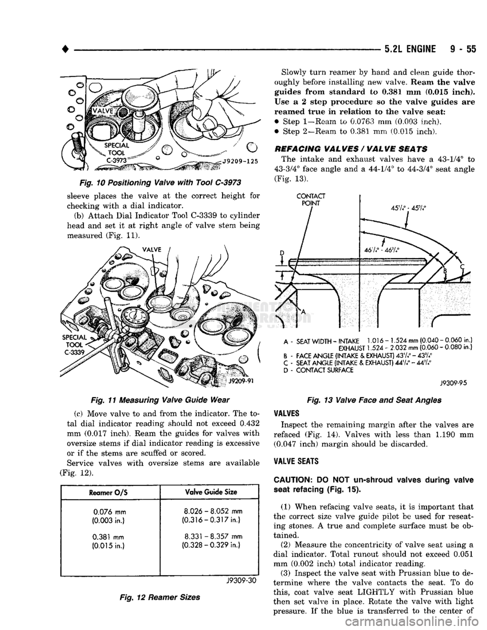
Fig. 10 Positioning Valve with Tool C-3973 sleeve places the valve at the correct height for
checking with a dial indicator.
(b) Attach Dial Indicator Tool C-3339 to cylinder
head and set it at right angle of valve stem being measured (Fig. 11).
Fig. 11 Measuring Valve Guide Wear
(c) Move valve to and from the indicator. The to
tal dial indicator reading should not exceed
0.432
mm
(0.017
inch). Ream the guides for valves with
oversize stems if dial indicator reading is excessive
or if the stems are scuffed or scored. Service valves with oversize stems are available
(Fig. 12).
Reamer
O/S
Valve
Guide
Size
0.076
mm
8.026
-
8.052
mm
(0.003
in.)
(0.316-0.317in.)
0.381
mm
8.331
-
8.357
mm
(0.015
In.)
(0.328-0.329
In.)
J9309-30
Fig. 12 Reamer Sizes
Slowly turn reamer
by
hand
and
clean guide thor
oughly before installing
new
valve. Ream
the valve
guides from standard
to 0,381 mm
(0.015 Inch).
Use
a 2
step procedure
so the
valve guides
are
reamed true
in
relation
to the
valve seat:
• Step
1-Ream
to 0.0763 mm (0.003 inch),
• Step 2—Ream, to 0.381 mm (0.015 inch).
REFACING
VAL
WES
/
WAL
WE
SEATS
The intake and exhaust valves have a 43-1/4° to
43-3/4° face angle and a 44-1/4° to 44-3/4° seat angle
(Fig.
13).
CONTACT
A
-
SEAT
WIDTH
-
INTAKE
1.016-1.524
mm
(0.040
-
0.060
in.)
EXHAUST
1.524 -
2.032
mm
(0.060
-
0.080
in.)
B
-
FACE ANGLE (INTAKE
&
EXHAUST)
437.°
-433//
C
-
SEAT ANGLE (INTAKE
&
EXHAUST)
447/ - 447/
D
-
CONTACT SURFACE
J9309-95
Fig. 13 Valve Face and Seat Angles
VALVES
Inspect the remaining margin after the valves are
refaced (Fig. 14). Valves with less than 1.190 mm (0.047 inch) margin should be discarded.
VALVE
SEATS
CAUTION:
DO NOT
un-shroud valves
during
valve
seat
refacing (Fig.
15).
(1) When refacing valve seats, it is important that
the correct size valve guide pilot be used for reseat ing stones. A true and complete surface must be ob
tained.
(2) Measure the concentricity of valve seat using a
dial indicator. Total runout should not exceed 0.051
mm (0.002 inch) total indicator reading. (3) Inspect the valve seat with Prussian blue to de
termine where the valve contacts the seat. To do
this,
coat valve seat LIGHTLY with Prussian blue
then set valve in place. Rotate the valve with light
pressure. If the blue is transferred to the center of
Page 676 of 1502
•
5.2L
ENGINE
9 - 71
(4)
Carefully install
a
new
upper seal
(refer
to
Up
per Seal Replacement
-
Crankshaft
Installed
proce dure above).
(5) Lightly
oil the
new
lower
seal lips
with
engine
oil.
(6) Install
a new
lower seal
in
bearing
cap
with
yellow paint facing
the
rear
of
engine.
(7) Apply
5
mm (0.20
in)
drop
of Loctite 515,
or
equivalent,
on
each side
of
the rear main bearing cap (Fig. 16). Do not over apply sealant or allow the seal
ant
to
contact the rubber seal. Assemble bearing
cap
to cylinder block immediately after sealant applica
tion.
(8)
To align
the
bearing
cap,
use
cap slot, align
ment dowel and cap bolts. Do
not
remove
excess
ma
terial after assembly. Do
not
strike
rear
cap
more
than
2
times
for
proper engagement. (9) Install
the
rear main bearing cap
with
cleaned
and oiled cap bolts. Alternately tighten the
cap
bolts
to 115 N-m (85
ft.
lbs.) torque*.
(10)
Install
oil
pump.
(11)
Apply
Mopar
Silicone Rubber Adhesive
Seal
ant,
or
equivalent,
at
bearing
cap to
block joint
to
provide cap
to
block and oil pan sealing (Fig. 17). Ap ply enough sealant until
a
small amount
is
squeezed
out. Withdraw nozzle and wipe excess sealant
off
the
oil
pan
seal groove. (12) Immediately install
the oil
pan.
CYLINDER BLOCK
Remove
the
engine assembly from
the
vehicle.
DISASSEMBLE
(1)
Remove
the
cylinder head.
(2)
Remove
the oil
pan.
(3)
Remove
the
piston/connecting
rod
assembly.
CLEANING
Clean cylinder block thoroughly
and
check
ail
core
hole plugs for evidence
of
leaking.
INSPECTION
Examine
block
for
cracks or fractures.
The cylinder walls
should
be
checked
for
out-of-
bound and taper with
Cylinder
Bore Indicator Tool
C-119. The
cylinder block should
be
bored
and
honed
with new pistons
and
rings fitted
if:
•
The cylinder bores show more than 0.127
mm
(0.005
inch) out-of-round.
•
The
cylinder bores show
a
taper
of
more than
0.254
mm
(0.010
inch).
•
The cylinder walls are badly scuffed
or
scored. Boring
and
honing
operation should
be
closely
co
ordinated with
the
fitting
of
pistons
and
rings
so
specified clearances
may
be
maintained.
Refer
to
Standard Service Procedures
in the
begin
ning
of
this
Group
for the
proper
honing
of
cylinder
bores.
OIL
LINE PLUG
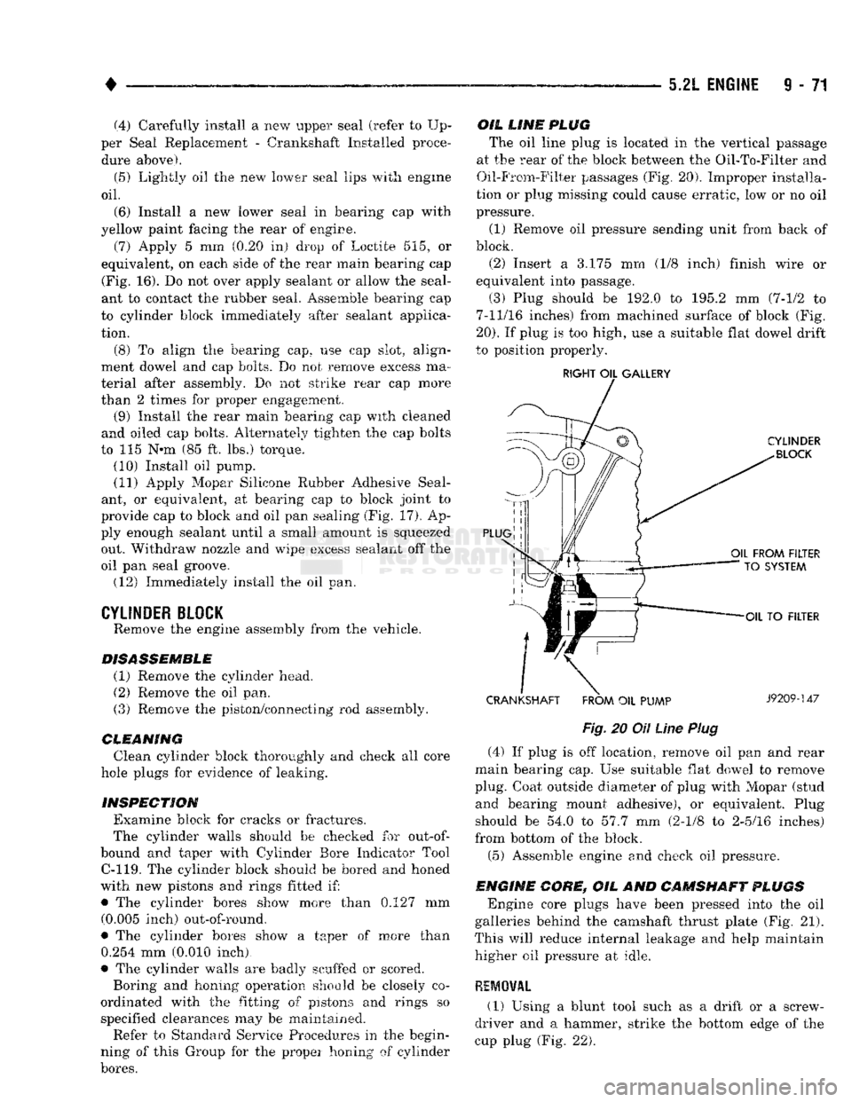
The oil
line
plug
is
located in
the
vertical passage
at
the
rear of the
block
between
the Oil-To-Filter and
Oil-From-Filter passages (Fig, 20). Improper installa
tion
or
plug missing could cause erratic, low
or no oil
pressure.
(1) Remove
oil
pressure sending unit from back
of
block.
(2) Insert
a 3.175 mm (1/8
inch) finish wire
or
equivalent into passage.
(3) Plug should
be 192.0 to 195.2 mm
(7-1/2
to
7-11/16 inches) from machined surface
of
block (Fig.
20).
If
plug
is
too high, use
a
suitable flat dowel drift
to position properly.
RIGHT
OIL
GALLERY
CRANKSHAFT FROM
OIL
PUMP
J9209-147
Fig,
20
Oil
Line
Plug
(4)
If
plug
is off
location, remove
oil pan and
rear
main bearing cap. Use suitable flat dowel
to
remove
plug. Coat outside diameter
of
plug with Mopar (stud and bearing mount adhesive),
or
equivalent. Plug
should
be 54.0 to 57.7 mm
(2-1/8
to
2-5/16 inches)
from bottom
of
the block.
(5) Assemble engine
and
check
oil
pressure.
ENGINE CORE,
OIL AND
CAMSHAFT PLUGS
Engine core plugs have been pressed into
the oil
galleries behind
the
camshaft thrust plate (Fig.
21).
This
will
reduce internal leakage
and
help maintain higher
oil
pressure
at
idle.
REMOVAL (1)
Using
a
blunt tool such
as a
drift
or a
screw
driver
and a
hammer, strike
the
bottom edge
of the
cup plug (Fig.
22).
Page 690 of 1502
•
5.9L
ENGINE
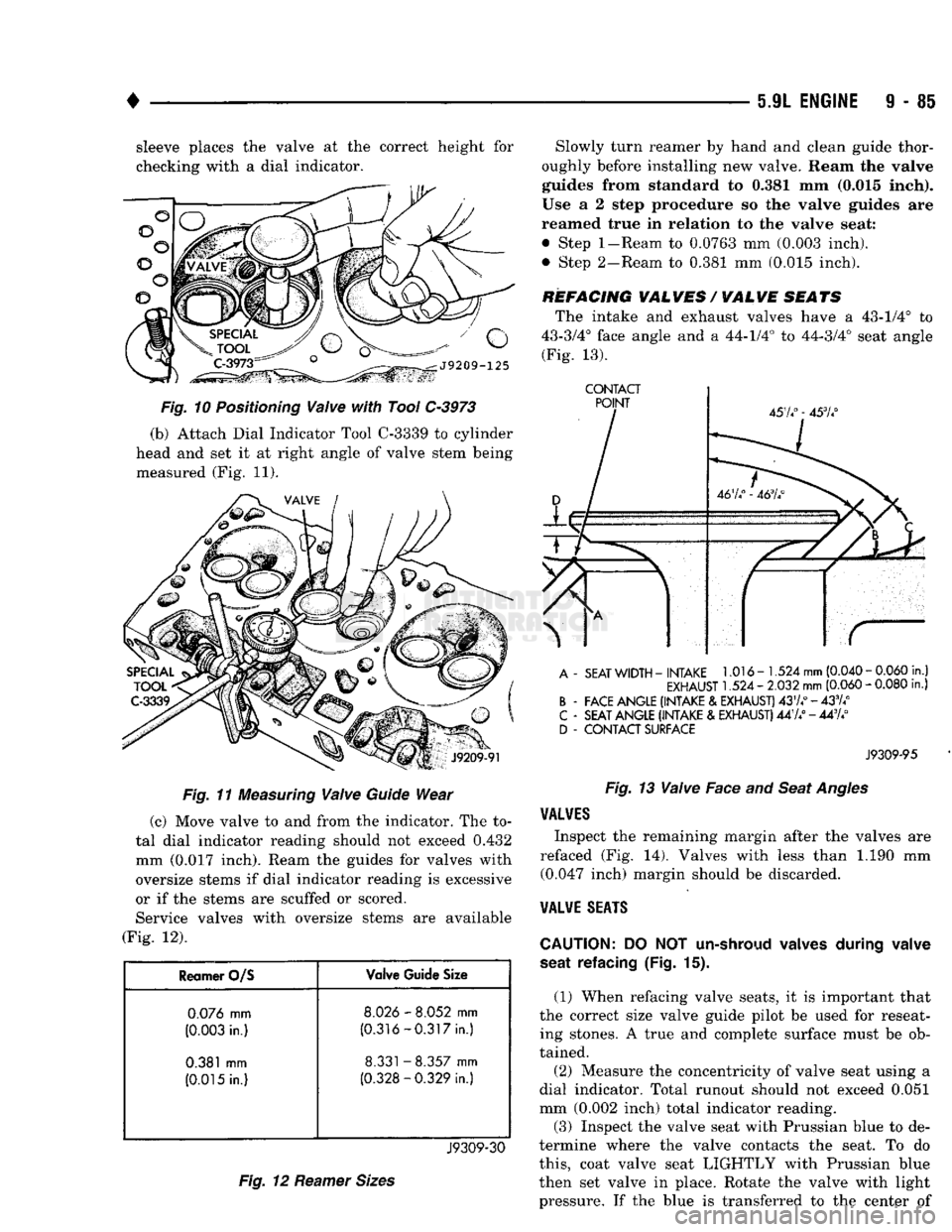
9 - 85 sleeve places the valve at the correct height for
checking with a dial indicator.
Fig.
11
Measuring
Valve
Guide
Wear
(c) Move valve to and from the indicator. The to
tal dial indicator reading should not exceed 0.432
mm (0.017 inch). Ream the guides for valves with
oversize stems if dial indicator reading is excessive
or if the stems are scuffed or scored. Service valves with oversize stems are available
(Fig. 12).
Reamer O/S Valve Guide Size
0.076
mm
8.026
-
8.052
mm
(0.003
in.)
(0.316-0.317
in.)
0.381
mm
8.331
-
8.357
mm
(0.015
in.)
(0.328-0.329
in.)
J9309-30
Fig.
12
Reamer
Sizes
Slowly turn reamer by hand and clean guide thor
oughly before installing new valve. Ream the valve
guides from standard to 0.381 mm (0.015 inch).
Use a 2 step procedure so the valve guides are
reamed true in relation to the valve seat:
• Step
1-Ream
to 0.0763 mm (0.003 inch).
• Step 2-Ream to 0.381 mm (0.015 inch).
REFACING VALVES / VALVE SEATS The intake and exhaust valves have a 43-1/4° to
43-3/4° face angle and a 44-1/4° to 44-3/4° seat angle (Fig. 13).
CONTACT
A
-
SEAT
WIDTH
-
INTAKE
1.016-1.524
mm
(0.040
-
0.060
in.)
EXHAUST
1.524 -
2.032
mm
(0.060
-
0.080
in.)
B
-
FACE ANGLE (INTAKE
&
EXHAUST)
4374°-433/4°
C
-
SEAT ANGLE (INTAKE
&
EXHAUST)
447/ - 443A°
D
-
CONTACT SURFACE
J9309-95
Fig.
13
Valve
Face and
Seat
Angles
VALVES
Inspect the remaining margin after the valves are
refaced (Fig. 14). Valves with less than 1.190 mm (0.047 inch) margin should be discarded.
VALVE
SEATS
CAUTION:
DO NOT
un-shroud valves during valve
seat refacing
(Fig. 15).
(1) When refacing valve seats, it is important that
the correct size valve guide pilot be used for reseat ing stones. A true and complete surface must be ob
tained.
(2) Measure the concentricity of valve seat using a
dial indicator. Total runout should not exceed 0.051
mm (0.002 inch) total indicator reading.
(3)
Inspect the valve seat with Prussian blue to de
termine where the valve contacts the seat. To do
this,
coat valve seat LIGHTLY with Prussian blue
then set valve in place. Rotate the valve with light pressure. If the blue is transferred to the center of
Page 706 of 1502
•
5.9L ENGINE
9 - 101 (7) Apply 5 mm (0.20 in) drop of Loctite 515, or
equivalent, on each side of the rear main bearing cap (Fig. 16). Do not over apply sealant or allow the seal
ant to contact the rubber seal. Assemble bearing cap
to cylinder block immediately after sealant applica
tion.
(8) To align the bearing cap, use cap slot, align
ment dowel and cap bolts. Do not remove excess ma
terial after assembly. Do not strike rear cap more than 2 times for proper engagement.
(9) Install the rear main bearing cap with cleaned
and oiled cap bolts. Alternately tighten the cap bolts
to 115 N-m (85 ft. lbs.) torque.
(10) Install oil pump.
(11) Apply Mopar Silicone Rubber Adhesive Seal
ant, or equivalent, at bearing cap to block joint to
provide cap to block and oil pan sealing (Fig. 17). Ap
ply enough sealant until a small amount is squeezed out. Withdraw nozzle and wipe excess sealant off the
oil pan seal groove. (12) Immediately install the oil pan.
CYLINDER BLOCK
Remove the engine assembly from the vehicle.
DISASSEMBLE
(1) Remove the cylinder head. (2) Remove the oil pan.
(3) Remove the piston/connecting rod assembly.
CLEANING
Clean cylinder block thoroughly and check all core
hole plugs for evidence of leaking.
INSPECTION
Examine block for cracks or fractures.
The cylinder walls should be checked for
out-of-
round and taper with Cylinder Bore Indicator Tool C-119. The cylinder block should be bored and honed
with new pistons and rings fitted if:
• The cylinder bores show more than 0.127 mm (0.005 inch) out-of-round.
• The cylinder bores show a taper of more than 0.254 mm (0.010 inch).
• The cylinder walls are badly scuffed or scored. Boring and honing operation should be closely co
ordinated with the fitting of pistons and rings so specified clearances may be maintained.
Refer to Standard Service Procedures in the begin
ning of this Group for the proper honing of cylinder
bores.
OIL LINE
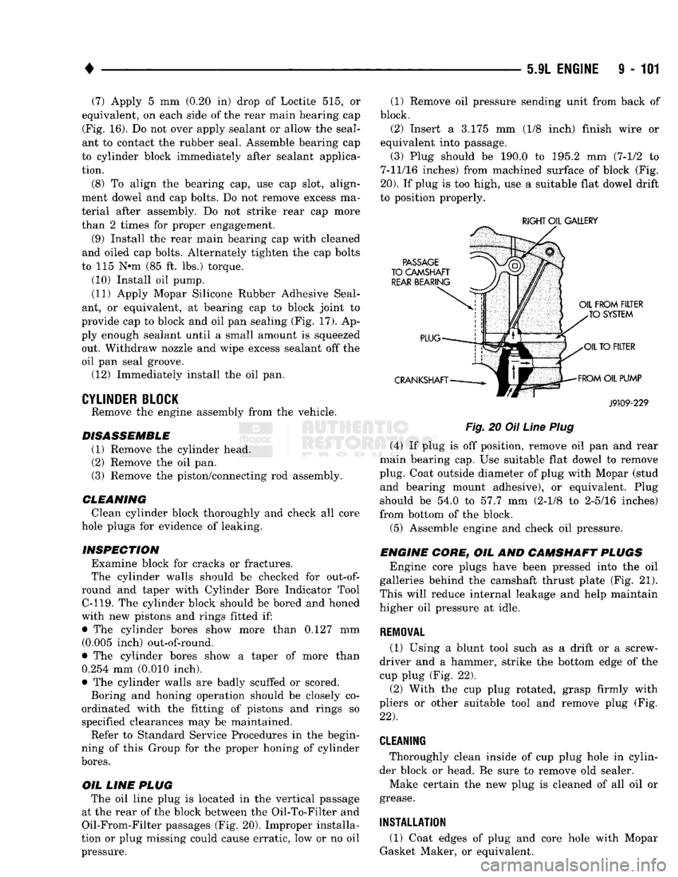
PLUG The oil line plug is located in the vertical passage
at the rear of the block between the Oil-To-Filter and
Oil-From-Filter passages (Fig. 20). Improper installa
tion or plug missing could cause erratic, low or no oil
pressure. (1) Remove oil pressure sending unit from back of
block. (2) Insert a 3.175 mm (1/8 inch) finish wire or
equivalent into passage.
(3) Plug should be 190.0 to 195.2 mm (7-1/2 to
7-11/16 inches) from machined surface of block (Fig.
20).
If plug is too high, use a suitable flat dowel drift
to position properly.
RIGHT OIL GALLERY
J9109-229
Fig.
20 Oil
Line
Plug
(4) If plug is off position, remove oil pan and rear
main bearing cap. Use suitable flat dowel to remove
plug. Coat outside diameter of plug, with Mopar (stud and bearing mount adhesive), or equivalent. Plug
should be 54.0 to 57.7 mm (2-1/8 to 2-5/16 inches)
from bottom of the block.
(5) Assemble engine and check oil pressure.
ENGINE CORE,
OIL AND
CAMSHAFT
PLUGS Engine core plugs have been pressed into the oil
galleries behind the camshaft thrust plate (Fig. 21).
This will reduce internal leakage and help maintain
higher oil pressure at idle.
RE10¥AL
(1) Using a blunt tool such as a drift or a screw
driver and a hammer, strike the bottom edge of the
cup plug (Fig. 22).
(2) With the cup plug rotated, grasp firmly with
pliers or other suitable tool and remove plug (Fig.
22).
CLEANING
Thoroughly clean inside of cup plug hole in cylin
der block or head. Be sure to remove old sealer.
Make certain the new plug is cleaned of all oil or
grease.
INSTALLATION
(1) Coat edges of plug and core hole with Mopar
Gasket Maker, or equivalent.
Page 850 of 1502
•
FUEL SYSTEM
14-31 through different system components. These compo
nents are referred to as Powertrain Control Module
(PCM) Outputs. The sensors and switches that pro
vide inputs to the PCM are considered Powertrain Control Module (PCM) Inputs.
The PCM adjusts ignition timing based upon in
puts it receives from sensors that react to: engine rpm, manifold absolute pressure, engine coolant tem
perature, throttle position, transmission gear selec
tion (automatic transmission), vehicle speed and the
brake switch.
The PCM adjusts idle speed based on inputs it re
ceives from sensors that react to: throttle position,
vehicle speed, transmission gear selection, engine coolant temperature and from inputs it receives from
the air conditioning clutch switch and brake switch.
Based on inputs that it receives, the PCM adjusts
ignition coil dwell. The PCM also adjusts the gener
ator charge rate through control of the generator
field and provides speed control operation.
Powertrain Control Module (PCM) Inputs:
• Generator output • A/C request (if equipped with factory A/C)
• A/C select (if equipped with factory A/C)
• Auto shut down (ASD) sense
• Charge air temperature sensor
• Battery voltage
• Brake switch
• Engine coolant temperature sensor
• Crankshaft position sensor • Ignition circuit sense (ignition switch in run posi
tion)
• Manifold absolute pressure (MAP) sensor
• Overdrive/override switch
• Oxygen sensor(s)
• Park/neutral switch (auto, trans, only)
• SCI receive (DRB II connection) • Speed control resume switch
• Speed control set switch • Speed control on/off switch
• Camshaft position sensor signal
• Throttle position sensor
• Vehicle speed sensor
• Sensor return
• Power ground
• Signal ground Powertrain Control Module (PCM) Outputs:
• A/C clutch relay
• Idle air control (IAC) motor
• Auto shut down (ASD) relay
• Generator field
• Malfunction indicator lamp
• Service reminder indicator lamp
• EGR valve control solenoid • Fuel injectors
• Fuel pump relay
• Ignition coil • EVAP canister purge solenoid
• SCI transmit (DRB II connection)
• Shift indicator lamp (manual transmission only)
• Speed control vacuum solenoid
• Speed control vent solenoid
• Tachometer (on instrument panel, if equipped) The powertrain control module (PCM) contains a
voltage convertor. This converts battery voltage to a
regulated 8.0 volts. It is used to power the crankshaft
position sensor and camshaft position sensor. The
PCM also provides a five (5) volt supply for the man ifold absolute pressure (MAP) sensor and throttle po
sition sensor (TPS).
AIR
CONDITIONING
(A/C)
CONTROLS-PCM
INPUT
The A/C control system information applies to fac
tory installed air conditioning units. A/C SELECT SIGNAL: When the A/C switch is
in the ON position and the A/C low pressure switch
is closed, an input signal is sent to the powertrain
control module (PCM). The signal informs the PCM
that the A/C has been selected. The PCM adjusts idle speed to a pre-programmed rpm through the idle air
control (IAC) motor to compensate for increased en
gine load. A/C REQUEST SIGNAL: Once A/C has been se
lected, the powertrain control module (PCM) receives
the A/C request signal from the evaporator switch.
The input indicates that the evaporator temperature is in the proper range for A/C application. The PCM
uses this input to cycle the A/C compressor clutch (through the A/C relay). It will also determine the
correct engine idle speed through the idle air control (IAC) motor position. If the A/C low pressure switch opens (indicating a
low refrigerant level), the PCM will not receive an
A/C select signal. The PCM will then remove the ground from the A/C relay. This will deactivate the
A/C compressor clutch. If the evaporator switch opens, (indicating that
evaporator is not in proper temperature range), the
PCM will not receive the A/C request signal. The
PCM will then remove the ground from the A/C re lay, deactivating the A/C compressor clutch.
AUTOMATIC SHUT DOWN
(ASD)
SENSE-PCM INPUT
A 12 volt signal at this input indicates to the PCM
that the ASD has been activated. The ASD relay is located in the engine compartment (Fig. 2). It is used
to connect the oxygen sensor(s) heater element, igni
tion coil, generator field winding and fuel injectors to 12 volt + power supply. This input is used only to sense that the ASD relay
is energized. If the powertrain control module (PCM)
does not see 12 volts at this input when the ASD
should be activated, it will set a diagnostic trouble
code (DTC).