1993 DODGE TRUCK service indicator
[x] Cancel search: service indicatorPage 855 of 1502
trol (IAC) stepper motor position to compensate for
increased engine load from the A/C compressor.
By switching the ground path for the relay on and
off, the PCM is able to cycle the A/C compressor
clutch. This is based on changes in engine operating
conditions. If, during A/C operation, the PCM senses
low idle speeds or a wide open throttle condition, it
will de-energize the relay. This prevents A/C clutch engagement. The relay will remain de-energized un
til the idle speed increases or the wide open throttle condition exceeds 15 seconds or no longer exists. The
PCM will also de-energize the relay if coolant tem
perature exceeds 125°C (257°F).
IDLE
AIR
CONTROL
(IAC)
MOTOR-PCM OUTPUT
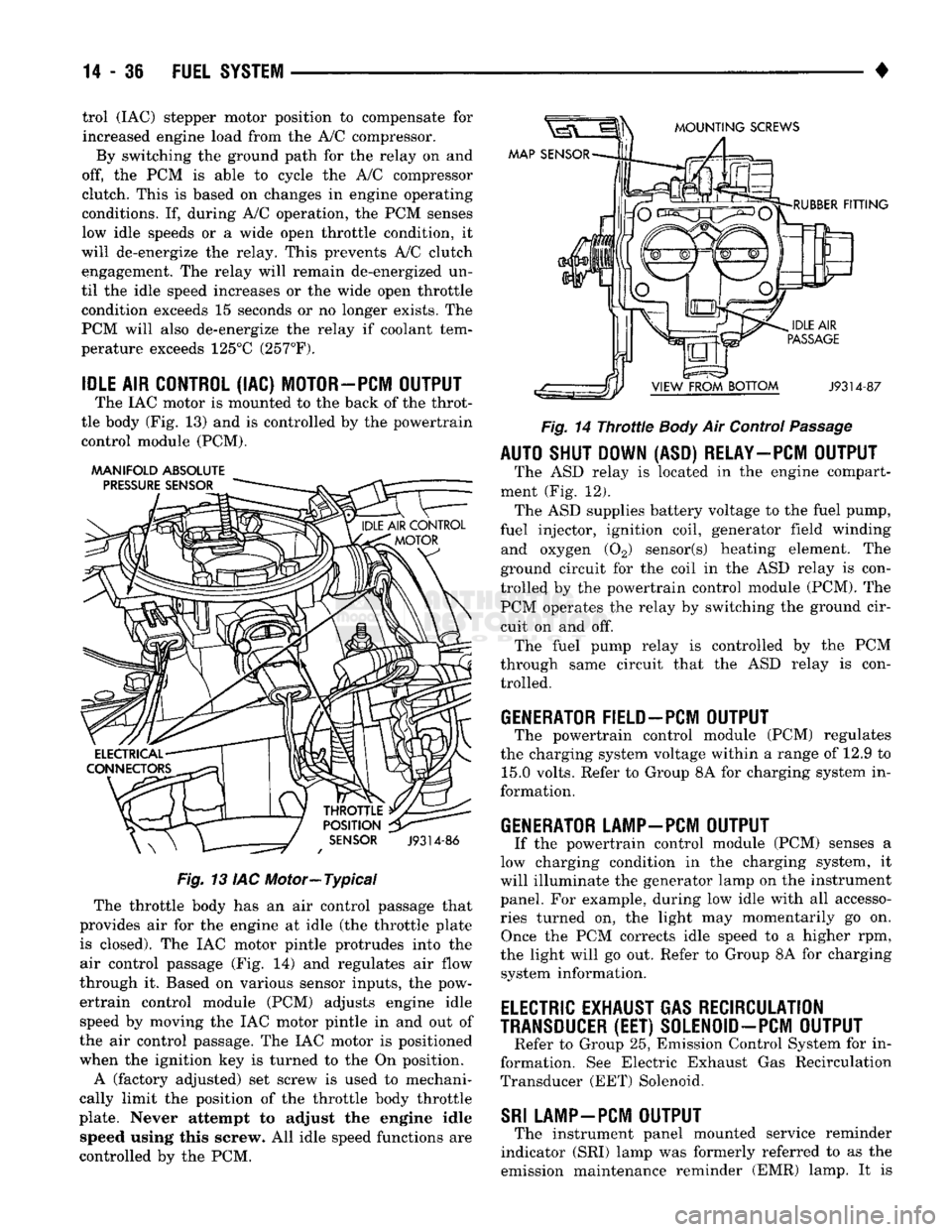
The IAC motor is mounted to the back of the throt
tle body (Fig. 13) and is controlled by the powertrain control module (PCM).
AAANIFOLD ABSOLUTE
PRESSURE
SENSOR
MOUNTING
SCREWS
MAP SENSOR
THROTTLE
POSITION
SENSOR
J9314-86
Fig.
13 IAC Motor—Typical The throttle body has an air control passage that
provides air for the engine at idle (the throttle plate is closed). The IAC motor pintle protrudes into the
air control passage (Fig. 14) and regulates air flow
through it. Based on various sensor inputs, the pow
ertrain control module (PCM) adjusts engine idle speed by moving the IAC motor pintle in and out of
the air control passage. The IAC motor is positioned
when the ignition key is turned to the On position.
A (factory adjusted) set screw is used to mechani
cally limit the position of the throttle body throttle
plate. Never attempt to adjust the engine idle speed using this screw. All idle speed functions are
controlled by the PCM.
RUBBER
FITTING
J9314-87
Fig.
14
Throttle
Body
Air Control
Passage
AUTO SHUT DOWN (ASD) RELAY—PCM OUTPUT
The ASD relay is located in the engine compart
ment (Fig. 12). The ASD supplies battery voltage to the fuel pump,
fuel injector, ignition coil, generator field winding and oxygen (02) sensor(s) heating element. The
ground circuit for the coil in the ASD relay is con
trolled by the powertrain control module (PCM). The PCM operates the relay by switching the ground cir
cuit on and off. The fuel pump relay is controlled by the PCM
through same circuit that the ASD relay is con trolled.
GENERATOR FIELD-PCM OUTPUT
The powertrain control module (PCM) regulates
the charging system voltage within a range of 12.9 to 15.0 volts. Refer to Group 8A for charging system in
formation.
GENERATOR LAMP-PCM OUTPUT
If the powertrain control module (PCM) senses a
low charging condition in the charging system, it
will illuminate the generator lamp on the instrument
panel. For example, during low idle with all accesso
ries turned on, the light may momentarily go on. Once the PCM corrects idle speed to a higher rpm,
the light will go out. Refer to Group 8A for charging system information.
ELECTRIC
EXHAUST GAS RECIRCULATION
TRANSDUCER
(EET)
S0LEN0ID-PCM OUTPUT
Refer to Group 25, Emission Control System for in
formation. See Electric Exhaust Gas Recirculation
Transducer (EET) Solenoid.
SRI
LAMP-PCM OUTPUT
The instrument panel mounted service reminder
indicator (SRI) lamp was formerly referred to as the
emission maintenance reminder (EMR) lamp. It is
Page 856 of 1502
•
FUEL SYSTEM
14 - 37 used only on vehicles equipped with the 5.9L heavy
duty cycle (HDC) engine. Refer to Group 25, Emis
sion Control System for information.
EVAP CANISTER PURGE SOLENOID-PCM
OUTPUT
Refer to Group 25, Emission Control System. See
EVAP Canister Purge Solenoid.
FUEL INJECTORS-PCM
OUTPUT
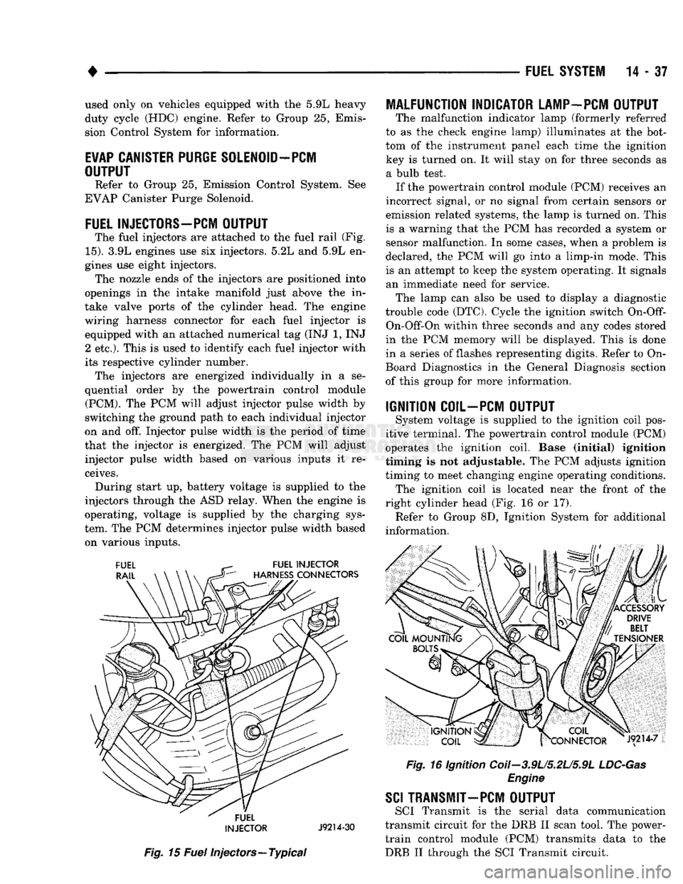
The fuel injectors are attached to the fuel rail (Fig.
15).
3.9L engines use six injectors. 5.2L and 5.9L en
gines use eight injectors. The nozzle ends of the injectors are positioned into
openings in the intake manifold just above the in
take valve ports of the cylinder head. The engine
wiring harness connector for each fuel injector is equipped with an attached numerical tag (INJ 1, INJ 2 etc.). This is used to identify each fuel injector with
its respective cylinder number. The injectors are energized individually in a se
quential order by the powertrain control module (PCM). The PCM will adjust injector pulse width by
switching the ground path to each individual injector
on and off. Injector pulse width is the period of time
that the injector is energized. The PCM will adjust injector pulse width based on various inputs it re
ceives. During start up, battery voltage is supplied to the
injectors through the ASD relay. When the engine is
operating, voltage is supplied by the charging sys
tem. The PCM determines injector pulse width based on various inputs.
FUEL
INJECTOR
J9214-30
Fig.
15
Fuel
injectors—Typical
MALFUNCTION INDICATOR LAMP-PCM OUTPUT
The malfunction indicator lamp (formerly referred
to as the check engine lamp) illuminates at the bot
tom of the instrument panel each time the ignition key is turned on. It will stay on for three seconds as a bulb test. If the powertrain control module (PCM) receives an
incorrect signal, or no signal from certain sensors or
emission related systems, the lamp is turned on. This
is a warning that the PCM has recorded a system or
sensor malfunction. In some cases, when a problem is
declared, the PCM will go into a limp-in mode. This
is an attempt to keep the system operating. It signals an immediate need for service. The lamp can also be used to display a diagnostic
trouble code (DTC). Cycle the ignition switch
On-Off-
On-Off-On within three seconds and any codes stored
in the PCM memory will be displayed. This is done
in a series of flashes representing digits. Refer to On-
Board Diagnostics in the General Diagnosis section
of this group for more information.
IGNITION COIL-PCM OUTPUT
System voltage is supplied to the ignition coil pos
itive terminal. The powertrain control module (PCM)
operates the ignition coil. Base (initial) ignition
timing is not adjustable. The PCM adjusts ignition
timing to meet changing engine operating conditions. The ignition coil is located near the front of the
right cylinder head (Fig. 16 or 17). Refer to Group 8D, Ignition System for additional
information.
Fig.
16 Ignition Coii-3.9U5.2U5.9L
LDC-Gas
Engine
SCI
TRANSMIT—PCM OUTPUT
SCI Transmit is the serial data communication
transmit circuit for the DRB II scan tool. The power- train control module (PCM) transmits data to the DRB II through the SCI Transmit circuit.
Page 879 of 1502
14 - SO
FUEL
SYSTEM
•
HIGH
AND LOW
LIMITS
The powertrain control module (PCM) compares in
put signal voltages from each input device. It will es
tablish high and low limits that are programmed into it for that device. If the input voltage is not
within specifications and other diagnostic trouble code (DTC) criteria are met, a DTC will be stored in
memory. Other DTC criteria might include engine
rpm limits or input voltages from other sensors or switches. The other inputs might have to be sensed
by the PCM when it senses a high or low input volt age from the control system device in question.
ACCESSING DIAGNOSTIC TROUBLE CODES A stored diagnostic trouble code (DTC) can be dis
played by cycling the ignition key On-Off-On-Off-On
within three seconds and observing the malfunction indicator lamp. This lamp was formerly referred to
as the check engine lamp. The lamp is located on the
instrument panel.
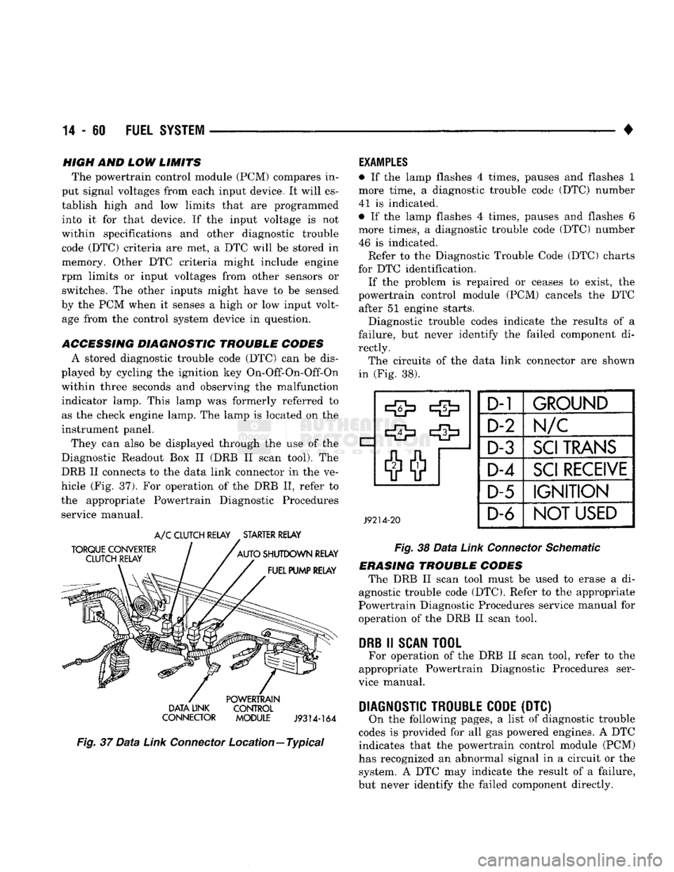
They can also be displayed through the use of the
Diagnostic Readout Box II (DRB II scan tool). The
DRB II connects to the data link connector in the ve
hicle (Fig. 37). For operation of the DRB II, refer to
the appropriate Powertrain Diagnostic Procedures service manual.
TORQUE CONVERTER
CLUTCH RELAY
A/C
CLUTCH RELAY
.
STARTER RELAY
AUTO
SHUTDOWN RELAY FUEL PUMP RELAY POWERTRAIN
DATA LINK CONTROL
CONNECTOR MODULE
J9314-164
Fig.
37
Data
Link
Connector
Location—Typical
EXAMPLES
• If the lamp flashes 4 times, pauses and flashes 1
more time, a diagnostic trouble code (DTC) number
41 is indicated.
• If the lamp flashes 4 times, pauses and flashes 6
more times, a diagnostic trouble code (DTC) number
46 is indicated. Refer to the Diagnostic Trouble Code (DTC) charts
for DTC identification. If the problem is repaired or ceases to exist, the
powertrain control module (PCM) cancels the DTC after 51 engine starts.
Diagnostic trouble codes indicate the results of a
failure, but never identify the failed component di
rectly. The circuits of the data link connector are shown
in (Fig. 38).
J9214-20
D-1
GROUND
D-2 Im/c
D-3
SCI
TRANS
D-4
SCI
RECEIVE
D-5
IGNITION
D-6
NOT
USED
Fig.
38
Data
Link
Connector
Schematic
ERASING TROUBLE CODES The DRB II scan tool must be used to erase a di
agnostic trouble code (DTC). Refer to the appropriate
Powertrain Diagnostic Procedures service manual for operation of the DRB II scan tool.
DRB
II
SCAN
TOOL
For operation of the DRB II scan tool, refer to the
appropriate Powertrain Diagnostic Procedures ser
vice manual.
DIAGNOSTIC TROUBLE CODE
(DTC) On the following pages, a list of diagnostic trouble
codes is provided for all gas powered engines. A DTC indicates that the powertrain control module (PCM)
has recognized an abnormal signal in a circuit or the system. A DTC may indicate the result of a failure,
but never identify the failed component directly.
Page 901 of 1502
14 - 82
FUEL 'SYSTEM
—. — ~—— — «
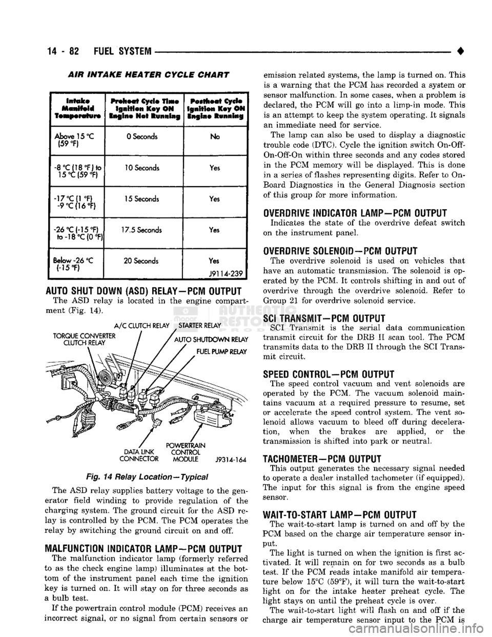
INTAKE HEATER CYCLE CHART
Intake
featperafwre
Preheat
Cycle
Time
Ignition
l£ey ON
Engine
Not
Running
Pestheat
Cycle
Ignition
Key ON
Snglne Running
Above
15
°C
(59
°F)
0 Seconds
No
-8°C(18°F)to
15°C (59
°F)
10
Seconds
Yes
-17°C(1
°F)
-9
°C(]6°F)
15
Seconds
Yes
«2d°C(-15°F)
to-18°C(0
°F) 17.5
Seconds
Yes
Below-26
°C (-15
*F)
20 Seconds
Yes
J9114-239
AUTO SHUT DOWN (ASD) RELAY-PCM OUTPUT
The ASD relay is located in the engine compart
ment (Fig. 14).
TORQUE CONVERTER
CLUTCH RELAY A/C CLUTCH RELAY STARTER RELAY
AUTO SHUTDOWN RELAY FUEL PUMP RELAY DATA LINK
CONNECTOR
POWERTRAIN
CONTROL MODULE
J9314-164
Fig.
14 Relay Location—Typical The ASD relay supplies battery voltage to the gen
erator field winding to provide regulation of the
charging system. The ground circuit for the ASD re
lay is controlled by the PCM. The PCM operates the
relay by switching the ground circuit on and off.
MALFUNCTION INDICATOR LAMP-PCM OUTPUT
The malfunction indicator lamp (formerly referred
to as the check engine lamp) illuminates at the bot
tom of the instrument panel each time the ignition
key is turned on. It will stay on for three seconds as
a bulb test. If the powertrain control module (PCM) receives an
incorrect signal, or no signal from certain sensors or emission related systems, the lamp is turned on. This
is a warning that the PCM has recorded a system or
sensor malfunction. In some cases, when a problem is
declared, the PCM will go into a limp-in mode. This is an attempt to keep the system operating. It signals
an immediate need for service.
The lamp can also be used to display a diagnostic
trouble code (DTC). Cycle the ignition switch
On-Off-
On-Off-On within three seconds and any codes stored
in the PCM memory will be displayed. This is done
in a series of flashes representing digits. Refer to On-
Board Diagnostics in the General Diagnosis section
of this group for more information.
OVERDRIVE
INDICATOR LAMP-PCM OUTPUT
Indicates the state of the overdrive defeat switch
on the instrument panel.
OVERDRIVE
S0LEN0ID-PCM OUTPUT
The overdrive solenoid is used on vehicles that
have an automatic transmission. The solenoid is op erated by the PCM. It controls shifting in and out of
overdrive through the overdrive solenoid. Refer to Group 21 for overdrive solenoid service.
SCI
TRANSMIT—PCM OUTPUT
SCI Transmit is the serial data communication
transmit circuit for the DRB II scan tool. The PCM
transmits data to the DRB II through the SCI Trans
mit circuit.
SPEED
C0NTR0L-PCM OUTPUT
The speed control vacuum and vent solenoids are
operated by the PCM. The vacuum solenoid main
tains vacuum at a required pressure to resume, set or accelerate the speed control system. The vent so
lenoid allows vacuum to bleed off during decelera
tion, when the brakes are applied, or the
transmission is shifted into park or neutral.
TACHOMETER-PCM
OUTPUT
This output generates the necessary signal needed
to operate a dealer installed tachometer (if equipped).
The input for this signal is from the engine speed sensor.
WAIT-TO-START LAMP-PCM OUTPUT
The wait-to-start lamp is turned on and off by the
PCM based on the charge air temperature sensor in
put. The light is turned on when the ignition is first ac
tivated. It will remain on for two seconds as a bulb
test. If the PCM reads intake manifold air tempera
ture below 15°C (59°F), it will turn the wait-to-start light on for the intake heater preheat cycle. The
light stays on until the preheat cycle is over. The wait-to-start light will flash on and off if the
charge air temperature sensor input to the PCM is
Page 913 of 1502
14
- 94
FUEL
SYSTEM
•
THROTTLE POSITION
SENSOR
TEST
CAUTION;
Before checking
the
TPS,
the
throttle
linkage must
be
checked
for
correct
adjustment.
The
throttle
lever must
contact
the low idle
speed screw.
The
throttle
lever must reach breakover when
the
throttle
is
wide
open. Refer
to the
Accelerator Pedal and
Throttle
Cable section
of
Group
14,
Fuel Systems.
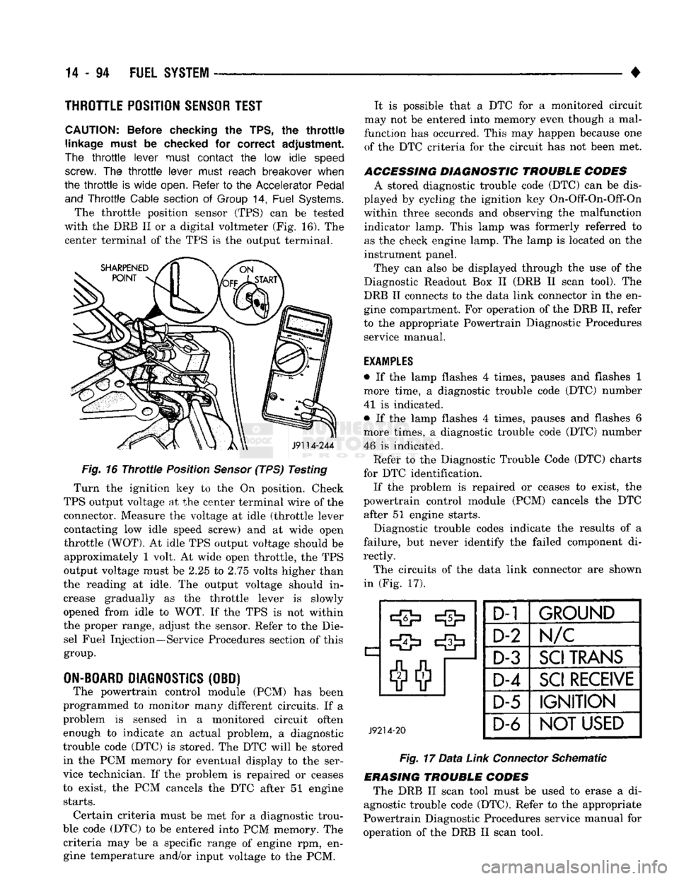
The throttle position sensor (TPS) can be tested
with the DRB II or a digital voltmeter (Fig. 16). The center terminal of the TPS is the output terminal.
J9114-244
Fig.
16
Throttle
Position
Sensor
(TPS) Testing
Turn the ignition key to the On position. Check
TPS output voltage at the center terminal wire of the connector. Measure the voltage at idle (throttle lever contacting low idle speed screw) and at wide open
throttle
(WOT).
At idle TPS output voltage should be approximately 1 volt. At wide open throttle, the TPS
output voltage must be 2.25 to 2.75 volts higher than
the reading at idle. The output voltage should in
crease gradually as the throttle lever is slowly
opened from idle to WOT. If the TPS is not within
the proper range, adjust the sensor. Refer to the Die sel Fuel Injection—Service Procedures section of this
group.
ON-BOARD
DIAGNOSTICS
(OBD) The powertrain control module (PCM) has been
programmed to monitor many different circuits. If a
problem is sensed in a monitored circuit often enough to indicate an actual problem, a diagnostic
trouble code (DTC) is stored. The DTC will be stored in the PCM memory for eventual display to the ser
vice technician. If the problem is repaired or ceases
to exist, the PCM cancels the DTC after 51 engine
starts.
Certain criteria must be met for a diagnostic trou
ble code (DTC) to be entered into PCM memory. The criteria may be a specific range of engine rpm, engine temperature and/or input voltage to the PCM. It is possible that a DTC for a monitored circuit
may not be entered into memory even though a mal
function has occurred. This may happen because one of the DTC criteria for the circuit has not been met.
ACCESSING DIAGNOSTIC TROUBLE CODES A stored diagnostic trouble code (DTC) can be dis
played by cycling the ignition key On-Off-On-Off-On
within three seconds and observing the malfunction indicator lamp. This lamp was formerly referred to
as the check engine lamp. The lamp is located on the
instrument panel.
They can also be displayed through the use of the
Diagnostic Readout Box II (DRB II scan tool). The
DRB II connects to the data link connector in the en
gine compartment. For operation of the DRB II, refer
to the appropriate Powertrain Diagnostic Procedures service manual.
EXAMPLES
• If the lamp flashes 4 times, pauses and flashes 1
more time, a diagnostic trouble code (DTC) number
41 is indicated.
• If the lamp flashes 4 times, pauses and flashes 6
more times, a diagnostic trouble code (DTC) number 46 is indicated. Refet* to the Diagnostic Trouble Code (DTC) charts
for DTC identification. If the problem is repaired or ceases to exist, the
powertrain control module (PCM) cancels the DTC after 51 engine starts.
Diagnostic trouble codes indicate the results of a
failure, but never identify the failed component di
rectly.
The circuits of the data link connector are shown
in (Fig. 17).
J9214-20
D-1
1
GROUND
D-2
N/C
D-3
SCI
TRANS
D-4
SCI
RECEIVE
D-5 IGNITION
D-6
NOT USED
Fig.
17
Data
Link
Connector
Schematic
ERASING TROUBLE CODES The DRB II scan tool must be used to erase a di
agnostic trouble code (DTC). Refer to the appropriate
Powertrain Diagnostic Procedures service manual for
operation of the DRB II scan tool.
Page 1064 of 1502
•
G360
TRANSMISSION
OVERHAUL
21 - 63 The retainer seals have a small spring around the in
ner part of the seal. Be sure each seal is installed
with this spring facing the case interior.
The snap rings should all be replaced. Eeusing
snap rings is not recommended.
Shift
Cover
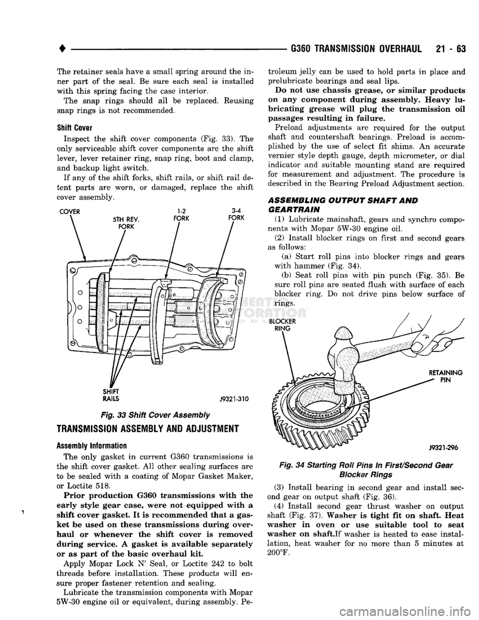
Inspect the shift cover components (Fig. 33). The
only serviceable shift cover components are the shift
lever, lever retainer ring, snap ring, boot and clamp, and backup light switch.
If any of the shift forks, shift rails, or shift rail de
tent parts are worn, or damaged, replace the shift cover assembly.
COVER 1-2 3-4
SHIFT
RAILS
J9321-310
Fig.
33 Shift
Cover
Assembly
TRANSMISSION
ASSEMBLY
AND
ADJUSTMENT
Assembly
Information
The only gasket in current G360 transmissions is
the shift cover gasket. All other sealing surfaces are
to be sealed with a coating of Mopar Gasket Maker, or Loctite 518.
Prior production G360 transmissions with the
early style gear case, were not equipped with a shift cover gasket. It is recommended that a gas
ket be used on these transmissions during over
haul or whenever the shift cover is removed during service. A gasket is available separately
or as part of the basic overhaul kit.
Apply Mopar Lock N' Seal, or Loctite 242 to bolt
threads before installation. These products will en sure proper fastener retention and sealing.
Lubricate the transmission components with Mopar
5W-30 engine oil or equivalent, during assembly. Pe troleum jelly can be used to hold parts in place and
prelubricate bearings and seal lips.
Do not use chassis grease, or similar products
on any component during assembly. Heavy lu
bricating grease will plug the transmission oil
passages resulting in failure. Preload adjustments are required for the output
shaft and countershaft bearings. Preload is accom
plished by the use of select fit shims. An accurate
vernier style depth gauge, depth micrometer, or dial indicator and suitable mounting stand are required
for measurement and adjustment. The procedure is described in the Bearing Preload Adjustment section.
ASSEMBLING OUTPUT SHAFT AND
GEARTRAIN
(1) Lubricate mainshaft, gears and synchro compo
nents with Mopar 5W-30 engine oil. (2) Install blocker rings on first and second gears
as follows:
(a) Start roll pins into blocker rings and gears
with hammer (Fig. 34). (b) Seat roll pins with pin punch (Fig. 35). Be
sure roll pins are seated flush with surface of each
blocker ring. Do not drive pins below surface of
rings.
Fig.
34 Starting
Roll
Pins
In
First/Second
Gear
Blocker
Rings
(3) Install bearing in second gear and install sec
ond gear on output shaft (Fig. 36).
(4) Install second gear thrust washer on output
shaft (Fig. 37). Washer is tight fit on shaft. Heat
washer in oven or use suitable tool to seat
washer on shaft.If washer is heated to ease instal
lation, heat washer for no more than 5 minutes at
200°F.
Page 1344 of 1502
•
NP205 TRANSFER
CASE
21 - 343 Leakage from other sources (engine, transmission,
etc.) can be blown back onto the transfer case by air
flow under the vehicle. A blocked transfer case vent
can also cause leakage at the shaft seals due to in
ternal pressure build up.
Overfilling the transfer case can force fluid out the
vent and be mistaken for a leak. Correct fluid level checking methods should prevent overfill problems.
Checking
Fluid Level The correct method of checking transfer case fluid
level requires that the vehicle be level.
If fluid level is checked with the vehicle parked on
the shop floor, be sure the floor area used is level. If a hoist is used, a drive-on, or swivel arm type is pre
ferred.
Allow the transfer case fluid to settle for a minute
or so before checking. Correct fluid level is to the
bottom edge of the fill plug hole.
HARD SHIFTING
Hard shifting is generally caused by:
• misadjusted or binding linkage
• loose linkage or driveline components
• torque loads caused by 4WD operation on hard
paved surfaces • improper shifting techniques
• lack of lubricant which caused internal wear and
damage.
Loose linkage or driveline components are a result
of improperly tightened, stripped, or missing fasten
ers.
Remember that loose crossmember and mounting
parts can also generate a hard shift condition.
Torque loads in the transfer case can cause hard
shifting or even prevent shifting. Such loads are gen
erally a product of extensive operation on hard,
paved surfaces in 4WD range, unequal size tires, or
by mismatched front/rear axle gear ratios.
Linkage adjustment should be performed as de
scribed in the service section. Improper shift and op
erating techniques can be corrected by instructing
the driver. Internal component damage will require
overhaul to correct.
Failure to lubricate the shift linkage at recom
mended intervals will cause the linkage to bind. If
bind is severe enough to cause hard shifting, the linkage will have to be removed in order to correct
the condition. The linkage can be soaked in auto
matic transmission fluid if necessary. The fluid will
break up accumulated rust and corrosion.
NOISE
Some transfer case operating noise is normal. The
rotating gear train can produce sounds that may be
come audible at higher speeds and loads. However,
unusual noise is an indicator that internal compo nents may be worn or damaged. Low lubricant levels are a frequent cause of noisy
operation. Insufficient lubricant will lead to over
heating, subsequent damage to bearing and gear sur
faces and hard shifting.
Transfer case bearing noise is higher in pitch than
gear noise. If the unit is noisy in 4WD range only,
the front shaft bearings are probably at fault. If the unit is noisy in all ranges, an overhaul will be nec
essary to locate the faulty bearing.
Gear noise is lower in pitch and usually most no
ticeable when engaged and under load. Gear noise in
4WD drive range only is an indicator that the front shaft gears are damaged. Noise in all ranges could be
the idler or drive gears. An overhaul will be neces sary to determine which is at fault.
Frequently, suspected transfer case noise may actu
ally originate from another driveline component. The
proximity of other driveline components can some
times make it difficult to pinpoint the noise source.
TRANSFER CASE OPERATIONAL CHECK
The transfer case should not be removed until di
agnosis indicates the unit has actually malfunc
tioned. If a transfer case problem is suspected, check and verify operation before attempting repair. A
transfer case operational check may reveal that a
problem is actually related to another driveline com ponent.
(1) Raise vehicle on a hoist that will allow all four
wheels to rotate. (2) Check lubricant level. If lubricant level is low,
check for leaks at the bearing and seal retainers,
yokes,
drain/fill plugs, PTO cover and vent. (3) If vehicle is equipped with locking hubs, en
gage hubs. (4) Start engine, shift transmission into gear and
operate transfer case in all ranges. Observe propeller shaft action, shift efforts and operational sound lev
els as follows: (a) Only the rear propeller shaft should rotate in
two-wheel drive. Both propeller shafts should both
rotate in four-wheel drive high and low ranges. (b) If the front propeller shaft did not rotate in
either four-wheel drive range, the transfer case shift components may be worn or damaged. Or, if
the front shaft did rotate but the front wheels did
not, check the front axle shift mechanism and the locking hubs (if equipped). (c) If both propeller shafts rotate in four-wheel
drive but the wheels on one axle did not rotate, the
problem is in the axle. (d) If neither propeller shaft rotates in any
range, the problem is in the transmission or trans fer case. To determine which component is at fault,
proceed to next step. (5) Determine if fault is with transfer case or
transmission as follows:
Page 1376 of 1502
•
WHEELS
AND
TIRES
22 - 7 move and install dual rear wheels only when the
proper wrench is available.
INSTALLATION
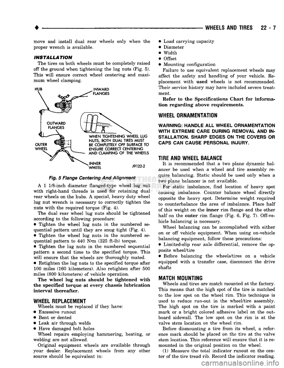
The tires on both wheels must be completely raised
off the ground when tightening the lug nuts (Fig. 5).
This will ensure correct wheel centering and maxi mum wheel clamping.
HUB
^
INWARD
Fig.
5 Flange Centering And
Alignment
A 1
1/8-inch
diameter flanged-type wheel lug nut
with right-hand threads is used for retaining dual rear wheels on the hubs. A special, heavy duty wheel lug nut wrench is necessary to correctly tighten the nuts with the required torque (Fig. 4).
The dual rear wheel lug nuts should be tightened
according to the following procedure:
• Tighten the wheel lug nuts in the numbered se
quential pattern until they are snug tight (Fig. 4).
• Tighten the wheel lug nuts in the numbered se
quential pattern to 440 N#m (325 ft-lb) torque.
• Tighten the lug nuts in the numbered sequential
pattern a second time to the specified torque. This will ensure that the wheels are thoroughly mated. • Retighten the lug nuts to the specified torque after 100 miles (160 kilometers). Also retighten after 500
miles (800 kilometers) of vehicle operation.
The wheel lug nuts should be tightened with
the specified torque at every chassis lubrication
interval thereafter.
WHEEL REPLACEMENT
Wheels must be replaced if they have:
• Excessive runout
• Bent or dented
• Leak air through welds
• Have damaged bolt holes Wheel repairs employing hammering, heating, or
welding are not allowed. Original equipment wheels are available through
your dealer. Replacement wheels from any other source should be equivalent in: • Load carrying capacity
• Diameter
® Width
• Offset
• Mounting configuration
Failure to use equivalent replacement wheels may
affect the safety and handling of your vehicle. Re
placement with used wheels is not recommended.
Their service history may have included severe treat ment.
Refer to the Specifications Chart for informa
tion regarding above requirements.
WHEEL ORNAMENTATION
WARNING; HANDLE
ALL
WHEEL ORNAMENTATION
WITH
EXTREME CARE DURING REMOVAL
AND IN
STALLATION. SHARP EDGES
ON THE
COVERS
OR
CAPS
CAN
CAUSE PERSONAL INJURY.
TIRE AND WHEEL BALANCE
It is recommended that a two plane dynamic bal
ancer be used when a wheel and tire assembly re
quire balancing. Static should be used only when a
two plane balancer is not available. For static imbalance, find location of heavy spot
causing imbalance. Counter balance wheel directly
opposite the heavy spot. Determine weight required
to counterbalance the area of imbalance. Place half of this weight on the inner rim flange and the other
half on the outer rim flange (Fig. 6, Fig. 7). Off-ve
hicle balancing is necessary. Wheel balancing can be accomplished with either
on or off vehicle equipment. When using on-vehicle
balancing equipment, follow these precautions: • Limited-slip rear axle differential, remove the op
posite wheel/tire • Before balancing the wheels/tires on a vehicle
equipped with a transfer case, disconnect the drive shafts
MATCH
MOUNTING
Wheels and tires are match mounted at the factory.
This means that the high spot of the tire is matched
to the low spot on the wheel rim. This technique is used to reduce run-out in the wheel/tire assembly.
The high spot on the tire is marked with a paint mark or a bright colored adhesive label on the out
board sidewall. The low spot on the rim is at the
valve stem location on the wheel rim. Before dismounting a tire from its wheel, a refer
ence mark should be placed on the tire at the valve stem location. This reference will ensure that it is re
mounted in the original position on the wheel. (1) Measure the total indicator runout on the cen
ter of the tire tread rib. Record the indicator reading.