1993 DODGE TRUCK service indicator
[x] Cancel search: service indicatorPage 454 of 1502
•
LAMPS
8L - 11
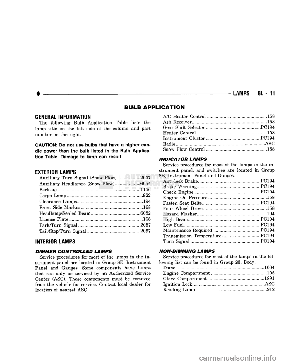
BULB
APPLICATION
GENERAL
INFORMATION
The following Bulb Application Table lists
the
lamp title
on the
left side
of the
column
and
part
number
on the
right.
CAUTION:
Do not use
bulbs
that
have
a
higher
can
dle power than
the
bulb
listed
in the
Bulb
Applica
tion Table.
Damage
to
lamp
can
result.
EXTERIOR LAMPS
Auxiliary Turn Signal (Snow Plow) 2057
Auxiliary Headlamps (Snow Plow) .6054
Back-up....................... .......1156 Cargo Lamp..
922
Clearance Lamps
194
Front Side Marker
168
Headlamp/Sealed Beam .6052
License Plate
168
Park/Turn Signal 2057
TaiyStop/Turn Signal ...2057
INTERIOR LAMPS
DIMMER CONTROLLED LAMPS Service procedures
for
most
of the
lamps
in the in
strument panel
are
located
in
Group
8E,
Instrument
Panel
and
Gauges. Some components have lamps
that
can
only
be
serviced
by an
Authorized Service Center (ASC). These components must
be
removed
from
the
vehicle
for
service. Contact local dealer
for
location
of
nearest
ASC.
A/C Heater Control
158
Ash Receiver
..158
Gear Shift Selector...........................................PC194
Heater Control
158
Instrument Cluster.. PC 194
Radio
ASC
Snow Plow Control
.158
INDICATOR LAMPS Service procedures
for
most
of the
lamps
in the in
strument panel,
and
switches
are
located
in
Group
8E,
Instrument Panel
and
Gauges. Anti-lock Brake PC194
Brake Warning PC194 Check Engine PC194
Engine
Oil
Pressure
158
Fasten Seat Belts.. PC 194 Four Wheel Drive ....158
Hazard Flasher
194
High Beam PC194
Low Fuel....... JPC194
Maintenance Required PC 194
Transmission Temperature ..PC 194 Turn Signal PC194
NON-DIMMING LAMPS Service procedures
for
most
of the
lamps
in the
fol
lowing list
can be
found
in
Group
23,
Body.
Dome
1004
Engine Compartment ...105 Glove Compartment....
1891
Ignition Lock
ASC
Reading Lamp
912
Page 456 of 1502
•
REAR
WINDOW DEFOGGER
8N - 1
REAR
WINDOW
DEFOGGER
CONTENTS
page
REPAIR
PROCEDURES (GRID LINES,
TERMINALS,
AND
PIGTAILS)
3
GENERAL
INFORMATION
The electrically heated rear window defogger
is
available
on
Ramcharger with sunscreen glass only. The system consists
of a
rear window with
two
ver
tical
bus
bars
and a
series
of
electrically connected
grid lines baked
on the
inside surface. Circuit protection
for the
heated grid circuit
is
pro
vided
by a 18
gauge fusible link wire located
in the
engine compartment.
The
relay circuit
is
protected
by
a 20 amp
fuse, located
in the
fuse block. When
the
rear window defogger switch
is
placed
in
the
ON
position, current
is
directed
to
rear window
grid lines.
The
heated grid lines
in
turn heat
the
rear window
to
clear
the
surface
of fog or
snow.
CAUTION;
Grid lines
can be
damaged
or
scraped
off
with
sharp instruments. Care should
be
taken
in
page
SERVICE
PROCEDURES
4
TEST
PROCEDURES
1
cleaning
the
glass
or
removing foreign materials,
decals
or
stickers. Normal
glass
cleaning solvents
or
hot
water
used
with
rags
or
toweling
is
recom mended.
SYSTEM
DESCRIPTION CONTROL
SWITCH/TIMER
RELAY MODULE
The control switch
and
timer relay
are
integrated
into
a
single panel mounted assembly. Actuating
the
switch energizes
the
electronic timing circuit. This
allows current
to
flow through
the
grid system
for
approximately
10
minutes,
or
until either
the
control
switch
or
ignition
is
turned
off. An
indicating lamp
illuminates
a
lens inlaid
in the
control switch.
TEST PROCEDURES
SYSTEM
TEST
Electrically heated rear window defogger operation
can
be
checked in-vehicle
in the
following manner: (1) Turn
the
ignition
ON.
(2) Turn rear window defogger control switch
ON.
(3) Monitor vehicle voltmeter. With
the
control
switch
ON, a
distinct needle deflection should
be
noted. (4)
The
rear window defogger operation
can be
checked
by
feeling
the
glass.
A
distinct difference
in
temperature between
the
grid lines
and
adjacent clear glass
can be
detected
in 3 to 4
minutes
of
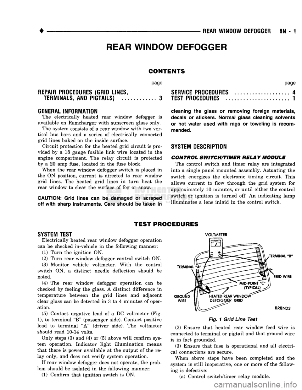
operation. (5) Contact negative lead
of a DC
voltmeter
(Fig.
1),
to
terminal
"B"
(passenger side). Contact positive
lead
to
terminal
"A"
(driver side).
The
voltmeter
should read
10-14
volts. Only steps
(3) and (4) or (5)
above will confirm sys
tem operation. Indicator light illumination means
that there
is
power available
at the
output
of the re
lay only,
and
does
not
verify system operation.
If rear window defogger does
not
operate,
the
prob
lem should
be
isolated
in the
following manner:
(1) Confirm that ignition switch
is ON.
VOLTMETER
Fig.
1
Grid
Line
Test (2) Ensure that heated rear window feed wire
is
connected
to
terminal
or
pigtail
and
that ground wire
is
in
fact grounded.
(3) Ensure that fuse
is
operational
and all
electri
cal connections
are
secure.
When above steps have been completed
and the
system
is
still inoperative,
one or
more
of the
follow
ing
is
defective:
(a) Control switch/timer relay module.
Page 469 of 1502
8T - 2
POWER MIRRORS
•
MIRROR
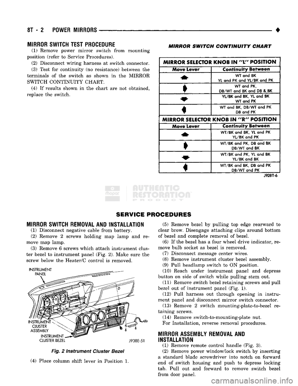
SWITCH TEST PROCEDURE
(1) Remove power mirror switch from mounting
position (refer to Service Procedures). (2) Disconnect wiring harness at switch connector.
(3) Test for continuity (no resistance) between the
terminals of the switch as shown in the MIRROR SWITCH CONTINUITY CHART. (4) If results shown in the chart are not obtained,
replace the switch.
MIRROR
SWITCH
CONTINUITY
CHART
MIRROR SELECTOR KNOB
IN
"L"
POSITION Move
Lever Continuity Between
WT
and BK
YL
and
PK
and
YL/BK
and PK
WT
and
PK,
DB/WT
and
BK
and
DB
&
BK
YL/BK
and
BK, YL
and
BK WT and PK
WT
and
BK, DB/WT
and PK
DB
and
PK
MIRROR SELECTOR KNOB
IN "R"
POSITION Move
Lever Continuity Between
WT/BK
and
BK,
YL and PK
YL/BK
and PK
•
WT/BK
and
PK, DB
and
BK
DB/WT
and
BK
WT/BK
and
PK, YL
and
BK
YL/BK
and
BK
«
WT/BK
and
BK, DB
and PK
DB/WT
and PK
J928T-6
SERVICE PROCEDURES
MIRROR
SWITCH REMOVAL AND INSTALLATION
(1) Disconnect negative cable from battery.
(2) Remove 2 screws holding map lamp and re
move map lamp. (3) Remove 6 screws which attach instrument clus
ter bezel to instrument panel (Fig. 2). Make sure the screw below the Heater/C control is removed.
INSTRUMENT
CLUSTER
BEZEL
J938E-51
Fig.
2 Instrument
Cluster
Bezel
(4) Place column shift lever in Position 1. (5) Remove bezel by pulling top edge rearward to
clear brow. Disengage attaching clips around bottom
of bezel and complete removal of bezel.
(6) If the bezel has a four wheel drive indicator, re
move bulb socket as bezel is removed. (7) Disconnect message center wires.
(8) Remove instrument cluster bezel assembly.
(9) Pull headlamp switch to ON position.
(10) Reach under instrument panel and depress
button on side of switch while pulling stem out.
(11) Remove switch bezel retaining screws and pull
bezel out of instrument panel (Fig. 1). (12) Pull harness out through opening in instru
ment panel and disconnect mirror switch connector.
(13) Remove 2 switch mounting-plate-to-bezel re
taining screws.
(14) Remove switch-to-mounting-plate nut.
For Installation, reverse removal procedures.
MIRROR
ASSEMBLY
REMOVAL
AND
INSTALLATION
(1) Remove remote control handle (Fig. 3).
(2) Remove power window/lock switch by inserting
a standard blade screwdriver into notch on forward
end of switch housing and push to depress locking
tab.
Pull out and forward to remove switch bezel
from door panel.
Page 514 of 1502
WIRING
DIAGRAMS
8W - 39
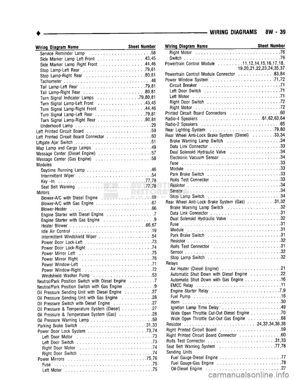
Wiring
Diagram
Name
Sheet
Number
Service Reminder Lamp .58
Side
Marker Lamp
Left
Front
43,45
Side
Marker Lamp Right
Front
. .44,46
Stop
Lamp-Left
Rear 79,81 Stop Lamp-Right Rear 80,81
Tachometer
.48
Tail
Lamp-Left
Rear .79,81
Tail
Lamp-Right Rear 80,81
Turn
Signal
Indicator
Lamps .79,80,81
Turn
Signal
Lamp-Left
Front
43,45
Turn
Signal Lamp-Right
Front
44,46
Turn
Signal
Lamp-Left
Rear .79,81
Turn
Signal Lamp-Right Rear 80,81
Underhood Lamp 29
Left
Printed
Circuit
Board .59
Left
Printed
Circuit
Board Connector 60
Liftgate
Ajar
Switch
51
Map
Lamp and Cargo Lamps .49
Message
Center
(Diesel Engine) 57
Message
Center
(Gas Engine) .58
Modules
Daytime
Running Lamp . .46
Intermittent
Wiper
.54
Key
-In
77,78
Seat
Belt
Warning 77,78
Motors Blower-A/C
with
Diesel Engine .69
Blower-A/C
with
Gas Engine 67
Blower-Heater
.66
Engine
Starter
with
Diesel Engine . .7 Engine
Starter
with
Gas Engine 9
Heater
Blower
66,67
Idle
Air
Control
............... ........
.19
Intermittent
Windshield
Wiper
54
Power Door
Lock-Left
.73
Power Door Lock-Right 74
Power
Mirror
Left
75
Power
Mirror
Right .76 Power
Window-Left
71
Power Window-Right .72
Windshield Washer Pump 53
Neutral/Park
Position
Switch
with
Diesel Engine 7
Neutral/Park
Position
Switch
with
Gas Engine 9
Oil Pressure Sending
Unit
with
Diesel Engine 27
Oil Pressure Sending
Unit
with
Gas Engine 28 Oil Pressure
Switch
with
Diesel Engine 27
Oil Pressure &
Temperature
System (Diesel) 27 Oil Pressure &
Temperature
System (Gas) . 28
Oil Pressure Warning Lamp • -59 Parking Brake
Switch
.31,33 Power Door Lock System . . 73,74
Left
Door Motor . .73
Left
Door
Switch
. 73
Right Door Motor . -74 Right Door
Switch
74
Power
Mirrors
75,76
Fuse
75
Left
Motor 75
Wiring
Diagram
Name
Sheet
Number
Right Motor 76
Switch
76
Powertrain
Control
Module
........
.11,12,14,15,16,17,18,
19,20,21,22,23,24,35,37
Powertrain
Control
Module Connector .83,84
Power Window System 71,72
Circuit
Breaker 71
Left
Door
Switch
71
Left
Motor 71 Right Door
Switch
72
Right Motor 72
Printed
Circuit
Board Connectors 60
Radio-4 Speakers 61,62,63,64
Radio-2 Speakers 65
Rear
Lighting
System 79,80
Rear
Wheel
Anti-Lock
Brake System (Diesel) 33,34 Brake Warning Lamp
Switch
.34 Data
Link
Connector 33
Dual Solenoid
Hydraulic
Valve 34
Electronic
Vacuum
Sensor
34
Fuse
.33 Module 33 Park Brake
Switch
33
Rolls Test Connector .33 Resistor .34
Sensor
. .34 Stop Lamp
Switch
. .34
Rear
Wheel
Anti-Lock
Brake System (Gas) . .31,32 Brake Warning Lamp
Switch
.32
Data
Link
Connector .31 Dual Solenoid
Hydraulic
Valve 32
Fuse
31
Module 31 Park Brake
Switch
31
Resistor 32 Rolls Test Connector 31
Sensor
32
Stop Lamp
Switch
32
Relays
Air
Heater
(Diesel Engine) .21
Automatic
Shut Down
with
Diesel Engine 22
Automatic
Shut Down
with
Gas Engine 16
EMCC
Relay 11 Engine
Starter
Relay .7,9
Fuel Pump 16
Horn 30
Ignition
Lamp
Time
Delay 49
Wide Open
Throttle
Cut-Out Diesel Engine 70
Wide Open
Throttle
Cut-Out Gas Engine 68
Resistor 24,32,34,36,38
Right
Printed
Circuit
Board 59 Right
Printed
Circuit
Board Connector 60 Rolls Test Connector .31,33
Seat
Belt
Warning System 77,78
Sending
Units
Fuel Gauge-Diesel Engine 77 Fuel
Gauge-Gas
Engine 78
Oil-Diesel Engine 27
Page 518 of 1502
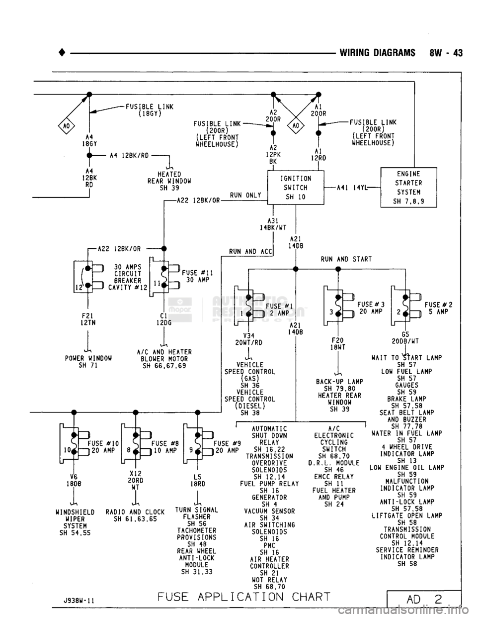
WIRING
DIAGRAMS
8W - 43
FUSIBLE
LINK
(18GY)
12BK/RD
FUSIBLE
LINK
(200R)
(LEFT
FRONT
WHEELHOUSE) HEATED
REAR
WINDOW
SH
39
FUSIBLE
LINK
(200R)
(LEFT
FRONT
WHEELHOUSE)
I—A22
12BK/0R
IT
1
30
AMPS
J CIRCUIT
,—h BREAKER —P CAVITY
#12
-A22
12BK/0R-
RUN ONLY
IGNITION
SWITCH
SH
10
A31
14BK/WT
RUN
AND ACC
F21
12TN
POWER WINDOW
SH
71
FUSE
#11
30 AMP
CI
12DG
A/C
AND
HEATER BLOWER MOTOR
SH
66.67.69
S
FUSE
#10
10*ZJ20
AMP
O
FUSE
#8
310 AMP
-A41
14YL-
ENGINE
STARTER
SYSTEM
SH
7.8.9
A21
14DB
FUSE
#1
3
2 AMP
RUN
AND
START
V34
20WT/RD
A2I
14DB
VEHICLE
SPEED
CONTROL (GAS)
SH
36
VEHICLE
SPEED
CONTROL (DIESEL)
SH
38
FUSE
#3
20 AMP
F20
18WT
BACK-UP
LAMP
SH
79.80
HEATER REAR WINDOW
SH
39
G5
20DB/WT
TO
4tART
D
FUSE
# 2
3
5 AMP
LAMP LOW
FUSE
#9
120 AMP
V6
18DB
WINDSHIELD WIPER
SYSTEM
SH
54.55
RADIO
AND
CLOCK
SH
61.63.65
L5
18RD
i
TURN SIGNAL FLASHER
SH
56
TACHOMETER
PROVISIONS
SH
48
REAR
WHEEL ANTI-LOCK
MODULE
SH
31.33
AUTOMATIC
SHUT DOWN
RELAY
SH
16.22
TRANSMISSION
OVERDRIVE
SOLENOIDS
SH
12.14
FUEL PUMP RELAY
SH
16
GENERATOR
SH
4
VACUUM SENSOR
SH
34
AIR SWITCHING
SOLENOIDS
SH
16
PMC
SH
16
AIR HEATER CONTROLLER
SH
21
WOT RELAY
SH
68.70
A/C
ELECTRONIC CYCLING SWITCH
SH
68.70
3.R.L.
MODULE
SH
46
EMCC
RELAY
SH
11
FUEL HEATER AND PUMP
SH
24
WAIT
TO
START
SH
57
FUEL LAMP
SH
57
GAUGES
SH
59
BRAKE
LAMP
SH
57.58
SEAT
BELT LAMP AND BUZZER
SH
77 78
WATER
IN
FUEL LAMP
SH
57
4
WHEEL DRIVE
INDICATOR LAMP
SH
13
LOW ENGINE
OIL
LAMP
SH
59
MALFUNCTION
INDICATOR LAMP
SH
59
ANTI-LOCK LAMP
SH
57 58
LIFTGATE OPEN LAMP
SH
58
TRANSMISSION
CONTROL MODULE
SH
12.14
SERVICE
REMINDER INDICATOR LAMP
SH
58
J938W-11
FUSE
APPLICATION
CHART
AD
2
Page 535 of 1502

8W - 60
WIRING
DIAGRAMS
IDLE AIR
CONTROL MOTOR
GRAY
nrrrrnrj
pnrn (ON THROTTLE
BODY) 4 3 2 1
K59
18VT
BK
59
IAC TO
SPLICE
(SEE
SH 9)
T
T41
18BR YL K40
18BR WT
i K60
18YL
BK
K39
18GY
RD
.1 n las
2 3 ^ 4
•G3 20BK/PK—1 TO PRINTED
CIRCUIT BOARD CONNECTOR
(SEE
SH 60) G7
20WT
OR TO DAYTIME
RUNNING LAMP MODULE
(CANADA ONLY)
(SEE
SH 46) G7
20WT
OR G7 <8>-
20WT/0R~H>
G3
20BK
PK
38 13 G7
20WT
OR 43
TO
MESSAGE
CENTER
SERVICE
REMINDER
INDICATOR
(SEE
SH 58)
G24
22 GY
PK
42
G3
20BK
PK
•-{ENGf-
TO
CHARGING
SYSTEM
(SEE
SH 4)
T
K20
18DG 'T
G24
20GY
PK
33
;HENG}~
24
—[ETTGI—
G7
20WT/0R
G3
20BK
PK
G24
20GY
PK
30
PARK/
NEUTRAL SWITCH 40 60 39 20 32
IAC IAC IAC GENERATOR MIL FIELD
POWERTRAIN CONTROL MODULE II (PCM II] 56
SRI
CONNECTOR (SEE SH 84)
(LEFT
FENDER SIDE SHIELD)
AD
19
IGNITION
SYSTEM
GAS
MFI ENGINE
J938W-11
Page 574 of 1502

•
WIRING
DIAGRAMS
8W - 99
DIODE-
BRAKE LAMP
GATE OPEN LAMP
SERVICE REMINDER INDICATOR LAMP
REAR WHEEL
ANT1-LOCK LAMP
TO
TRANSMISSION
OVERDRIVE
CONTROL
SWITCH (DIESEL ONLY
(SEE
SH 14)
I
I
I
I
G5
20DB WT TO FOUR
WHEEL DRIVE
INDICATOR LAMP
(SEE
SH 13)
i ,
-BLACK
G5 20DB/WT
TO RIGHT
PRINTED CIRCUIT
BOARD
CONNECTOR
(SEE
SH 60)
TO
TRANSMISSION
OVERDRIVE
SWITCH
(SEE
SH 12)
(GAS
ONLY)
GRAY
G5 20DB/WT Gil 20WT/BK
SEE
SH 10)
Gil 20WT/BK~
B102 180R
BLACK
TO IGNITION SWITCH GROUND
TO REAR
WHEEL ANTI-LOCK MODULE
(SEE
SH 31)
TO
COMBINED
BUZZER
(SEE
SH
77,78)
G24 22GY/PK SERVICE REMINDER
INDICATOR
(SEE SH 19)
G78 20TN/BK GATE OPEN LAMP
(SEE
SH 51)
G9 20GY/BK
TO
REAR WHEEL ANTI-LOCK
MODULE
(SEE SH 31)
G9 20GY/BK
TO
BRAKE LAMP WARNING
SWITCH
(SEE SH 31)
TO LEFT
PRINTED CIRCUIT
BOARD
CONNECTOR
(SEE
SH 60)
A21
14DB-
FUSE
#2 (5 AMP)
TO IGNITION
SWITCH
(SEE
SH 10)
J938W-11
MESSAGE
CENTER
(GAS)
AD
58
Page 600 of 1502
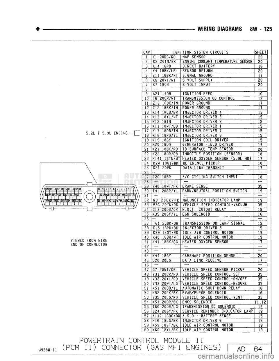
WIRING
DIAGRAMS 8W - 125
5.2L £ 5.9L ENGINE VIEWED FROM WIRE
END OF CONNECTOR
POWERTRAIN
CON
J938W-H
(PCM II) CONNECTOR
CAV
IGNITION
SYSTEM CIRCUITS SHEET
1
Kl
200G/RD
MAP
SENSOR
20
2"-1 K2
20TN/BK
ENGINE COOLANT TEMPERATURE SENSOR
20
3 A14
IBRD
DIRECT BATTERY
16
4 K4 18BK/LB
SENSOR
RETURN
20
5 Zll
16BK/WT
SIGNAL
GROUND
17
6 K6
20VT/WT
5 VOLT SUPPLY
20
7
K7
180R 8 VOLT INPUT
20
8 —
—
9 A21 14DB IGNITION FEED
16
10 T6
200R/WT
TRANSMISSION
OD CONTROL
12
11 Z12 18BK/TN POWER GROUND
17
12 Z12 18BK/TN POWER GROUND
17
13 |Kl4 18LB/BR
INJECTOR DRIVER 4
15
14 K13
18YL/WT
INJECTOR DRIVER 3
15
15 K12 18TN INJECTOR DRIVER 2
15
16
17" Kl1
18WT/DB
INJECTOR DRIVER 1
15
16
17"
K17
18DB/TN
INJECTOR DRIVER 7
15
18 K18
18RD/YL
INJECTOR DRIVER 8
15
19 K19 18GY IGNITION COIL DRIVER
15
20 K20 18DG GENERATOR FIELD DRIVER
19
21 K21
18BK/RD
TB SURFACE TEMP SENSOR
20
22 K22
180R/DB
THROTTLE POSITION (SENSOR)
18
23 K141
18TN/WT
HEATED OXYGEN SENSOR (5.9L HD)
17
24 K24 18GY/BK
REFERENCE
PICKUP
18
25 021
20PK
DATA LINK TRANSMIT
17
26 —
—
27 C20 18BR
A/C
CYCLING SWITCH INPUT
18
28 — _
29 V40
18WT/PK
BRAKE
SENSE
35
30 T41
20BR/YL
PARK/NEUTRAL POSITION SWITCH
19
31 —
—
32 G3
20BK/PK
MALUNCTION INDICATOR LAMP
19
33 V36
20TM/RD
VEHICLE SPEED CONTROL-VACUUM
35
34 C13 20DB/OR W.O.T. CUTOUT RELAY
18
35 K35 20GY/YL
EGR
SOLENOID
16
36 —
— —
37 TBI 20BK/0R
TRANSMISSION
OD LAMP SIGNAL
12
38 K15
18PK/BK
INJECTOR DRIVER 5
15
39
"40 K39 18GY/RD
IDLE AIR CONTROL MOTOR
19
39
"40 K40 18BR/WT IDLE AIR CONTROL MOTOR
19
41 K41
18BK/DG
HEATED OXYGEN SENSOR
17
42
43 —
—
42
43 —
—
—
44 K44 18GY CAMSHAFT POSITION
SENSE
20
45 020 20LG
DATA LINK RECEIVE
17
46 —
— —
47 G7
20WT/OR
VEHICLE SPEED SENSOR PICKUP
20
48 V31
20BR/RD
VEHICLE SPEED CONTROL-SET
35
49 V32
20YL/RD
VEHICLE SPEED CONTROL-ON/OFF
35
50 Y33
20WT/LG
VEHICLE SPEED CONTROL-RESUME
35
51 K51 20DB/YL AUTOMATIC SHUT-DOWN RELAY
16
52 K52
20PK/BK
EVAP/PURGE
SOLENOID
16
53 V35
20LG/RD
VEHICLE SPEED CONTROL-VENT
35
54 K54
200R/BK
EMCC
SOLENOID
11.12
55 T60
200R/LG
TRANSMISSION
OD SOLENOID
12
5G G24
20GY/PK
SERVICE
REMINDER INDICATOR LAMP
13
57 A142 16DG/0R
A.S.D.-
BATTERY
SENSE
15
58 K16 18LG/BK INJECTOR DRIVER 6
15
59 K59 18VT/BK IDLE AIR CONTROL MOTOR
19
60 K60 18YL/BK IDLE AIR CONTROL MOTOR
19
TROL
MODULE II
(GAS
MFI ENGINES) AD 84