1993 DODGE TRUCK service indicator
[x] Cancel search: service indicatorPage 342 of 1502
• BATTERY/STARTER/GENERATOR
SERVICE
8B - 1
CONTENTS
page page
BATTERY
SERVICE
PROCEDURES
1 SPECIFICATIONS 9
GENERATOR
SERVICE
6 STARTER
SERVICE
PROCEDURES
4
BATTERY SERVICE PROCEDURES
GENERAL
INFORMATION This section will cover the Battery service, re
moval, and installation procedures only. For diagnos
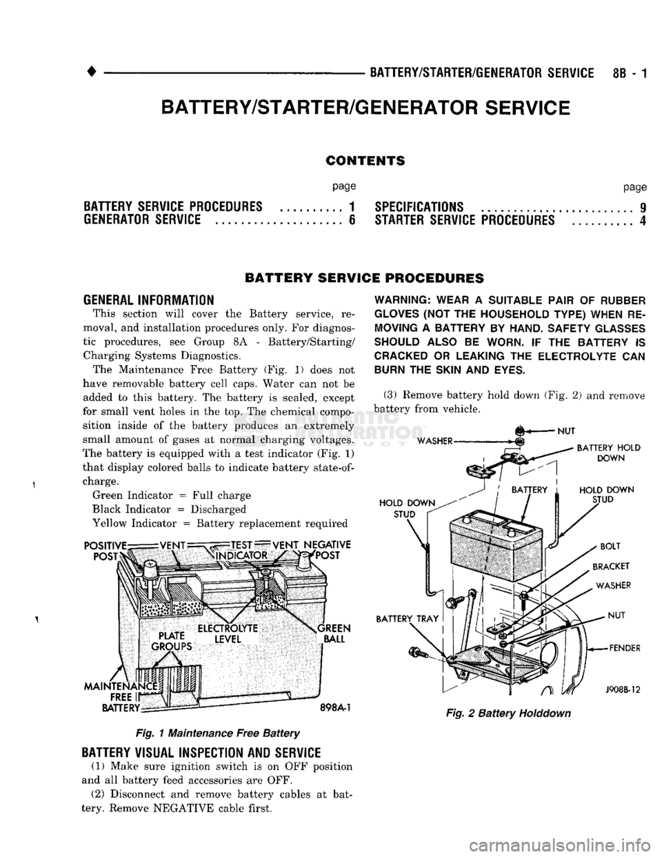
tic procedures, see Group 8A - Battery/Starting/ Charging Systems Diagnostics. The Maintenance Free Battery (Fig. 1) does not
have removable battery cell caps. Water can not be added to this battery. The battery is sealed, except
for small vent holes in the top. The chemical compo sition inside of the battery produces an extremely
small amount of gases at normal charging voltages.
The battery is equipped with a test indicator (Fig. 1)
that display colored balls to indicate battery
state-of-
charge. Green Indicator = Full charge
Black Indicator = Discharged
Yellow Indicator = Battery replacement required Fig. 1 Maintenance Free Battery
BATTERY
VISUAL INSPECTION AND
SERVICE
(1) Make sure ignition switch is on OFF position
and all battery feed accessories are OFF. (2) Disconnect and remove battery cables at bat
tery. Remove NEGATIVE cable first.
WARNING: WEAR
A
SUITABLE PAIR
OF
RUBBER
GLOVES
(NOT THE
HOUSEHOLD TYPE) WHEN
RE
MOVING
A
BATTERY
BY
HAND. SAFETY
GLASSES
SHOULD ALSO
BE
WORN.
IF THE
BATTERY
IS
CRACKED
OR
LEAKING
THE
ELECTROLYTE
CAN
BURN
THE
SKIN
AND
EYES.
(3) Remove battery hold down (Fig. 2) and remove
battery from vehicle. Fig. 2 Battery
Holddown
BATTERY/STARTER/GENERATOR
SERVICE
Page 343 of 1502
8B
- 2
BATTERY/STARTER/GENERATOR SERVICE
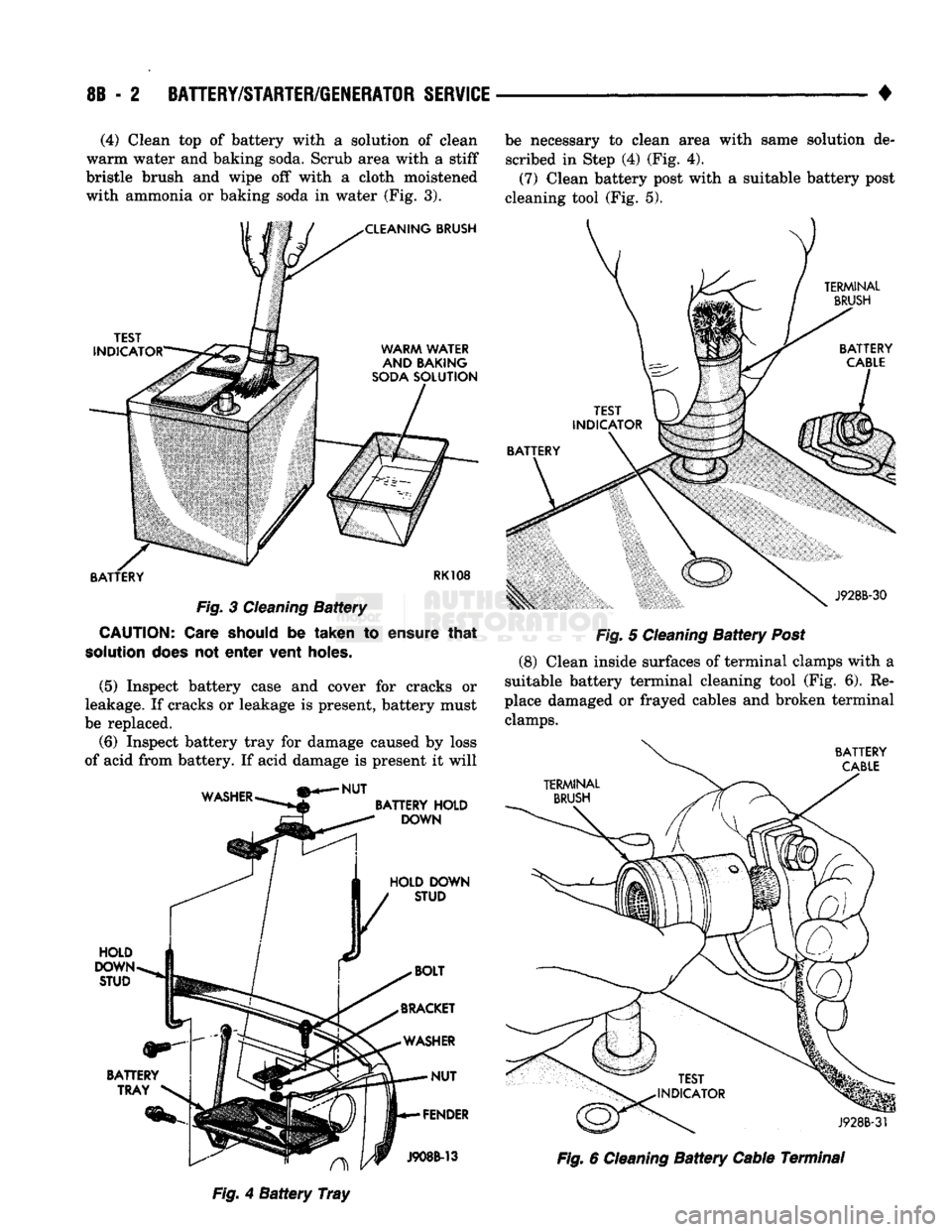
• (4) Clean top of battery with a solution of clean
warm water and baking soda. Scrub area with a stiff
bristle brush and wipe off with a cloth moistened
with ammonia or baking soda in water (Fig. 3). be necessary to clean area with same solution de
scribed in Step (4) (Fig. 4).
(7) Clean battery post with a suitable battery post
cleaning tool (Fig. 5).
TERMINAL
BRUSH
TEST
INDICATOR
BATTERY Fig.
3
Cleaning
Battery
CAUTION:
Care should
be
taken
to
ensure
that
solution
does
not
enter
vent holes.
(5) Inspect battery case and cover for cracks or
leakage. If cracks or leakage is present, battery must
be replaced.
(6) Inspect battery tray for damage caused by loss
of acid from battery. If acid damage is present it will J928B-30
Fig.
5
Cleaning
Battery
Post
(8)
Clean inside surfaces of terminal clamps with a
suitable battery terminal cleaning tool (Fig. 6). Re
place damaged or frayed cables and broken terminal clamps.
BATTERY
CABLE
WASHER
NUT
BATTERY
HOLD
DOWN
HOLD DOWN STUD HOLD
DOWN
STUD
BATTERY TRAY
J928B-3f A
Fig.
4
Battery
Tray
J908B-13
Fig.
6
Cleaning
Battery
Cable Terminal
Page 382 of 1502
• • ^ ^ ^ INSTRUMENT PANEL AND GAUGES 8E - 1
CONTENTS
page
CLUSTER AND GAUGE SERVICE PROCEDURES . 12
CLUSTER AND GAUGE TEST PROCEDURES .. i
GENERAL INFORMATION . 1
page
MESSAGE CENTER-DIESEL ENGINE ........ 4
MESSAGE CENTER-GAS ENGINE .......... 3
SWITCH
AND PANEL COMPONENT SERVICE . 16
GENERAL
INFORMATION
INDEX
page
Generator
Indicating
System
2
Distance
Sensor
2
Electronic
Digital
Clock
3
Fuel
Level
Indicating
System
1
page
Malfunction
Indicator
(Check
Engine)
3
Oil
Pressure
Warning
Lamp
................. 2
Speedometer/Odometer
System
2
Temperature
and Oil
Indicating
System
......... 2
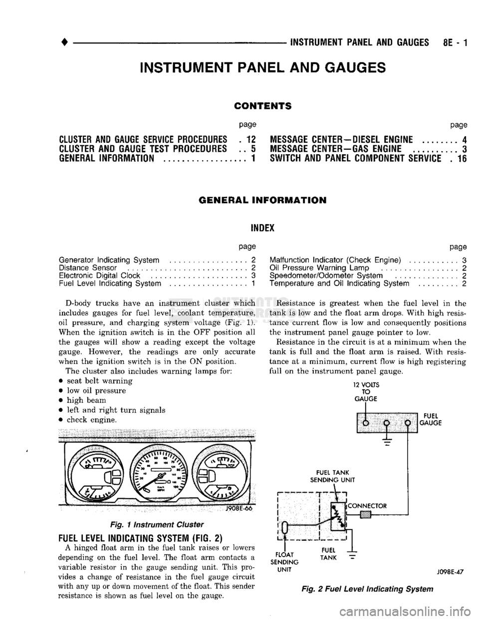
D-body trucks have an instrument cluster which
includes gauges for fuel level, coolant temperature,
oil pressure, and charging system voltage (Fig. 1).
When the ignition switch is in the OFF position all
the gauges will show a reading except the voltage gauge. However, the readings are only accurate
when the ignition switch is in the ON position.
The cluster also includes warning lamps for:
• seat belt warning
• low oil pressure
• high beam
• left and right turn signals
• check engine. J908E-66
Fig.
11nstrument
Cluster
FUEL LEVEL INDICATING SYSTEM (FIG. 2)
A hinged float arm in the fuel tank raises or lowers
depending on the fuel level. The float arm contacts a
variable resistor in the gauge sending unit. This pro
vides a change of resistance in the fuel gauge circuit
with any up or down movement of the float. This sender
resistance is shown as fuel level on the gauge. Resistance is greatest when the fuel level in the
tank is low and the float arm drops. With high resis
tance current flow is low and consequently positions
the instrument panel gauge pointer to low.
Resistance in the circuit is at a minimum when the
tank is full and the float arm is raised. With resis
tance at a minimum, current flow is high registering
full on the instrument panel gauge.
12
VOLTS
TO
GAUGE
IP
FUEL
TANK
SENDING
UNIT
FLOAT
SENDING
UNIT
1:
1
j
^
fCONNECTOR
!g|yj-»—
FUEL
GAUGE
FUEL
TANK
J098E-47
Fig.
2
Fuel
Level
Indicating
System
INSTRUMENT PANEL AND GAUGES
Page 384 of 1502
•
INSTRUMENT PANEL
AND
GAUGES
8E - 3
MALFUNCTION INDICATOR (CHECK ENGINE)
Fig.
5
Distance Sensor
If
the
input from
one of the
following sensors fails
an internal Powertrain Control Module
(PCM)
self
check,
the PCM
turns
on the
Check Engine Lamp. The
PCM
then substitutes
a
modified signal
in
place
of
the one
that failed until
a
repair
is
made:
• Manifold Absolute Pressure (MAP) Sensor
• Throttle Position Sensor
• Coolant Temperature Sensor
• Battery Voltage Sense
• Battery Voltage
Too
High
Refer
to the
appropriate Powertrain Diagnostic
Test Procedures manual
for
further information.
ELECTRONIC DIGITAL CLOCK
The electronic digital clock
is in the
radio.
The
clock
and
radio each
use the
display panel built into
the radio.
A
digital readout indicates
the
time
in
hours
and
minutes whenever
the
ignition switch
is in
the
ON or ACC
position. When
the
ignition switch
is in the OFF
position
or
when
the
radio frequency
is
being displayed, time keeping
is
accurately maintained. The procedure
for
setting
the
clock varies slightly
with each radio.
The
correct procedure
is
described under
the
individual radio operating instructions
re
ferred
to in the
Owner Manual supplied with
the ve
hicle.
MESSAGE CENTER—GAS ENGINE
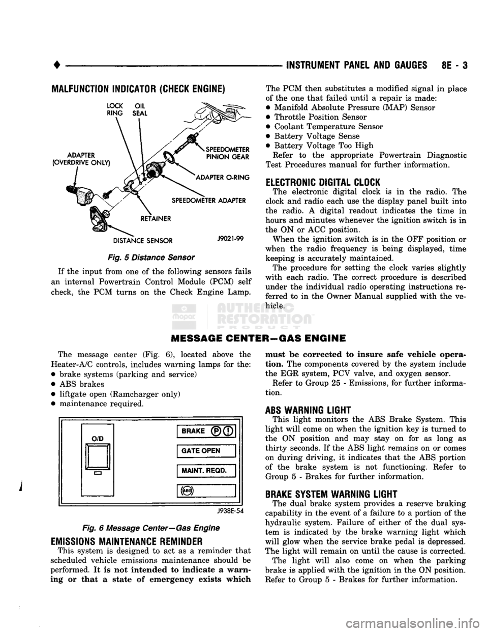
The message center
(Fig. 6),
located above
the
Heater-A/C controls, includes warning lamps
for the:
• brake systems (parking
and
service)
•
ABS
brakes • liftgate open (Ramcharger only)
• maintenance required.
O/D
BRAKE
(P)(7
GATE OPEN
MAINT
REQD.
J938E-54
Fig.
6
Message Center—Gas Engine
EMISSIONS
MAINTENANCE REMINDER
This system
is
designed
to act as a
reminder that
scheduled vehicle emissions maintenance should
be
performed.
It is not
intended
to
indicate
a
warn
ing
or
that
a
state
of
emergency exists which must
be
corrected
to
insure safe vehicle opera
tion.
The
components covered
by the
system include
the
EGR
system,
PCV
valve,
and
oxygen sensor. Refer
to
Group
25 -
Emissions,
for
further informa
tion.
ABS
WARNING
LIGHT
This light monitors
the ABS
Brake System. This
light will come
on
when
the
ignition
key is
turned
to
the
ON
position
and may
stay
on for as
long
as
thirty seconds.
If the ABS
light remains
on or
comes on during driving,
it
indicates that
the ABS
portion
of
the
brake system
is not
functioning. Refer
to
Group
5 -
Brakes
for
further information.
BRAKE
SYSTEM WARNING
LIGHT
The dual brake system provides
a
reserve braking
capability
in the
event
of a
failure
to a
portion
of the
hydraulic system. Failure
of
either
of the
dual sys
tem
is
indicated
by the
brake warning light which
will glow when
the
service brake pedal
is
depressed.
The light will remain
on
until
the
cause
is
corrected. The light will also come
on
when
the
parking
brake
is
applied with
the
ignition
in the ON
position.
Refer
to
Group
5 -
Brakes
for
further information.
Page 385 of 1502
8E
- 4
INSTRUMENT PANEL
AND
GAUGES
•
MESSAGE CENTER—DIESEL
ENGINE
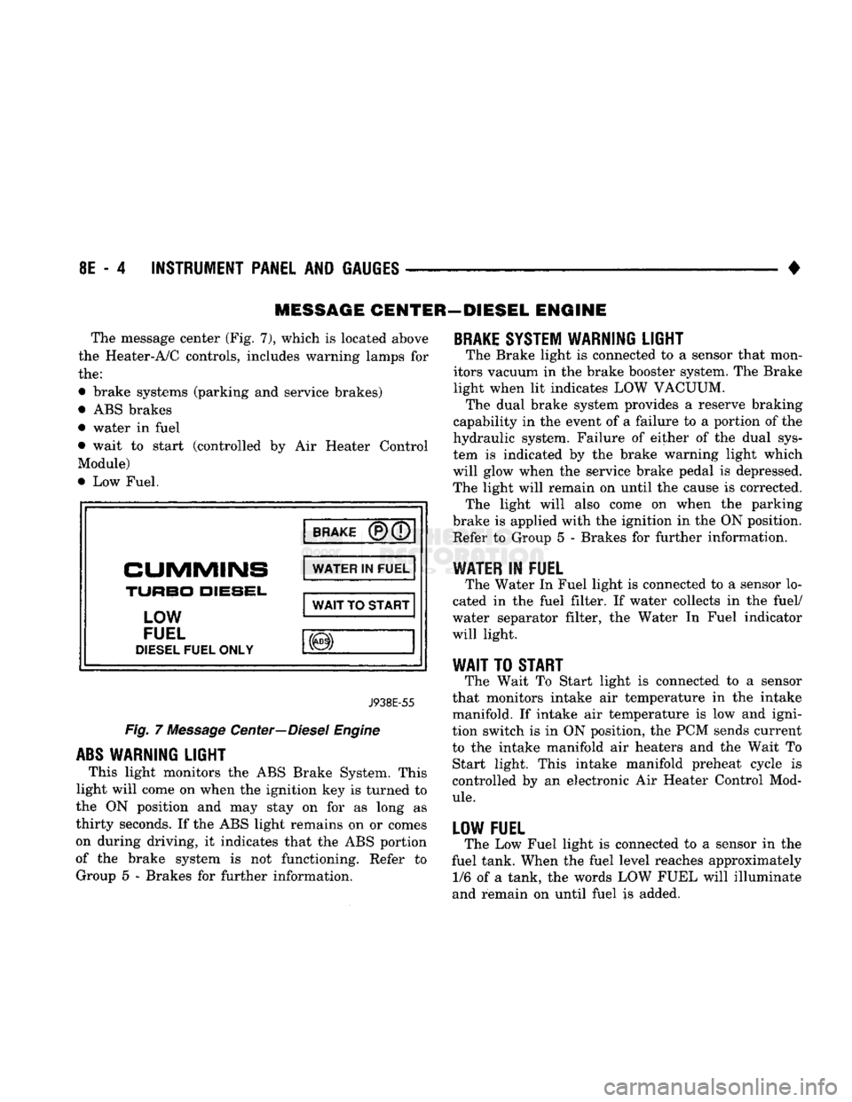
The message center (Fig. 7), which
is
located above
the Heater-A/C controls, includes warning lamps
for
the:
• brake systems (parking
and
service brakes)
• ABS brakes
• water
in
fuel
• wait
to
start (controlled
by Air
Heater Control
Module)
• Low Fuel.
BRAKE
CUMMINS
TURBO
DIESEL,
LOW
FUEL
DIESEL
FUEL ONLY WATER
IN
FUEL
WAIT
TO
START
J938E-55
Fig.
7
Message Center—Diesel Engine
ABS
WARNING LIGHT
This light monitors
the
ABS Brake System. This
light will come
on
when the ignition key
is
turned
to
the
ON
position
and may
stay
on for as
long
as
thirty seconds.
If
the ABS light remains
on or
comes
on during driving,
it
indicates that
the
ABS portion
of
the
brake system
is not
functioning. Refer
to
Group
5 -
Brakes
for
further information.
BRAKE
SYSTEM WARNING LIGHT
The Brake light
is
connected
to a
sensor that mon
itors vacuum
in
the brake booster system. The Brake
light when
lit
indicates LOW VACUUM. The dual brake system provides
a
reserve braking
capability
in
the event
of a
failure
to a
portion
of
the
hydraulic system. Failure
of
either
of the
dual sys
tem
is
indicated
by the
brake warning light which
will glow when
the
service brake pedal
is
depressed.
The light will remain
on
until
the
cause
is
corrected. The light will also come
on
when
the
parking
brake
is
applied with the ignition
in
the ON position. Refer
to
Group
5 -
Brakes
for
further information.
WATER
IN
FUEL
The Water
In
Fuel light
is
connected
to a
sensor lo
cated
in the
fuel filter.
If
water collects
in the
fuel/
water separator filter,
the
Water
In
Fuel indicator
will light.
WAIT
TO
START
The Wait
To
Start light
is
connected
to a
sensor
that monitors intake
air
temperature
in the
intake
manifold.
If
intake
air
temperature
is low and
igni
tion switch
is in
ON position,
the
PCM sends current
to
the
intake manifold
air
heaters
and the
Wait
To
Start light. This intake manifold preheat cycle
is
controlled
by an
electronic
Air
Heater Control Mod
ule.
LOW FUEL
The Low Fuel light
is
connected
to a
sensor
in the
fuel tank. When the fuel level reaches approximately 1/6
of a
tank,
the
words LOW FUEL will illuminate
and remain
on
until fuel
is
added.
Page 393 of 1502
8E
- 12
INSTRUMENT PANEL
AND
GAUGES
•
CLUSTER AND GAUGE
SERVICE
PROCEDURES
INDEX
page
Cluster Bezel
12
Cluster
Mask
and
Lens
12
Fuel Gauge
13
Instrument
Cluster Assembly
12
Lamp Bulb Replacement—Message Center
..... 15
CLUSTER
BEZEL
REMOVAL
(1) Disconnect negative cable from battery.
(2) Tape
or
cover steering column
to
prevent dam
age
to
paint.
(3) Remove
2
screws and remove map lamp.
CAUTION:
Map
lamp must
be
removed
to
prevent
damage
to
instrument panel.
(4) Remove
6
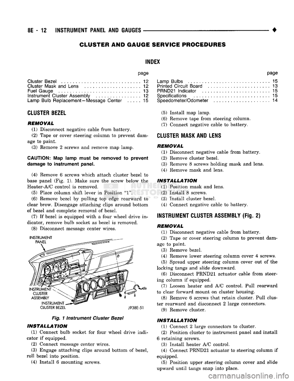
screws which attach cluster bezel
to
base panel (Fig.
1).
Make sure
the
screw below
the
Heater-A/C control
is
removed.
(5)
Place column shift lever
in
Position
"1".
(6) Remove bezel
by
pulling
top
edge rearward
to
clear brow. Disengage attaching clips around bottom
of bezel
and
complete removal
of
bezel.
(7)
If
bezel
is
equipped with
a
four wheel drive
in
dicator, remove bulb socket
as
bezel
is
removed.
(8) Disconnect message center wires.
INSTRUMENT
CLUSTER BEZEL
J938E-51
Fig.
1 instrument
Cluster
Bezel
INSTALLATION
(1) Connect bulb socket
for
four wheel drive indi
cator
if
equipped.
(2)
Connect message center wires.
(3) Engage attaching clips around bottom
of
bezel,
roll bezel into position.
(4) Install
6
mounting screws. page
Lamp Bulbs
. . 15
Printed
Circuit
Board
13
PRND21
Indicator
. 15
Specifications
15
Speedometer/Odometer
14
(5)
Install map lamp.
(6) Remove tape from steering column.
(7) Connect negative cable
to
battery.
CLUSTER
MASK AND LENS REMOVAL
(1) Disconnect negative cable from battery.
(2) Remove cluster bezel.
(3) Remove
8
screws holding mask
and
lens.
(4) Remove mask
and
lens.
INSTALLATION
(1) Position mask
and
lens.
(2) Install
8
screws.
(3) Install cluster bezel.
(4) Connect negative cable
to
battery.
INSTRUMENT CLUSTER ASSEMBLY
(Fig.
2)
REMOVAL
(1) Disconnect negative cable from battery.
(2) Tape
or
cover steering column
to
prevent dam
age
to
paint.
(3) Remove bezel.
(4) Remove lower steering column cover
4
screws.
(5)
Spread upper steering column cover
out of
the
locking tangs
and
slide downward. (6) Disconnect PRND21 actuator cable from steer
ing column
if
equipped.
(7) Loosen heater
and
A/C control. Pull rearward
to clear forward mount
on
cluster housing.
(8) Remove
6
screws that retain cluster. Pull clus
ter rearward
and
disconnect
2
large connectors.
(9) Remove cluster.
INSTALLATION
(1) Connect
2
large connectors
to
cluster.
(2) Position cluster
to
instrument panel and install
6 retaining screws.
(3) Install heater A/C control.
(4) Connect PRND21 actuator
to
steering column
if
equipped.
(5)
Position upper steering column cover
and
slide
upward until tangs snap into place.
Page 397 of 1502
8E - 16 INSTRUMENT PANEL AND GAUGES
• SWITCH AND
PANEL
COMPONENT
SERVICE
INDEX
page
Ash
Tray
20
Cigar
Lighter
........................ 20
Four
Wheel Drive
Indicator
19
Fuse
Block
and
Flashers
................... 19
Glove
Box 21
Heater A/C Control
17
page
Heater Control
16
Hood
Release
19
Illumination
Bulb Replacement
22
Message
Center Module
................... 18
Steering Column Lowering
and
Raising
16
Switches
17
DISCONNECT NEGATIVE CABLE FEOM
BATTERY IN ENGINE COMPAETMENT BE FORE SERVICING INSTRUMENT PANEL.
STEERING COLUMN LOWERING AND RAISING When servicing the instrument panel and the Low
ering and Raising of the steering column is required,
the following is the procedure for doing so: This procedure is not for removing and replac
ing the steering column. Refer to Group - 19 Steering of this manual for the removal and re
placement procedures.
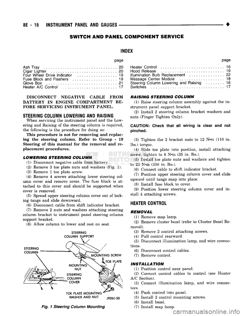
LOWERING STEERING COLUMN
(1) Disconnect negative cable from battery.
(2)
Remove 3 toe plate nuts and washers (Fig. 1).
(3) Remove 1 toe plate screw.
(4) Remove 4 screws attaching lower steering col
umn cover and remove cover. The fuse block is at
tached to this cover and should be supported when cover is removed.
(5) Spread upper steering column cover out of lock
ing tangs and slide downward.
(6)
Disconnect cable from shift indicator bracket.
(7)
Remove 2 nuts and washers attaching steering
column bracket to instrument panel steering column support bracket.
(8)
Allow column to lower and rest on seat.
STEERING
COLUMN SUPPORT
WASHER
AND NUT
Fig.
1 Steering
Column
Mounting
RAISING STEERING COLUMN
(1) Raise steering column assembly against the in
strument panel support bracket. (2) Install 2 steering column bracket washers and
nuts (Finger Tighten Only).
CAUTION:
Check that
all
wiring
is
clear
and not
pinched.
(3) Tighten the 2 bracket nuts to 12 Nnn-(110 in.
lbs.) torque. (4) Slide toe plate into position, install attaching
screw, tighten to 4 N®m (35 in. lbs.).
(5) Install toe plate nuts and washers and tighten
to 23 N*m (200 in. lbs.).
(6)
Connect cable to shift indicator bracket.
(7)
Position upper steering column cover and slide
upward until tangs snap into place.
(8) Install fuse block to cover.
(9)
Position lower steering column cover and in
stall 4 attaching screws.
HEATER CONTROL
REMOVAL
(1) Remove map lamp.
(2) Remove cluster bezel (refer to Cluster Bezel Re
moval). (3) Remove 2 control attaching screws. (4) Pull control rearward.
(5) Disconnect illumination lamp, and wire connec
tions.
(6)
Disconnect control cables.
(7)
Remove control.
INSTALLATION
(1) Position control near panel.
(2) Connect control cables to control (see Heater
A/C Section). (3) Connect illumination lamp, and wire connec
tors.
(4) Push control into panel.
(5) Install 2 control mounting screws.
(6)
Install bezel.
(7)
Install map lamp.
Page 428 of 1502
•
TURN SIGNALS
AND
HAZARD WARNING FLASHER
8J - 1
CONTENTS
page page
GENERAL
INFORMATION
1
MULTIFUNCTION SWITCH TESTING MULTIFUNCTION SWITCH SERVICE PROCEDURES
2
PROCEDURES
3
GENERAL
INFORMATION
TURN SIGNALS
DESCRIPTION With
the
ignition
key ON and the
multi-function
lever
in its UP or
DOWN position, current flows
through
the:
• turn signal flasher canister • Turn/Hazard switch
• turn indicator lamp
• front
and
rear bulbs. The selected turn signal indicator with front
and
rear turn signal bulbs will flash.
DIAGNOSIS High generator output voltage
can
burn
out
lamps rapidly. (1) Remove
and
inspect fuse
in
cavity
#9 of
fuse
block. Replace
if
necessary.
The
fuse block
is
behind
the lower instrument panel cover under steering wheel. (2) Turn
key to
ACCY. There should
be
battery
voltage
at the
fuse side
of the
turn signal flasher (bottom terminal).
If
not,
repair open circuit
in
wir
ing between fuse
and
flasher.
(3) Replace Turn Flasher with
2
lamp
12
volt rated
flasher that
is
know
to be
good.
The
lamps should
flash. If
not,
replace with original flasher
and
go to
next step.
(4) Measure voltage
at the
Turn/Hazard switch
connector cavity
#17.
Meter should read battery volt
age.
If
OK,
replace Turn/Hazard switch assembly.
If
not, repair open circuit
in
wiring between flasher
and Turn/Hazard switch connector.
HAZARD WARNING SYSTEM
DESCRIPTION
With
the
hazard switch
OUT,
current flows
through
the
• hazard flasher canister
• hazard switch
•
two
front turn signal bulbs
•
two
rear turn signal bulbs
• both indicator bulbs.
All
of the
turn lamps
and
both indicators will
flash.
DIAGNOSIS Hazard switch
in
ON.
The
park
and
stop lamps
should light.
If
not
replace
the 20
amp
fuse
in
fuse
block cavity
#13.
(1) Measure voltage
at
the
fuse side
of
the
flasher
(side terminal). Meter should read battery voltage.
If
not, repair open circuit
in
wiring
to
fuse. (2) Replace Hazard flasher with known good
flasher. Lamps should flash.
If
not, replace with orig
inal flasher
and go
to
next step.
(3) Measure voltage
at the
Turn/Hazard switch
connector cavity #13. Meter should read battery volt
age.
If
not,
repair open circuit
in
wiring
to
hazard
flasher.
TURN
SIGNAL AND HAZARD
WARNING
FLASHER
LOCATION
The turn signal
and
hazard warning flasher
are
both located
on the
fuse block (Fig.
1). The
fuse block is
on the
lower instrument panel cover under
the
steering column.
TURN SIGNALS AND HAZARD WARNING
FLASHER