1993 DODGE TRUCK automatic transmission fluid
[x] Cancel search: automatic transmission fluidPage 1147 of 1502
21 - 146
AUTOMATIC
TRANSMISSION REMOVAL
AND
INSTALLATION
• • Use a D.C. welder set at straight polarity, or use
an A.C. welder if the proper electrode is available
• Use 1/8 inch diameter welding rod and a welding
current of 80 to 125 amps. • Direct arc at intersection of gear and front cover at
an angle of 45° from rear face of gear.
(6)
Weld new ring gear to torque converter front
cover. Take care to place same amount of weld mate
rial (or as nearly as possible) in original weld loca
tions.
This is essential in maintaining converter
balance. Position welds alternately on opposite sides of converter and ring gear to minimize distortion.
(7) Inspect gear teeth and remove any nicks, raised
metal, weld spatter, or rough surfaces.
PUMP
OIL
SEAL
Seal
Removal
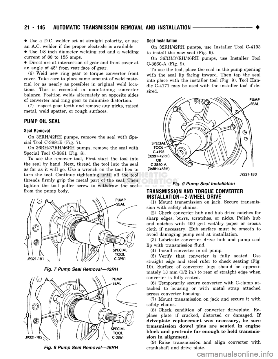
On 32RH/42RH pumps, remove the seal with Spe
cial Tool C-3981B (Fig. 7).
On 36RH/37RH/46RH pumps, remove the seal with
Special Tool C-3861 (Fig. 8). To use the remover tool, First start the tool into
the seal by hand. Next, thread the tool into the seal as far as it will go. Use a wrench on the tool hex to
turn the tool. Continue tightening until all the tool
threads firmly grip the metal part of the seal. Then
tighten the tool puller screw to withdraw the seal
from the pump body.
Fig. 7 Pump Seal Removal—42RH Fig. 8 Pump Seal Removal—46RH
Seal
Installation
On 32RH/42RH pumps, use Installer Tool C-4193
to install the new seal (Fig. 9).
On 36RH/37RH/46RH pumps, use Installer Tool
C-3860-A (Fig. 9).
To use the tool, place the seal in the pump opening
with the seal lip facing inward. Then tap the seal into place with the installer tool (Fig. 9). Tool Han
dle C-4171 may be used with the installer tool if de sired.
J932M80
Fig. 9 Pump Seal Installation
TRANSMISSION
AND TORQUE CONVERTER INSTALLATION—2-WHEEL DRIVE
(1) Mount transmission on jack. Secure transmis
sion with safety chains. (2) Check converter hub and hub drive notches for
sharp edges, burrs, scratches, or nicks. Polish hub
and notches with 400 grit wet/dry paper or crocus
cloth if necessary. Hub surface must be smooth to avoid damaging pump seal at installation. (3) Lubricate converter drive hub and pump seal
lip with transmission fluid. (4) Install converter in oil pump.
(5) Verify that converter is fully seated. Use
straight edge and steel ruler to check seating (Fig.
10).
Surface of converter lugs should be approxi
mately 13 mm (1/2 in.) to rear of straight edge when
converter is fully seated. (6) Temporarily secure converter with C-clamp at
tached to housing or with metal strap attached across converter housing. (7) Mount transmission on jack and secure it with
safety chains. (8) Check condition of converter driveplate. Re
place plate if cracked, distorted or damaged. If driveplate replacement was necessary, be sure
transmission dowel pins are seated in engine
block and protrude far enough to held transmis sion in alignment. (9) Raise transmission and align converter with
crankshaft and drive plate.
Page 1149 of 1502
21 - 148
AUTOMATIC TRANSMISSION REMOVAL
AND
INSTALLATION
•
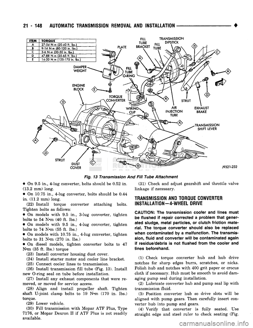
ITEM
TORQUE
A
27-54
N-m
(20-40
ft. lbs.)
B
9-14
N-m
(80-120
in.
lbs.)
C
3-6 N-m
(30-50
in. lbs.)
D
47-88
N-m
(35-65
ft. lbs.)
E
14-20 N-m
(125-175
in. lbs.)
PLATE
FILL
TUBE
BRACKET
TRANSMISSION
DIPSTICK
DAMPER
WEIGHT
STRUT
DUST
COVER
J9321-232
Fig. 13 Transmission And Fill Tube Attachment
3-lug converter, tighten
4-lug converter, tighten • On 9.5 in., 4-lug converter, bolts should be 0.52 in.
(13.2 mm) long.
• On 10.75 in., 4-lug converter, bolts should be 0.44
in. (11.2 mm) long. (22) Install torque converter attaching bolts.
Tighten bolts as follows:
• On models with 9.5 in.,
bolts to 54 Nnn (40 ft. lbs.) • On models with 9.5 in.,
bolts to 74 Nnn (55 ft. lbs.) • On models with 10.75 in., 4-lug converter, tighten
bolts to 31 Nnn (270 in. lbs.)
• On diesel models, tighten converter bolts to 47
Nnn (35 ft. lbs.) torque (23) Install converter housing dust cover. (24) Install starter motor and cooler line bracket.
(25) Connect cooler lines to transmission.
(26) Install transmission fill tube (Fig. 13). Install
new O-ring seal on tube before installation. (27) Install any exhaust components that were re
moved, or moved for service access. (28) Align and install propeller shaft. Tighten
shaft U-joint clamp bolts to 19 Nnn (170 in. lbs.)
torque. (29) Lower vehicle.
(30) Fill transmission with Mopar ATF Plus, Type
7176,
or Mopar Dexron II if ATF Plus is not readily
available. (31) Check and adjust gearshift and throttle valve
linkage if necessary.
TRANSMISSION
AND
TORQUE CONVERTER INSTALLATION—4-WHEEL DRIVE
CAUTION:
The
transmission cooler
and
lines must be flushed
if
repair
corrected
a
problem that gener
ated
sludge,
metal particles,
or
clutch friction mate rial.
The
torque
converter
should
also
be replaced
when contaminated
by a
malfunction.
The
transmis
sion,
fluid
and
converter
will
be
contaminated again if residue/debris
is not
flushed from
the
cooler
and
lines
beforehand.
(1) Check torque converter hub and hub drive
notches for sharp edges burrs, scratches, or nicks.
Polish hub and notches with 400 grit paper or crocus
cloth if necessary. Hub must be smooth to avoid dam aging pump seal during installation.
(2) Lubricate converter hub and pump seal lip with
transmission fluid.
(3) Position converter hub so drive slots will be
aligned with pump gears. Then carefully insert con
verter hub into pump and gears.
(4) Verify that converter is fully seated. Use
straight edge and steel ruler to check seating (Fig.
Page 1150 of 1502
•
AUTOMATIC
TRANSMISSION
REMOVAL
AND
INSTALLATION
21 - 149
10).
Surface of converter lugs should be approxi
mately 13 mm (1/2 in.) to rear of straight edge when converter is fully seated.
(5) Temporarily secure converter in pump and
housing with C-clamp attached to housing edge, or
with metal strap attached across converter housing.
(6) Position transmission on jack. Secure transmis
sion to jack with safety chains.
(7) Check condition of converter driveplate. Re
place plate if cracked, distorted or damaged. If driveplate replacement was necessary, be sure
transmission dowel pins are seated in engine block and protrude far enough to held transmis sion in alignment.
(8) Coat pilot hub of torque converter with trans
mission fluid.
(9) Raise transmission and align converter with
drive plate and crankshaft.
(10) Move transmission forward. Then raise, lower
or tilt transmission to align converter housing with
dowels on engine block.
(11) Rotate converter to align marks scribed on
converter and driveplate. Offset holes in plate are
next to 1/8 in. hole in inner circle of plate (Fig. 1).
(12) Carefully work transmission forward and over
engine block dowels until converter hub is seated in crankshaft.
(13) Install bolts attaching converter housing to
engine.
(14) Install crossmember.
(15) Lower transmission onto crossmember and in
stall bolts attaching transmission and insulator to
crossmember (Figs. 4 and 5). (16) Remove fixture used to support engine.
(17) Connect vehicle speed sensor wires. (18) Install new plastic retainer grommet on any
shift linkage rod or lever that was disconnected. Old
grommets should not be reused. Use pry tool to re
move rod from grommet and cut away old grommet.
Use pliers to snap new grommet into lever and to snap rod into grommet. (19) Connect gearshift and throttle linkage to
transmission. (20) Connect wires to park/neutral position switch,
transmission solenoids and to oxygen sensor. Be sure
transmission harnesses are properly routed.
CAUTION:
It is essential
that
correct length
bolts
be
used
to
attach
the
converter
to the
driveplate.
Bolts
that
are too long
will
damage
the
clutch
surface
in
the converter. If new
bolts
are required, use the
bolts
specified in this procedure and in the parts
book
only.
(21) Verify converter bolt length. Bolt measure
ment is from bottom (underside) of bolt head to end
of bolt threads. • On 9.5 in., 3-lug converter, bolts should be 11.7
mm (0.46 in.) long.
• On 9.5 in., 4-lug converter, bolts should be 13.2
mm (0.52 in.) long.
• On 10.0 in., 4-lug converter, bolts should be 13.2
mm (0.52 in.) long.
• On 10.75 in., 4-lug converter, bolts should be 11.2
mm (0.44 in.) long.
(22) Install torque converter bolts. Tighten bolts as
follows:
• On models with 9.5 in., 3-lug converter, tighten
bolts to 54 Nnn (40 ft. lbs.).
• On models with 9.5 in., 4-lug converter, tighten
bolts to 74 Nnn (55 ft. lbs.).
• On models with 10.0 in., 4-lug converter, tighten
bolts to 74 Nnn (55 ft. lbs.) torque.
• On models with 10.75 in., 4-lug converter, tighten
bolts to 31 Nnn (270 in. lbs.).
• On diesel models with 12.2 in. converter, tighten
bolts to 47 Nnn (35 ft. lbs.) torque.
(23) Install converter housing access cover. (24) Install starter motor and cooler line bracket.
(25) Connect cooler lines to transmission.
(26) Install transmission fill tube. Install new
O-ring seal on tube before installation.
(27) Install any exhaust components removed for
service access. (28) Support transfer case on transmission jack.
Secure transfer case to jack with safety chains. (29) Install gasket on transmission adapter. Coat
gasket with Mopar perfect, seal, or silicone sealer be
forehand. (30) Install transfer case on transmission. Tighten
transfer case attaching nuts to 47 Nnn (35 ft. lbs.) torque. (31) Remove jack supporting transfer case.
(32) Connect transfer case shift lever to range le
ver. (33) Align and install propeller shafts. Tighten
clamp bolts to 19 Nnn 170 in. lbs.) torque. (34) Install transfer case skid plate and crossmem
ber. (35) Lower vehicle.
(36) Fill transmission with Mopar ATF Plus, Type
7176, or Mopar Dexron II if ATF Plus is not readily
available. (37) Check and adjust gearshift, throttle valve and
transfer case shift linkages if necessary.
OVERDRIVE
UNIT
REMOVAL—42RH/46RH
The following removal and installation procedures
apply to the 42RH/46RH overdrive unit only. If the
complete transmission assembly must be removed,
refer to the Transmission And Converter Removal and Installation procedures. (1) Shift transmission into Park.
(2) Raise vehicle.
Page 1151 of 1502
21 - 150
AUTOMATIC TRANSMISSION REMOVAL
AND
INSTALLATION
• (3) Remove transmission oil pan, remove gasket,
drain oil and reinstall pan. (4) If overdrive unit had malfunctioned, or if fluid
is contaminated, remove entire transmission. If diag
nosis indicated overdrive clutch or governor problems
only, remove overdrive unit only.
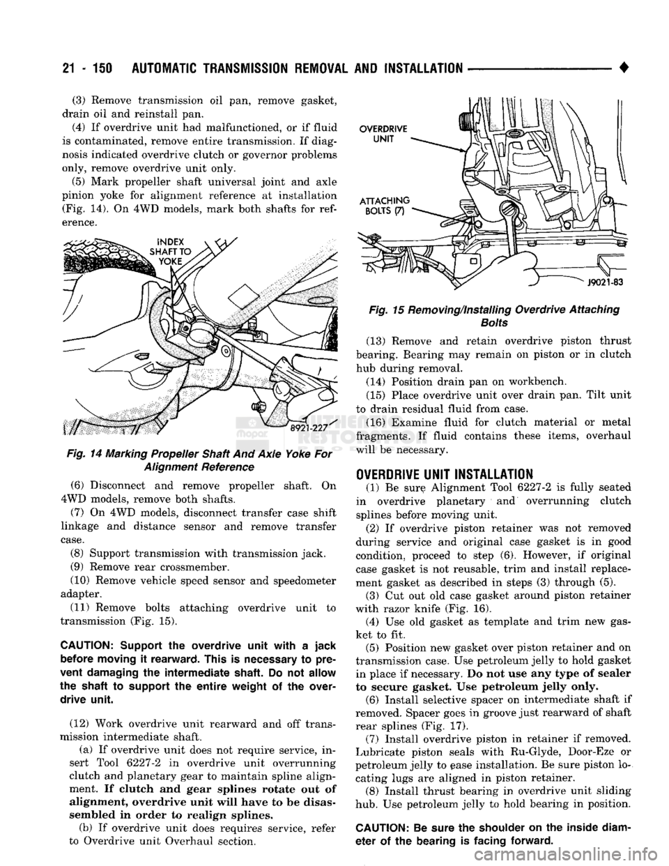
(5) Mark propeller shaft universal joint and axle
pinion yoke for alignment reference at installation (Fig. 14). On 4WD models, mark both shafts for
ref
erence.
Fig.
14 Marking Propeller Shaft And Axle Yoke For
Alignment
Reference
(6) Disconnect and remove propeller shaft. On
4WD models, remove both shafts.
(7) On 4WD models, disconnect transfer case shift
linkage and distance sensor and remove transfer
case.
(8) Support transmission with transmission jack.
(9) Remove rear crossmember.
(10) Remove vehicle speed sensor and speedometer
adapter.
(11) Remove bolts attaching overdrive unit to
transmission (Fig. 15).
CAUTION:
Support
the
overdrive unit with
a
jack before moving
it
rearward. This
is
necessary
to
pre
vent damaging
the
intermediate shaft.
Do not
allow
the shaft
to
support
the
entire
weight
of the
over drive unit.
(12) Work overdrive unit rearward and off trans
mission intermediate shaft.
(a) If overdrive unit does not require service, in
sert Tool 6227-2 in overdrive unit overrunning
clutch and planetary gear to maintain spline align
ment. If clutch and gear splines rotate out of
alignment, overdrive unit will have to be disas
sembled in order to realign splines.
(b) If overdrive unit does requires service, refer
to Overdrive unit Overhaul section.
Fig.
15 Removing/Installing Overdrive Attaching
Bolts
(13) Remove and retain overdrive piston thrust
bearing. Bearing may remain on piston or in clutch hub during removal.
(14) Position drain pan on workbench.
(15) Place overdrive unit over drain pan. Tilt unit
to drain residual fluid from case. (16) Examine fluid for clutch material or metal
fragments. If fluid contains these items, overhaul
will be necessary.
OVERDRIVE
UNIT INSTALLATION
(1) Be sure Alignment Tool 6227-2 is fully seated
in overdrive planetary and overrunning clutch
splines before moving unit.
(2) If overdrive piston retainer was not removed
during service and original case gasket is in good
condition, proceed to step (6). However, if original case gasket is not reusable, trim and install replace
ment gasket as described in steps (3) through (5).
(3) Cut out old case gasket around piston retainer
with razor knife (Fig. 16). (4) Use old gasket as template and trim new gas
ket to fit. (5) Position new gasket over piston retainer and on
transmission case. Use petroleum jelly to hold gasket in place if necessary. Do not use any type of sealer
to secure gasket. Use petroleum jelly only. (6) Install selective spacer on intermediate shaft if
removed. Spacer goes in groove just rearward of shaft
rear splines (Fig. 17). (7) Install overdrive piston in retainer if removed.
Lubricate piston seals with Ru-Glyde, Door-Eze or
petroleum jelly to ease installation. Be sure piston lo
cating lugs are aligned in piston retainer. (8) Install thrust bearing in overdrive unit sliding
hub.
Use petroleum jelly to hold bearing in position.
CAUTION:
Be
sure
the
shoulder
on the
inside diam
eter
of the
bearing
is
facing forward.
Page 1351 of 1502
21 - 350 NP241
TRANSFER CASE
• NP241 TRANSFER CASE
INDEl
page
Checking
Fluid
Level
351
Component Cleaning
and
Inspection
359
Fluid
Drain/Refill
351
General
Information
350
Recommended
Lubricant
.................. 350
Service
Diagnosis
....................... 350
Shift
Linkage
Adjustment
354
Speedometer Adapter/Distance
Sensor
Service
. 352
page
Speedometer Gear, Shaft
Seal,
Bearing
and
Retainer
Service
352
Transfer
Case
Assembly
.................. 361
Transfer
Case
Bearing Replacement
......... 360
Transfer
Case
Disassembly
................ 356
Transfer
Case
Identification ................ 350
Transfer
Case
Installation
................. 356
Transfer
Case
Removal
356
GENERAL
INFORMATION
The NP241 is a part-time transfer case with a low-
range gear system. It has three operating ranges
plus a Neutral position. The low range system pro vides a gear reduction ratio for increased low speed
torque capability. NP241 operating ranges are: 2-high, 4-high and 4-low. The NP241 has an aluminum, two-piece gear case.
Drive sprockets and an interconnecting drive chain are used to transmit engine torque to the propeller
shafts.
Four-wheel high and low ranges are undifferenti
ated. The transfer case is not designed for continuous
operation in 4WD range on hard or paved surfaces.
Four wheel drive ranges are recommended for off
road operation, or on snow covered or similar low
traction surfaces. A front axle disconnect system is used to achieve
two-wheel drive mode. The axle disconnect vacuum motor is actuated by a vacuum switch on the transfer
case.
The switch is operated by the transfer case
range rod. Two-wheel drive range is used for on road, high
way operation. The four-wheel drive ranges are for off road operation or when the vehicle is driven on
paved road surfaces covered by snow, ice or similar low traction elements.
TRANSFER CASE
IDENTIFICATION
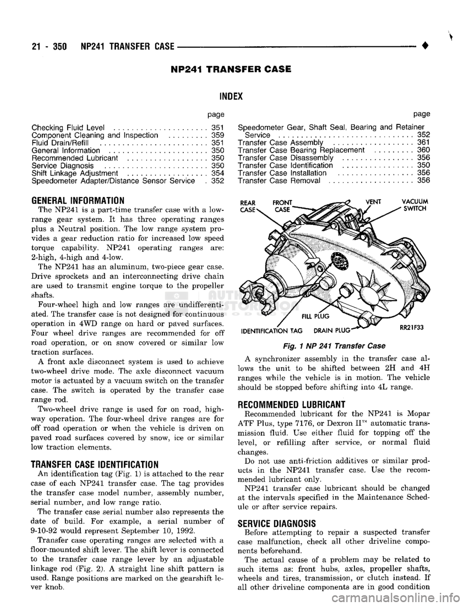
An identification tag (Fig, 1) is attached to the rear
case of each NP241 transfer case. The tag provides
the transfer case model number, assembly number, serial number, and low range ratio. The transfer case serial number also represents the
date of build. For example, a serial number of 9-10-92 would represent September 10, 1992. Transfer case operating ranges are selected with a
floor-mounted shift lever. The shift lever is connected
to the transfer case range lever by an adjustable linkage rod (Fig. 2). A straight line shift pattern is
used. Range positions are marked on the gearshift le
ver knob.
Fig.
1 NP 241 Transfer
Case
A synchronizer assembly in the transfer case al
lows the unit to be shifted between 2H and 4H
ranges while the vehicle is in motion. The vehicle should be stopped before shifting into 4L range.
RECOMMENDED
LUBRICANT
Recommended lubricant for the NP241 is Mopar
ATF Plus, type 7176, or Dexron II™ automatic trans
mission fluid. Use either fluid for topping off the
level, or refilling after service, or normal fluid
changes. Do not use anti-friction additives or similar prod
ucts in the NP241 transfer case. Use the recom
mended lubricant only. NP241 transfer case lubricant should be changed
at the intervals specified in the Maintenance Sched
ule or after service repairs.
SERVICE
DIAGNOSIS
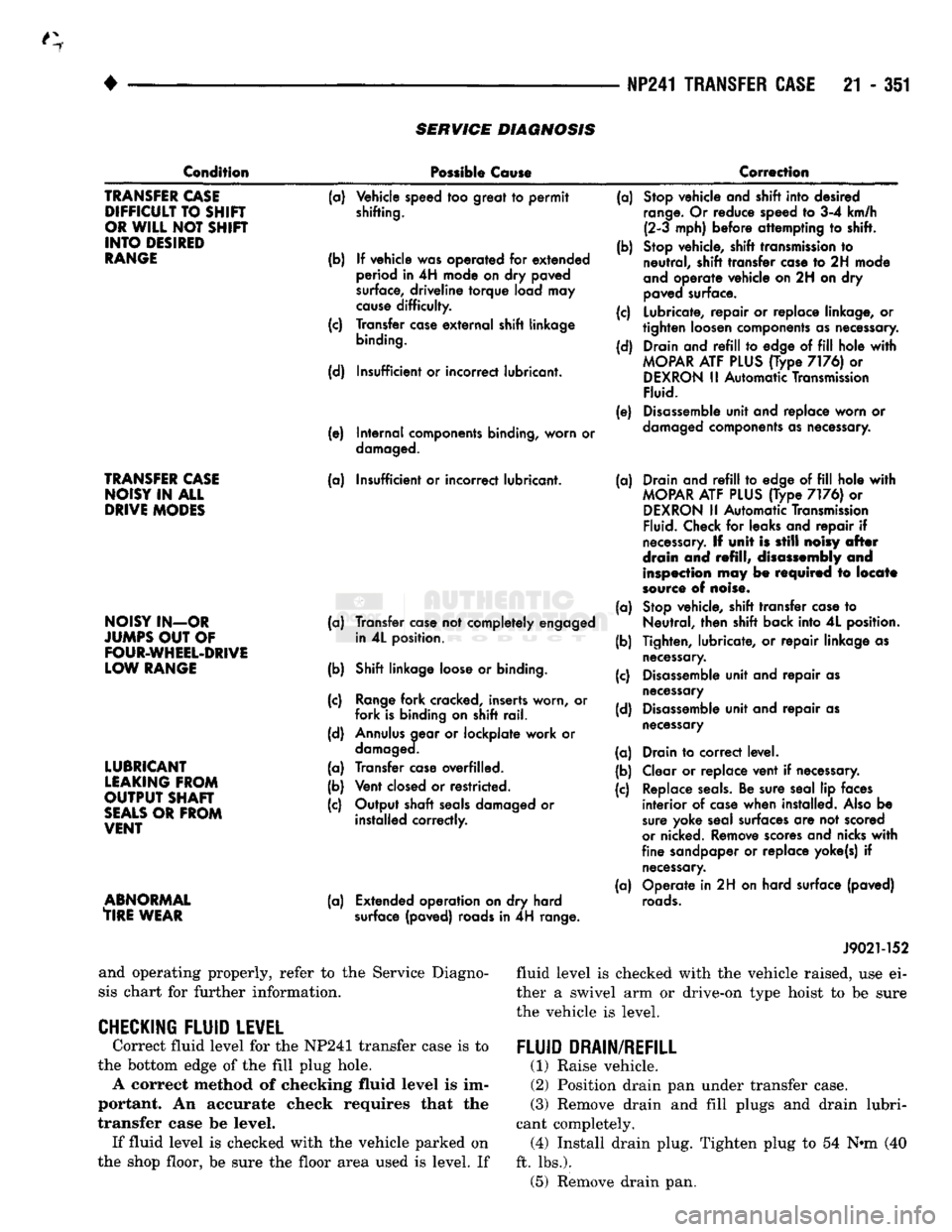
Before attempting to repair a suspected transfer
case malfunction, check all other driveline compo
nents beforehand. The actual cause of a problem may be related to
such items as: front hubs, axles, propeller shafts,
wheels and tires, transmission, or clutch instead. If all other driveline components are in good condition
Page 1352 of 1502
•
NP241 TRANSFER CASE
21 - 351
SERVICE
DIAGNOSIS
Condition
Possible
Cause
Correction
TRANSFER
CASE
DIFFICULT
TO
SHIR
OR
WILL
NOT
SHIFT
INTO
DESIRED
RANGE
TRANSFER
CASE
NOISY
IN ALL
DRIVE
MODES
NOISY
IN-OR
JUMPS
OUT
OF
FOUR-WHEEL-DRIVE
LOW
RANGE
LUBRICANT
LEAKING
FROM
OUTPUT
SHAFT
SEALS
OR
FROM
VENT
ABNORMAL
TIRE
WEAR
(a)
Vehicle speed
too
great
to permit
shifting.
(b)
If
vehicle was operated
for
extended
period
in 4H
mode
on dry
paved
surface,
driveline
torque
load
may
cause
difficulty.
(c) Transfer
case
external
shift linkage
binding.
(d) Insufficient
or
incorrect lubricant.
(e) Internal components binding, worn
or
damaged.
(a) Insufficient
or
incorrect lubricant.
(a) Transfer
case
not
completely engaged in
4L
position.
(b) Shift linkage
loose
or
binding.
(c)
Range
fork cracked, inserts worn,
or
fork is binding
on
shift rail.
(d)
Annulus
gear
or
lockplate work
or
damaged.
(a) Transfer
case
overfilled.
(b) Vent
closed
or
restricted.
(c) Output shaft
seals
damaged
or
installed correctly.
(a) Extended operation
on dry
hard
surface
(paved) roads
in 4H
range. (a)
Stop
vehicle and shift into desired
range.
Or
reduce speed
to 3-4
km/h (2-3 mph) before attempting
to
shift.
(b)
Stop
vehicle, shift
transmission
to
neutral, shift transfer
case
to 2H
mode
and
operate vehicle on
2H on dry
paved
surface.
(c) Lubricate, repair
or
replace linkage,
or
tighten loosen components as necessary.
(d) Drain and
refill to
edge
of fill
hole
with
MOPAR
ATF
PLUS
(Type
7176) or
DEXRON
II
Automatic
Transmission
Fluid.
(e)
Disassemble
unit and replace worn
or
damaged
components
as necessary.
(a) Drain and
refill to
edge
of fill
hole
with
MOPAR
ATF
PLUS
(Type
7176) or
DEXRON
II
Automatic
Transmission
Fluid.
Check
for
leaks and repair
if
necessary.
If
unit
is
still
noisy
after
drain
and
refill,
disassembly
and
inspection
may be
required
to
locate
source
of
noise.
(a)
Stop
vehicle, shift transfer
case
to
Neutral, then shift back into
4L
position.
(b) Tighten, lubricate,
or
repair linkage
as
necessary.
(c)
Disassemble
unit and repair
as
necessary
(d)
Disassemble
unit and repair
as
necessary
(a) Drain
to
correct level.
(b) Clear
or
replace vent
if
necessary.
(c) Replace
seals.
Be sure seal
lip
faces interior
of
case
when installed.
Also
be
sure
yoke seal surfaces
are not
scored
or
nicked. Remove
scores
and nicks
with
fine sandpaper
or
replace yoke(s)
if
necessary.
(a) Operate
in 2H on
hard surface (paved)
roads.
and operating properly, refer to the Service Diagno
sis chart for further information.
CHECKING FLUID LEVEL
Correct fluid level for the NP241 transfer case is to
the bottom edge of the fill plug hole. A correct method of checking fluid level is im
portant. An accurate check requires that the
transfer case be level. If fluid level is checked with the vehicle parked on
the shop floor, be sure the floor area used is level. If J9021-152
fluid level is checked with the vehicle raised, use ei
ther a swivel arm or drive-on type hoist to be sure
the vehicle is level.
FLUID DRAIN/REFILL
(1) Raise vehicle.
(2) Position drain pan under transfer case.
(3)
Remove drain and fill plugs and drain lubri
cant completely. (4) Install drain plug. Tighten plug to 54 N»m (40
ft. lbs.). (5) Remove drain pan.
Page 1353 of 1502
21 - 352 NP241
TRANSFER
CASE
—
•
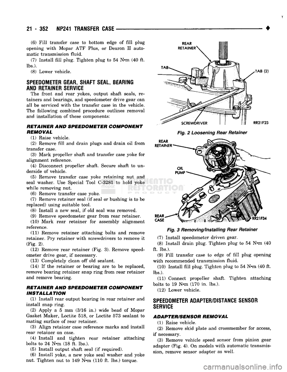
Fig.
2
Loosening
Rear Retainer
Fig.
3 Removing/Installing Rear Retainer
(7) Install speedometer driven gear.
(8) Install drain plug. Tighten plug to 54 N-m (40
ft. lbs.). (9) Fill transfer case to edge of fill plug opening
with recommended transmission fluid. (10) Install fill plug. Tighten plug to 54 N-m (40 ft.
lbs.).
(11) Connect propeller shaft. Tighten attaching
bolts to 19 N-m (170 in. lbs.).
(12) Lower vehicle.
SPEEDOMETER
ADAPTER/DISTANCE
SENSOR
SERVICE
ADAPTER/SENSOR
REMOVAL
(1) Raise vehicle.
(2) Remove skid plate and crossmember for access,
if necessary. (3) Remove vehicle speed sensor from pinion gear
adapter (Fig. 4). On models with automatic transmis
sion, remove sensor adapter as well.
(6) Fill transfer case to bottom edge of fill plug
opening with Mopar ATF Plus, or Dexron II auto
matic transmission fluid.
(7) Install fill plug. Tighten plug to 54 N«m (40 ft.
lbs.).
(8) Lower vehicle.
SPEEDOMETER
GEAR, SHAFT
SEAL,
BEARING
AND RETAINER SERVICE
The front and rear yokes, output shaft seals, re
tainers and bearings, and speedometer drive gear can all be serviced with the transfer case in the vehicle.
The following combined procedure outlines removal and installation of these components:
RETAINER
AND
SPEEDOMETER COMPONENT REMOVAL
(1) Raise vehicle.
(2) Remove fill and drain plugs and drain oil from
transfer case. (3) Mark propeller shaft and transfer case yoke for
alignment reference. (4) Disconnect propeller shaft. Secure shaft to un
derside of vehicle. (5) Remove transfer case yoke retaining nut and
seal washer. Use Special Tool C-3281 to hold yoke
while removing nut. (6) Remove transfer case yoke. (7) Remove retainer seal (if seal or bushing is to be
replaced) using suitable tool.
(8) Install a new seal, if old seal was removed.
(9) Remove speedometer gear from rear retainer.
(10) Mark rear retainer for assembly alignment
reference. (11) Remove retainer attaching bolts and remove
retainer. Pry retainer with screwdrivers to remove it (Fig. 2). (12) Remove rear retainer (Fig. 3). Remove speed
ometer drive gear, if necessary.
(13) Completely clean off old sealant.
(14) If the retainer or bearing are to be replaced,
remove bearing retainer snap ring from rear retainer
and remove bearing.
RETAINER
AND
SPEEDOMETER COMPONENT INSTALLATION
(1) Install rear output bearing in rear retainer and
install snap ring. (2) Apply a 5 mm (3/16 in.) wide bead of Mopar
Gasket Maker, Loctite 518, or Loctite 573 sealant to
mating surface of rear retainer.
(3) Align retainer case reference marks and install
rear retainer on case. (4) Install and tighten rear retainer attaching
bolts to 24 N«m (18 ft. lbs.). (5) Install output shaft seal (if required).
(6) Install yoke, a new yoke seal washer and yoke
nut. Tighten nut to 149 N-m (110 ft. lbs.) torque.
Page 1365 of 1502
21 - 364
TRANSMISSION/TRANSFER
CASE
SPECIFICATIONS
•
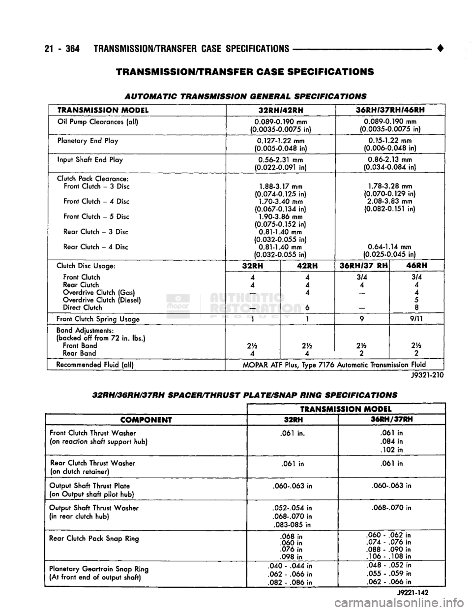
AUTOMATIC TRANSMISSION
GENERAL SPECIFICATIONS
TRANSMISSION
MODEL
32RHI42RH
'36RH/37RHI46RH
Oil Pump Clearances (all)
0.089-0.190
mm
(0.0035-0.0075
in)
0.089-0.190
mm
(0.0035-0.0075
in)
Planetary End Play
0.127-1.22
mm
(0.005-0.048
in)
0.15-1.22
mm
(0.006-0.048
in)
Input Shaft End Play
0.56-2.31
mm
(0.022-0.091
in)
0.86-2.13
mm
(0.034-0.084
in)
Clutch Pack Clearance: Front Clutch - 3
Disc
Front Clutch - 4
Disc
Front Clutch - 5
Disc
Rear Clutch - 3
Disc
Rear Clutch - 4
Disc
1.88-3.17
mm
(0.074-0.125
in)
1.70-3.40
mm
(0.067-0.134
in)
1.90-3.86
mm
(0.075-0.152
in)
0.81-1.40
mm
(0.032-0.055
in)
0.81-1.40
mm
(0.032-0.055
in)
1.78-3.28
mm
(0.070-0.129
in)
2.08-3.83
mm
(0.082-0.151
in)
0.64-1.14
mm
(0.025-0.045
in)
Clutch
Disc
Usage:
Front Clutch
Rear Clutch
Overdrive Clutch (Gas)
Overdrive Clutch (Diesel) Direct Clutch 32RH
42RH 36RH/37 RH 46RH
Clutch
Disc
Usage:
Front Clutch
Rear Clutch
Overdrive Clutch (Gas)
Overdrive Clutch (Diesel) Direct Clutch 4
4
4
4 4
6 3/4
4 3/4
4
4
5
8
Front Clutch Spring
Usage
1 1
9
9/11
Band
Adjustments:
(backed off from 72 in. lbs.) Front
Band
Rear
Band
2Vi
4 2Yi
4 214
2
Th
2
Recommended Fluid (all)
MOPAR
ATF
Plus,
Type 7176 Automatic Transmission Fluid
J9321-210
32RH/36RH/37RH
SPACER/THRUST
PLATE/SNAP
RING
SPECIFICATIONS
TRANSMISSION
MODEL
COMPONENT
32RH 36RH/37RH
Front Clutch Thrust Washer
(on reaction shaft
support
hub) .061 in.
.061 in
.084 in
.102 in
Rear Clutch Thrust Washer
(on clutch
retainer)
.061 in
.061 in
Output Shaft Thrust Plate (on Output shaft pilot hub)
.060-.063
in
.060-.063
in
Output Shaft Thrust Washer (in
rear
clutch hub)
.052-.054
in
.068-.070
in
.083-085
in
.068-.070
in
Rear Clutch Pack
Snap
Ring
.068 in
.060 in
.076 in
.098 in .060 - .062 in
.074 - .076 in
.088 - .090 in .106 - .108 in
Planetary Geartrain
Snap
Ring
(At
front
end of output shaft) .040 - .044 in
.062 - .066 in .082 - .086 in .048 - .052 in
.055 - .059 in .062 - .066 in
J922M42
TRANSMISSION/TRANSFER
CASE
SPECIFICATIONS