1993 DODGE TRUCK automatic transmission fluid
[x] Cancel search: automatic transmission fluidPage 1095 of 1502
21
- 14
AUTOMATIC TRANSMISSION—32RH/36RH/37RH/42RH/46RH
•
MATERIAL:
3/16
INCH
STEEL
STOCK
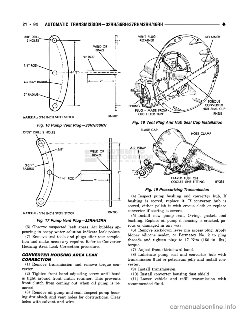
Fig. 16 Pump Vent Piug-36RH/46RH
13/32" DRILL
2
HOLES MATERIAL:
3/16
INCH
STEEL
STOCK
KN/aj
Fig. 17 Pump Vent Plug-32RH/42RH
(6) Observe suspected leak areas. Air bubbles ap
pearing in soapy water solution indicate leak points.
(7) Remove test tools and plugs after test comple
tion and make necessary repairs. Refer to Converter Housing Area Leak Correction procedure.
CONVERTER HOUSING AREA LEAK
CORRECTION
(1) Remove transmission and remove torque con
verter.
(2) Tighten front band adjusting screw until band
is tight around front clutch retainer. This prevents
front clutch from coming out when oil pump is re
moved.
(3) Remove oil pump and seal. Inspect pump hous
ing drainback and vent holes for obstructions. Clear
holes with solvent and wire.
COOLER
LINE
FITTING
RY254
Fig. 19 Pressurizing Transmission (4) Inspect pump bushing and converter hub. If
bushing is scored, replace it. If converter hub is scored, either polish it with crocus cloth or replace
converter if scoring is severe.
(5) Install new pump seal, O-ring, gasket, and
bushing. Replace oil pump if housing is cracked, po
rous or damaged in any way.
(6)
Remove kickdown lever pin access plug. Apply
Mopar silicone sealer, or Permatex No. 2 to plug
threads and tighten plug to 17 N*m (150 in. lbs.) torque.
(7) Adjust front (kickdown) band.
(8) Lubricate pump seal and converter hub with
transmission fluid or petroleum jelly and install con
verter.
(9) Install transmission.
(10) Install converter housing dust shield
(11) Lower vehicle and refill transmission with
recommended fluid.
Page 1096 of 1502
•
AUTOMATIC
TRANSMISSION—32RH/36RH/37RH/42RH/46RH
21 - ii
DIAGNOSIS
CHARTS AND HYDRAULIC
FLOW
DIAGRAMS
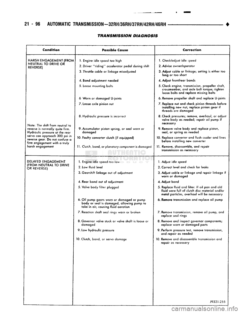
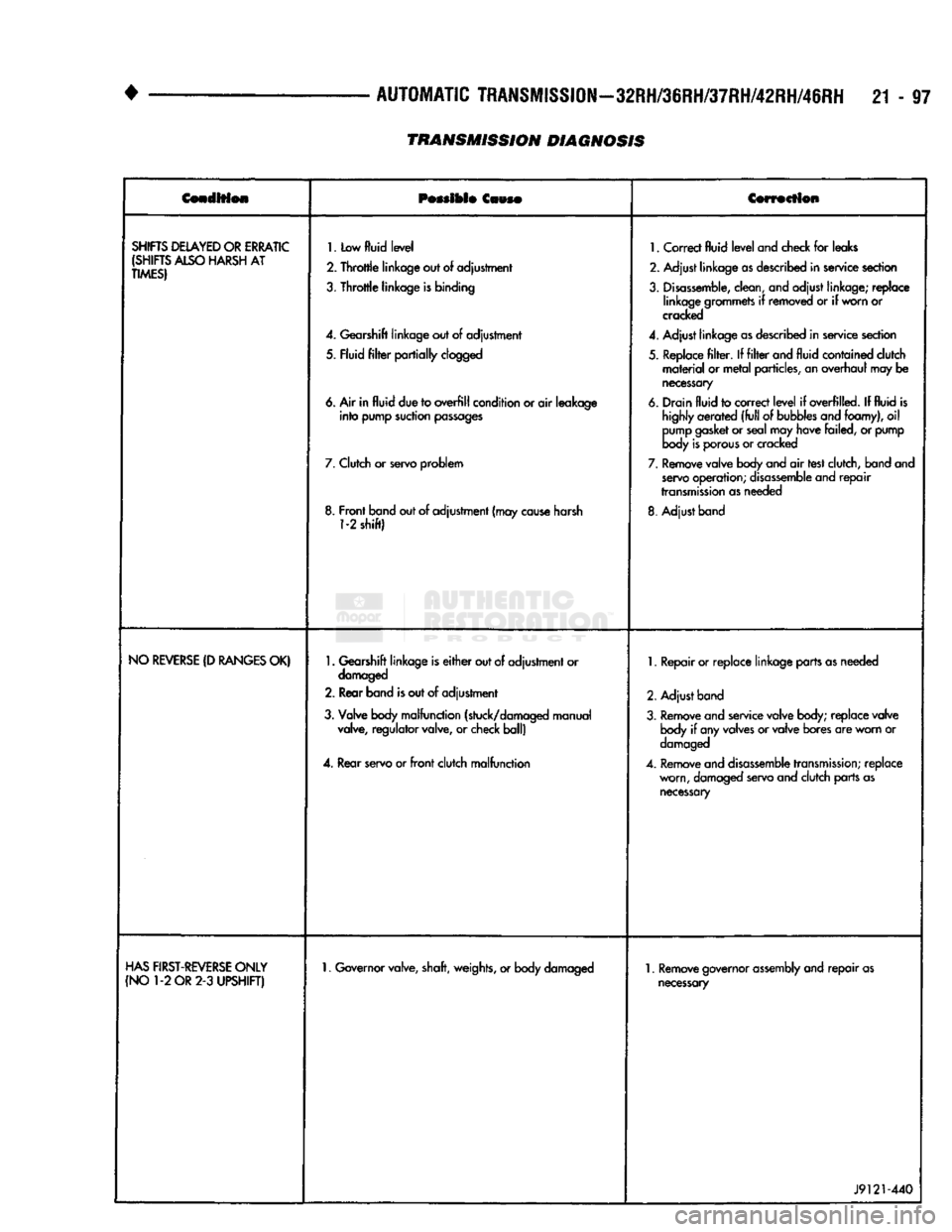
The diagnosis charts and hydraulic flow diagrams
provide additional reference for transmission diagno
sis.
The diagnosis charts provide general information
on a variety of transmission, overdrive unit and con
verter clutch fault conditions. The Transmission Unit diagnosis charts apply to all transmission models.
The Overdrive Unit charts apply to the four speed
transmissions only.
The hydraulic flow diagrams outline transmission
fluid flow and hydraulic circuitry. The flow diagrams also provide basic working pressures for the various
gear ranges.
Page 1097 of 1502
21 - 96
AUTOMATIC
TRANSMISSION—32RH/36RH/37RH/42RH/46RH
• Condition
Possible
Cause
Correction
HARSH
ENGAGEMENT
(FROM
NEUTRAL
TO
DRIVE
OR
REVERSE)
Note: The shift from
neutral
to
reverse is normally
quite
firm. Hydraulic pressure at the
rear
servo can approach 300 psi in
reverse gear. Do not confuse a
firm
engagement
with
a
truly
harsh engagement
1.
Engine
idle
speed too high
2. Driver "riding" accelerator pedal during shift
3.
Throttle
cable or linkage misadjusted
4. Band adjustment needed
5.
Loose
mounting bolts
6 Worn or damaged
U-joints
7.
Loose
axle
pinion nut
8. Hydraulic pressure is incorrect
9. Accumulator piston spring, or seal worn or damaged
10. Faulty converter clutch (if equipped)
11.
Clutch, band, or
planetary
component
is
damaged 1. Check/adjust
idle
speed
2. Advise owner/operator
3. Adjust cable or linkage; setting is
either
too long or too short
4. Adjust
front/rear
bands
5. Check engine, transmission,
propeller
shaft, crossmember, and
axle
bolt torque;
tighten
loose
bolts and replace
missing
bolts
6. Remove
propeller
shaft and replace
U-joints
7. Replace nut and check pinion threads
before
installing new nut; replace pinion gear if
threads are damaged
8. Check pressures; remove, overhaul, or adjust valve body as needed;
repair
oil pump if
necessary
9. Remove valve body and replace piston,
seal,
or spring as needed
10. Replace converter and flush cooler and lines
before
installing new converter
11.
Remove, disassemble, and
repair
transmission
as necessary
DELAYED
ENGAGEMENT
(FROM
NEUTRAL
TO
DRIVE
OR
REVERSE)
1.
Engine
idle
speed too low
2. Low
fluid
level
3. Gearshift linkage but of adjustment
4. Rear band out of adjustment
5.
Valve body
filter
plugged
6. Oil pump gears worn or damaged or pump body or seal is damaged, allowing pump to
take
in air, causing
fluid
aeration
7. Reaction shaft seal rings worn or broken
8. Governor valve stuck or valve shaft is loose or damaged
9. Low hydraulic pressure
10. Clutch, band, or servo damage
1.
Adjust
idle
speed
2. Correct
level
and check for leaks
3. Adjust cable or linkage and
repair
linkage if worn or damaged
4. Adjust band
5. Replace
fluid
and
filter.
If oil pan and old
fluid
were
full
of clutch
disc
material
and/or
metal
particles, overhaul
will
be necessary
6. Remove transmission and replace oil pump
7. Remove transmission, remove oil pump, and replace seal rings
8. Remove and inspect governor components; replace worn or damaged parts
9. Perform pressure test, remove transmission, and
repair
as needed
10. Remove and disassemble transmission and
repair
as necessary
J9321-255
TRANSMISSION DIAGNOSIS
Page 1098 of 1502
•
AUTOMATIC
TRANSMISSION—32RH/36RH/37RH/42RH/46RH
21 - 97
Cenoltfeie
Possible
Caws®
Cowscilon
SHIFTS
DELAYED
OR
ERRATIC
(SHIFTS
ALSO
HARSH
AT
TIMES)
1.
Low
fluid
level
2.
Throttle
linkage out
of
adjustment
3.
Throttle
linkage
is
binding
4.
Gearshift linkage out
of
adjustment
5. Fluid
filter
partially
clogged
6. Air in
fluid
due to
overfill
condition or
air
leakage
into
pump suction
passages
7.
Clutch
or
servo problem
8. Front band out of adjustment (may
cause
harsh
1-2
shift)
1.
Correct
fluid
level
and check
for
leaks
2. Adjust linkage
as
described in service section
3.
Disassemble,
clean, and adjust linkage; replace linkage grommets
if
removed
or if
worn or
cracked
4.
Adjust linkage
as
described in service section
5. Replace
filter. If filter
and
fluid
contained clutch
material
or
metal
particles, an overhaul may
be
necessary
6. Drain
fluid
to correct
level
if
overfilled.
If
fluid
is
highly
aerated
(full
of
bubbles
and foamy),
oil
pump
gasket
or seal may have failed,
or
pump
body
is
porous
or cracked
7.
Remove valve body and
air
test clutch, band and
servo
operation;
disassemble
and
repair
transmission
as needed
8. Adjust band
NO
REVERSE
(D
RANGES
OK)
1.
Gearshift linkage is
either
out of adjustment or
damaged
2. Rear band
is
out
of
adjustment
3. Valve body malfunction (stuck/damaged manual valve, regulator valve,
or
check ball)
4.
Rear servo or
front
clutch malfunction
1.
Repair or replace linkage parts as needed
2. Adjust band
3. Remove and service valve body; replace valve body
if
any valves or valve bores are worn
or
damaged
4.
Remove and
disassemble
transmission;
replace worn, damaged servo and clutch parts as
necessary
HAS
FIRST-REVERSE
ONLY
(NO
1-2
OR
2-3
UPSHIFT)
1.
Governor valve, shaft, weights, or body damaged
1.
Remove governor
assembly
and
repair
as
necessary
J9121-440
TRANSMISSION DIAGNOSIS
Page 1099 of 1502
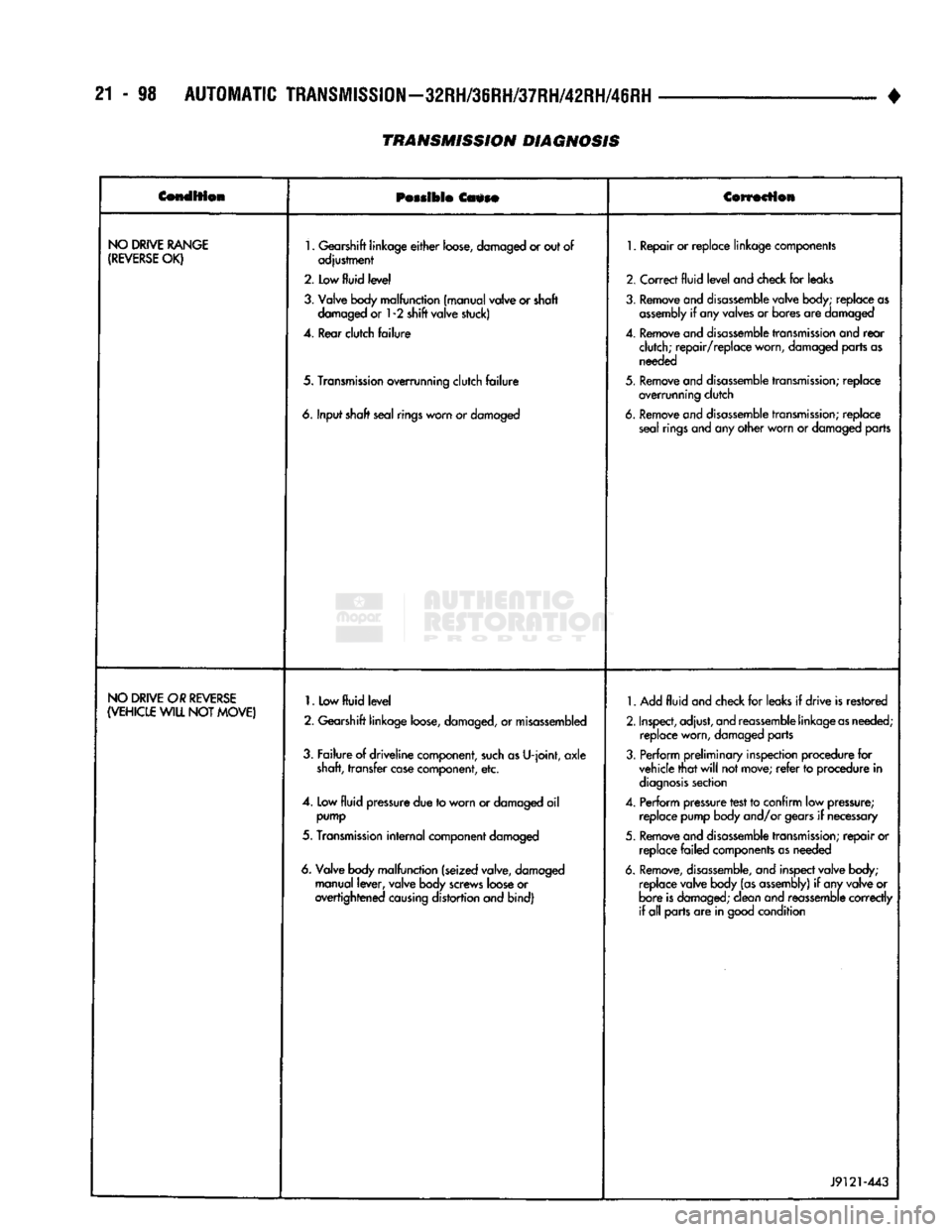
21
- 98
AUTOMATIC
TRANSMISSION-32RH/36RH/37RH/42RH/46RH
•
CendSfion
Possible
Cause Correction
NO
DRIVE
RANGE
(REVERSE
OK)
1.
Gearshift linkage
either
loose,
damaged or out of
adjustment
2. Low
fluid
level
3. Valve body malfunction (manual valve or shaft damaged or
1
-2 shift valve stuck)
4. Rear clutch
failure
5.
Transmission
overrunning clutch
failure
6. Input shaft seal
rings
worn or damaged
1.
Repair or replace linkage components
2. Correct
fluid
level
and check for leaks
3. Remove and
disassemble
valve body; replace as
assembly
if
any valves or bores are damaged
4.
Remove and
disassemble
transmission
and
rear
clutch;
repair/replace
worn, damaged parts as needed
5.
Remove and
disassemble
transmission;
replace overrunning clutch
6. Remove and
disassemble
transmission;
replace seal rings and any
other
worn or damaged parts
NO
DRIVE
OR
REVERSE
(VEHICLE
WILL NOT
MOVE)
1.
Low
fluid
level
2. Gearshift linkage
loose,
damaged, or misassembled
3.
Failure
of
driveline
component,
such
as
U-joint,
axle
shaft, transfer
case
component, etc.
4. Low
fluid
pressure due to worn or damaged
oil
pump
5.
Transmission
internal
component damaged
6. Valve body malfunction (seized valve, damaged manual
lever,
valve body screws
loose
or
overtightened
causing
distortion and bind)
1.
Add
fluid
and check for leaks
if
drive
is restored
2.
Inspect,
adjust, and reassemble linkage
as
needed; replace worn, damaged parts
3. Perform
preliminary
inspection procedure for vehicle
that
will
not
move;
refer
to procedure
in
diagnosis
section
4. Perform pressure test to confirm low pressure; replace pump body and/or
gears
if
necessary
5.
Remove and
disassemble
transmission;
repair
or replace
failed
components
as
needed
6.
Remove,
disassemble,
and inspect valve body; replace valve body (as
assembly)
if
any valve or
bore
is
damaged;
clean and reassemble
correctly
if all parts are in good condition
J9121-443
TRANSMISSION DIAGNOSIS
Page 1100 of 1502
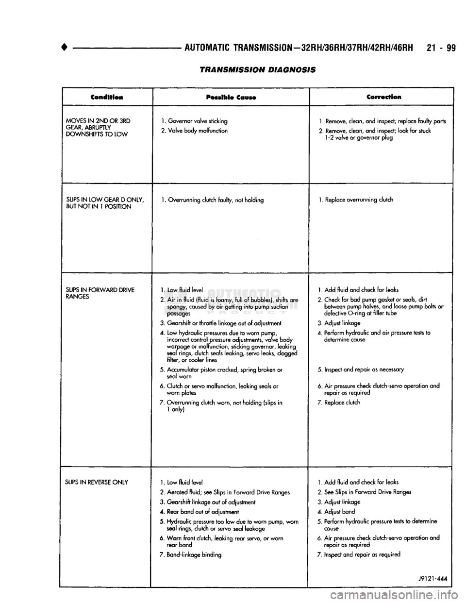
•
AUTOMATIC
TRANSMISSION-32RH/36RH/37RH/42RH/46RH
21 - 99 Condition
Possible
Cause
Correction
MOVES
IN 2ND OR 3RD
GEAR,
ABRUPTLY
DOWNSHIFTS
TO LOW
1.
Governor valve sticking
2. Valve body malfunction
1.
Remove, clean, and inspect; replace
faulty
parts
2. Remove, clean, and inspect; look for stuck
1
-2 valve or governor plug
SLIPS
IN LOW
GEAR
D
ONLY,
BUT
NOT IN 1
POSITION
1.
Overrunning clutch
faulty,
not holding
1.
Replace overrunning clutch
SLIPS
IN
FORWARD
DRIVE
RANGES
1.
Low
fluid
level
2. Air in
fluid
(fluid
is
foamy,
full
of bubbles), shifts are
spongy,
caused by air getting
into
pump suction
passages
3. Gearshift or
throttle
linkage out of adjustment
4. Low hydraulic
pressures
due to worn pump, incorrect control pressure adjustments, valve body
warpage or malfunction, sticking governor, leaking seal
rings,
dutch
seals
leaking, servo leaks, clogged
filter,
or cooler lines
5. Accumulator piston cracked, spring broken or seal worn
6. Clutch or servo malfunction, leaking
seals
or worn plates
7. Overrunning clutch worn, not holding (slips in
1
only)
1.
Add
fluid
and check for leaks
2. Check for bad pump gasket or
seals,
dirt
between
pump halves, and loose pump bolts or
defective
O-ring at
filler
tube
3. Adjust linkage
4. Perform hydraulic and air pressure
tests
to
determine
cause
5. Inspect and
repair
as
necessary
6. Air pressure check clutch-servo operation and
repair
as
required
7. Replace clutch
SLIPS
IN
REVERSE
ONLY
1.
Low
fluid
level
2. Aerated fluid; see
Slips
in Forward Drive
Ranges
3. Gearshift linkage out of adjustment
4. Rear band out of adjustment
5. Hydraulic pressure too low due to worn pump, worn seal
rings,
clutch or servo seal leakage
6. Worn
front
clutch, leaking
rear
servo, or worn
rear
band
7. Band-linkage binding
1.
Add
fluid
and check for leaks
2. See
Slips
in Forward Drive
Ranges
3. Adjust linkage
4. Adjust band
5. Perform hydraulic pressure tests to
determine
cause
6. Air pressure check clutch-servo operation and
repair
as
required
7. Inspect and
repair
as
required
J9121-444
TRANSMISSION DIAGNOSIS
Page 1102 of 1502
+
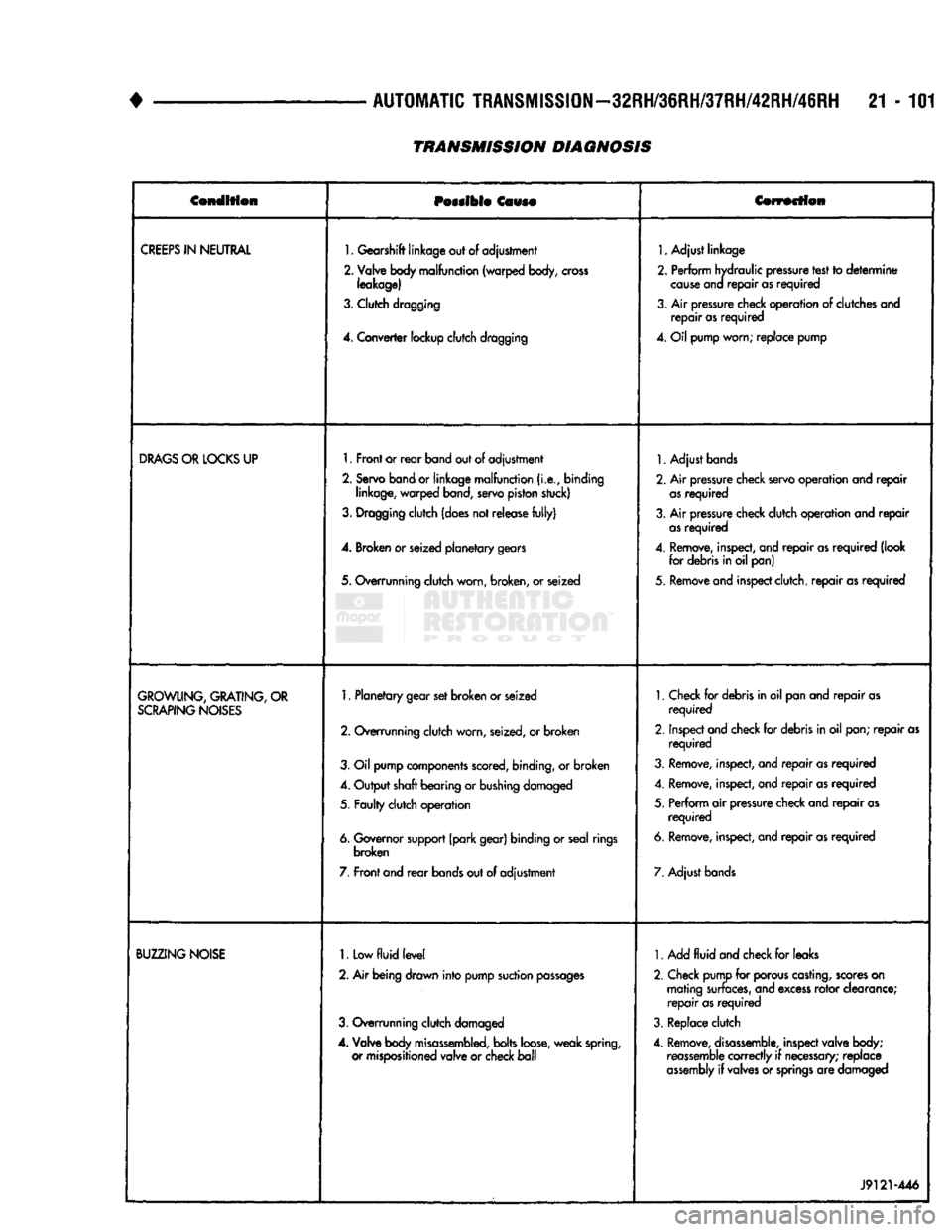
AUTOMATIC TRANSMISSION—32RH/36RH/37RH/42RH/46RH 21 - 101
TRANSMISSION DIAGNOSIS
Condition
Possible
Cause Correction
CREEPS
IN
NEUTRAL
1. Gearshift linkage out of adjustment
2. Valve body malfunction (warped body,
cross
leakage)
3. Clutch dragging
4.
Converter lockup clutch dragging 1. Adjust linkage
2. Perform hydraulic pressure test to
determine
cause
ana
repair
as
required
3. Air pressure check operation of clutches and
repair
as
required
4. Oil pump worn; replace pump
DRAGS
OR
LOCKS
UP 1. Front or
rear
band out of adjustment
2. Servo band or linkage malfunction
(i.e.,
binding linkage, warped band, servo piston stuck)
3. Dragging clutch (does not release
fully)
4. Broken or seized planetary gears
5. Overrunning clutch worn, broken, or seized 1. Adjust bands
2. Air pressure check servo operation and
repair
as
required
3. Air pressure check clutch operation and
repair
as
required
4. Remove, inspect, and
repair
as
required
(look for debris in oil pan)
5. Remove and inspect clutch,
repair
as
required
GROWLING,
GRATING,
OR
SCRAPING
NOISES
1. Planetary gear set broken or seized
2. Overrunning clutch worn, seized, or broken
3. Oil pump components scored, binding, or broken
4. Output shaft bearing or bushing damaged
5. Faulty clutch operation
6. Governor support (park gear) binding or seal rings broken
7. Front and
rear
bands out of adjustment 1. Check for debris in oil pan and
repair
as
required
2. Inspect and check for debris in oil pan;
repair
as
required
3. Remove, inspect, and
repair
as
required
4. Remove, inspect, and
repair
as
required
5. Perform air pressure check and
repair
as
required
6. Remove, inspect, and
repair
as
required
7. Adjust bands
BUZZING
NOISE
1.
Low
fluid
level
2. Air being drawn into pump suction
passages
3. Overrunning clutch damaged
4.
Valve body
misassembled,
bolts loose, weak spring, or mispositioned valve or check
ball
1. Add
fluid
and check for leaks
2. Check pump for porous casting, scores on mating surfaces, and excess rotor clearance;
repair
as
required
3. Replace clutch
4. Remove,
disassemble,
inspect valve body; reassemble correctly if
necessary;
replace
assembly
if valves or
springs
are damaged
J9121-446
Page 1103 of 1502
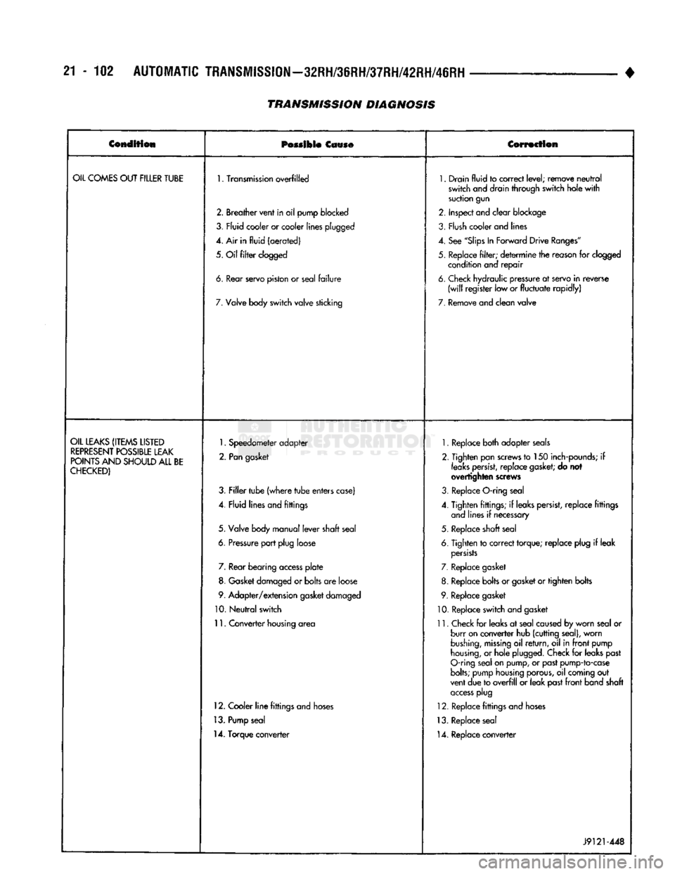
21-102
AUTOMATIC
TRANSMISSION—32RH/36RH/37RH/42RH/46RH
TRANSMISSION
DIAGNOSIS
•
Condition
Possible
Cause Correction
OIL
COMES
OUT
FILLER
TUBE
1.
Transmission
overfilled
1.
Drain
fluid
to
correct
level;
remove
neutral
switch
and drain
through
switch
hole
with
suction
gun
2.
Breather
vent
in
oil
pump
blocked
2.
Inspect
and
clear
blockage
3,
Fly id
cooler
or cooler
lines
plugged
3.
Flush
cooler and lines
4. Air in
fluid
(aerated)
4.
See
"Slips
In
Forward
Drive
Ranges"
5.
Oil
filter
clogged
5.
Replace
filter;
determine
the reason for clogged
condition and
repair
6.
tear
servo
piston
or
seal
failure
6.
Check hydraulic pressure at servo
in
reverse
(will
register
low or
fluctuate
rapidly)
7.
Valve body
switch
valve
sticking
7.
Remove
and
clean
valve
OIL
LEAKS
(ITEMS
LISTED
REPRESENT
POSSIBLE
LEAK
POINTS
AND
SHOULD
ALL
BE
CHECKED)
1.
Speedometer
adapter
2.
Pan
gasket
3.
Filler
tube
(where
tube
enters
case)
4.
Fluid
lines
and
fittings
5.
Valve body
manual
lever
shaft
seal
6.
Pressure
port
plug
loose 7. Rear
bearing
access
plate
8. Gasket damaged or
bolts
are loose
9.
Adapter/extension
gasket damaged
10.
Neutral
switch
11.
Converter
housing area
12. Cooler
line
fittings and hoses
13. Pump seal
14. Torque converter
1.
Replace both adapter seals
2. Tighten pan screws to 150 inch-pounds; if
leaks
persist,
replace
gasket;
do not
overtighten screws
3. Replace O-ring seal
4. Tighten fittings; if leaks persist, replace fittings and lines if necessary
5. Replace shaft seal
6. Tighten to correct torque; replace plug if leak
persists
7. Replace gasket
8. Replace bolts or gasket or tighten bolts
9. Replace gasket
10. Replace switch and gasket
11. Check for leaks at seal caused by worn seal or burr on converter hub (cutting seal), worn
bushing,
missing
oil
return,
oil in
front
pump
housing,
or hole plugged. Check for leaks past
O-ring seal on pump, or past pump-to-case
bolts;
pump housing porous, oil coming out
vent due to
overfill
or leak past
front
band shaft
access
plug
12. Replace fittings and hoses
13. Replace seal 14. Replace converter
J9121-448