1993 DODGE TRUCK headlamp
[x] Cancel search: headlampPage 446 of 1502

•
LAMPS
8L - 3
EXTERIOR
LAMPS
SERWICE PROCEDURES
INDEX
page
Cargo
Lamp
7
Clearance Lamps
for
Dual Wheel Model
........
5
Daytime Running
Light
Module (Canada Only)
... 8
Front
Park
and
Turn Signal Lamp Bulb
4
Headlamp
Adjustment
Using
Alignment
Screen
... 3
Headlamp
Alignment
3
Headlamp
Alignment
Preparation
3
page
Headlamp Switch
4
License
Lamp
............................
7
Sealed
Beam Replacement
4
Side
Marker Lamp
and
Bulb
. 5
Tail,
Stop, Turn Signal, Rear Side Marker
and
Back-Up
Lamps
5
Underhood Lamp
8
HEADLAMP
ALIGNMENT
Headlamps
can be
aligned using
the
screen method
provided
in
this section. Alignment Tool C4466-A
or
equivalent
can
also
be
used. Refer
to
instructions
provided with
the
tool
for
proper procedures.
The
preferred headlamp alignment setting
is 0 for
the left/right adjustment
and
1" down
for the up/
down adjustment.
HEADLAMP
ALIGNMENT PREPARATION
(1) Verify headlamp dimmer switch
and
high beam
indicator operation. (2) Correct defective components that could hinder
proper headlamp alignment. (3) Verify proper tire inflation. (4) Clean headlamp lenses.
(5) Verify that luggage area
is not
heavily loaded.
(6) Fuel tank should
be
FULL.
Add 2.94 kg (6.5
lbs.)
of
weight over
the
fuel tank
for
each estimated
gallon
of
missing fuel.
HEADLAMP
ADJUSTMENT USING ALIGNMENT
SCREEN
ALIGNMENT SCREEN PREPARATION (1) Position vehicle
on a
level surface perpendicu
lar
to a
flat wall
7.62
meters
(25 ft)
away from front
of headlamp lens.
(2)
If
necessary, tape
a
line
on the
floor
7.62
meters
(25 ft)
away from
and
parallel
to the
wall.
CENTER
OF
VEHICLE
TO
CENTER
OF
HEADLAMP
LENS
VEHICLE
CENTERLINE" LOW BEAM
HOT
SPOT AREA FLOOR
TO
CENTER
OF
HEADLAMP
LENS
PREFERRED
HOT SPOT
LOCATION
7.62
METERS
(25
FEET)
FRONT
OF
HEADLAMP
938L-25X
Fig.
1 Headlamp
Alignment
Screen
—Typical
Page 447 of 1502
8L
- 4
LAMPS
• (3) Up 1.27 meters (5 feet) from the floor, tape a
line on the wall at the centerline of the vehicle.
Sight along the centerline of the vehicle (from rear of
vehicle forward) to verify accuracy of the line place
ment.
(4) Rock vehicle side-to-side three times to allow
suspension to stabilize. (5) Jounce front suspension three times by pushing
downward on front bumper and releasing. (6) Measure the distance from the center of head
lamp lens to the floor. Transfer measurement to the alignment screen (with tape). Use this line for up/
down adjustment reference.
(7) Measure distance from the centerline of the ve
hicle to the center of each headlamp being aligned. Transfer measurements to screen (with tape) to each side of vehicle centerline. Use these lines for left/
right adjustment reference.
HEADLAMP
ADJUSTMENT
A properly aimed low beam headlamp will project
top edge of high intensity pattern on screen from 50 mm (2 in.) above to 50 mm (2 in.) below headlamp
centerline. The side-to-side outboard edge of high in
tensity pattern should be from 50 mm (2 in.) left to 50 mm (2 in.) right of headlamp centerline (Fig. 1).
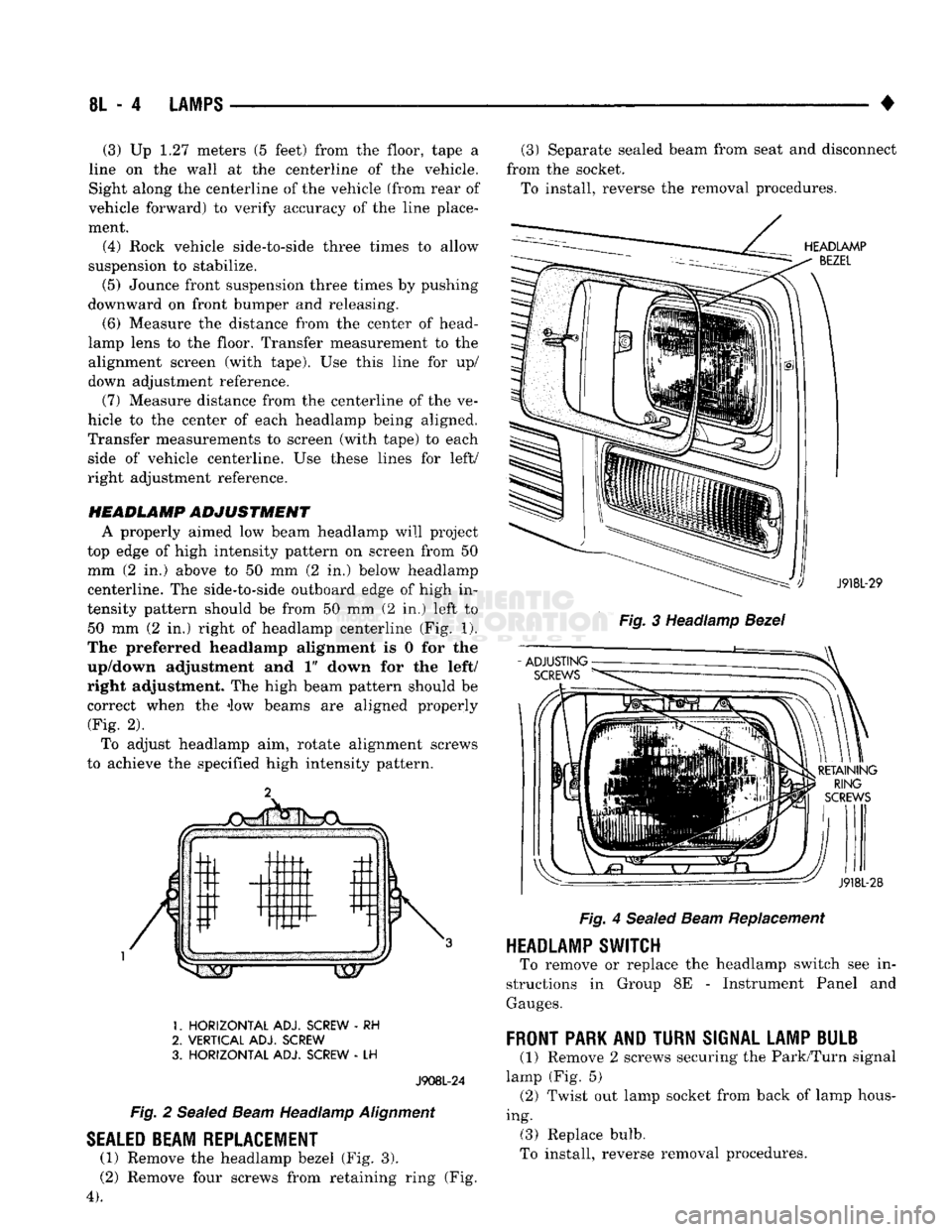
The preferred headlamp alignment is 0 for the
up/down adjustment and 1" down for the left/
right adjustment. The high beam pattern should be correct when the iow beams are aligned properly (Fig. 2).
To adjust headlamp aim, rotate alignment screws
to achieve the specified high intensity pattern.
1.
HORIZONTAL
ADJ. SCREW
- RH
2.
VERTICAL
ADJ. SCREW
3.
HORIZONTAL
ADJ. SCREW
- LH
J908L-24
Fig.
2
Sealed
Beam
Headlamp
Alignment
SEALED
BEAM REPLACEMENT
(1) Remove the headlamp bezel (Fig. 3).
(2) Remove four screws from retaining ring (Fig.
4).
(3) Separate sealed beam from seat and disconnect
from the socket. To install, reverse the removal procedures.
HEADLAMP
BEZEL
: ') J918L-29
Fig.
3 Headlamp
Bezel
RETAINING
RING
SCREWS
J918L-28
Fig.
4
Sealed
Beam
Replacement
HEADLAMP SWITCH
To remove or replace the headlamp switch see in
structions in Group 8E - Instrument Panel and
Gauges.
FRONT
PARK AND
TURN
SIGNAL LAMP BULB
(1) Remove 2 screws securing the Park/Turn signal
lamp (Fig. 5) (2) Twist out lamp socket from back of lamp hous
ing. (3) Replace bulb.
To install, reverse removal procedures.
Page 451 of 1502
8L
- 8
LAMPS
CONNECTOR
CUP
FRONT
LAMP
ASSEMBLY
LICENSE
PLATE
SCREW
LAMP
ASSEMBLY
LICENSE
PLATE
RR8LD24
Fig.
15
License
Plate
Lamps
-
Step
Bumper
TO
TAIL,
STOP,
TURN
SIG. AND
BACK
UP
LAMPS
LICENSE
PLATE
LICENSE
PLATE
LAMP
AND
LAMP
CONNECTOR
BRACKET
ASSEMBLY
J908L-74
Fig.
16
License
Plate
Lamp
Without Rear
Bumper
UNDERHOOD
LAMP
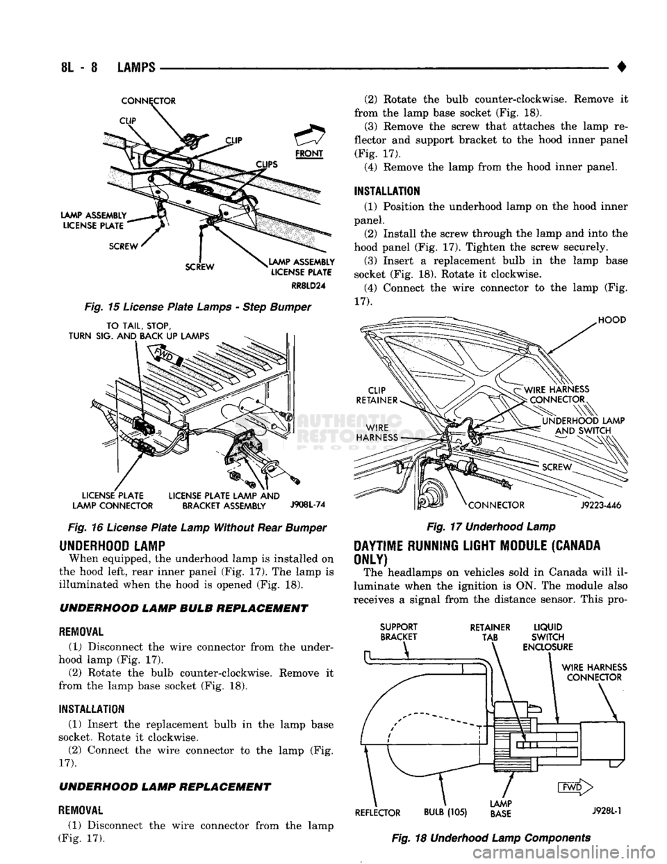
When equipped, the underhood lamp is installed on
the hood left, rear inner panel (Fig, 17). The lamp is
illuminated when the hood is opened (Fig. 18). UNDERHOOD LAMP BULB REPLACEMENT
REMOVAL
(1) Disconnect the wire connector from the under
hood lamp (Fig. 17).
(2) Rotate the bulb counter-clockwise. Remove it
from the lamp base socket (Fig. 18).
INSTALLATION
(1) Insert the replacement bulb in the lamp base
socket. Rotate it clockwise.
(2) Connect the wire connector to the lamp (Fig.
17).
UNDERHOOD LAMP REPLACEMENT
REMOVAL
(1) Disconnect the wire connector from the lamp
(Fig. 17). (2) Rotate the bulb counter-clockwise. Remove it
from the lamp base socket (Fig. 18). (3) Remove the screw that attaches the lamp re
flector and support bracket to the hood inner panel (Fig. 17).
(4) Remove the lamp from the hood inner panel.
INSTALLATION (1) Position the underhood lamp on the hood inner
panel. (2) Install the screw through the lamp and into the
hood panel (Fig. 17). Tighten the screw securely. (3) Insert a replacement bulb in the lamp base
socket (Fig. 18). Rotate it clockwise. (4) Connect the wire connector to the lamp (Fig.
17).
HOOD
J9223-446
Fig.
17
Underhood
Lamp
DAYTIME
RUNNING
LIGHT
MODULE
(CANADA
ONLY)
The headlamps on vehicles sold in Canada will il
luminate when the ignition is ON. The module also
receives a signal from the distance sensor. This pro-
SUPPORT
BRACKET RETAINER
LIQUID
TAB SWITCH
ENCLOSURE
WIRE
HARNESS
CONNECTOR
\
1
d1^—1—l
L/
CMD>
LAMP
REFLECTOR
BULB
(105)
BASE
J9281"1
Fig.
18
Underhood
Lamp
Components
Page 454 of 1502
•
LAMPS
8L - 11
BULB
APPLICATION
GENERAL
INFORMATION
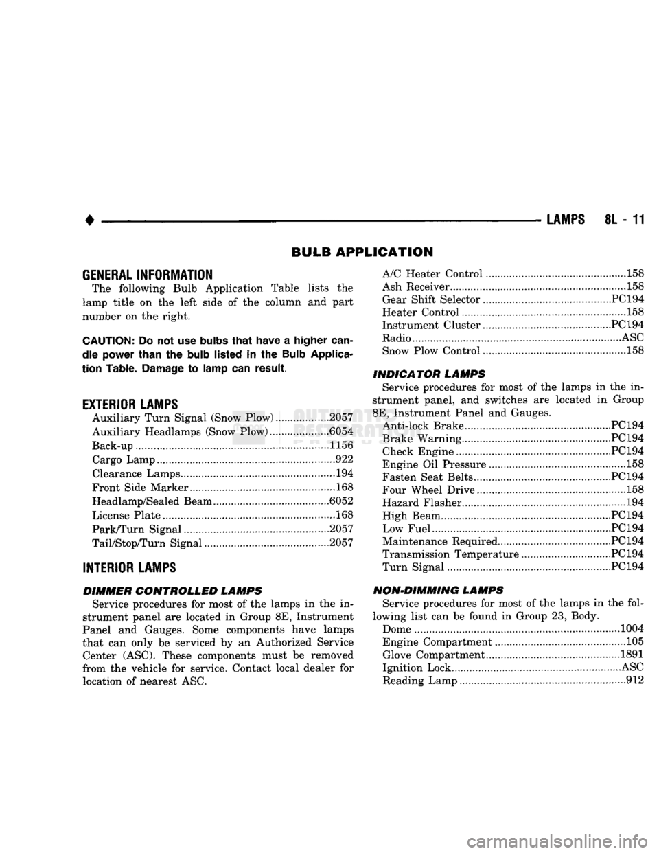
The following Bulb Application Table lists
the
lamp title
on the
left side
of the
column
and
part
number
on the
right.
CAUTION:
Do not use
bulbs
that
have
a
higher
can
dle power than
the
bulb
listed
in the
Bulb
Applica
tion Table.
Damage
to
lamp
can
result.
EXTERIOR LAMPS
Auxiliary Turn Signal (Snow Plow) 2057
Auxiliary Headlamps (Snow Plow) .6054
Back-up....................... .......1156 Cargo Lamp..
922
Clearance Lamps
194
Front Side Marker
168
Headlamp/Sealed Beam .6052
License Plate
168
Park/Turn Signal 2057
TaiyStop/Turn Signal ...2057
INTERIOR LAMPS
DIMMER CONTROLLED LAMPS Service procedures
for
most
of the
lamps
in the in
strument panel
are
located
in
Group
8E,
Instrument
Panel
and
Gauges. Some components have lamps
that
can
only
be
serviced
by an
Authorized Service Center (ASC). These components must
be
removed
from
the
vehicle
for
service. Contact local dealer
for
location
of
nearest
ASC.
A/C Heater Control
158
Ash Receiver
..158
Gear Shift Selector...........................................PC194
Heater Control
158
Instrument Cluster.. PC 194
Radio
ASC
Snow Plow Control
.158
INDICATOR LAMPS Service procedures
for
most
of the
lamps
in the in
strument panel,
and
switches
are
located
in
Group
8E,
Instrument Panel
and
Gauges. Anti-lock Brake PC194
Brake Warning PC194 Check Engine PC194
Engine
Oil
Pressure
158
Fasten Seat Belts.. PC 194 Four Wheel Drive ....158
Hazard Flasher
194
High Beam PC194
Low Fuel....... JPC194
Maintenance Required PC 194
Transmission Temperature ..PC 194 Turn Signal PC194
NON-DIMMING LAMPS Service procedures
for
most
of the
lamps
in the
fol
lowing list
can be
found
in
Group
23,
Body.
Dome
1004
Engine Compartment ...105 Glove Compartment....
1891
Ignition Lock
ASC
Reading Lamp
912
Page 468 of 1502
POWER
MIRRORS
CONTENTS
page
SERVICE PROCEDURES
2
GENERAL
INFORMATION
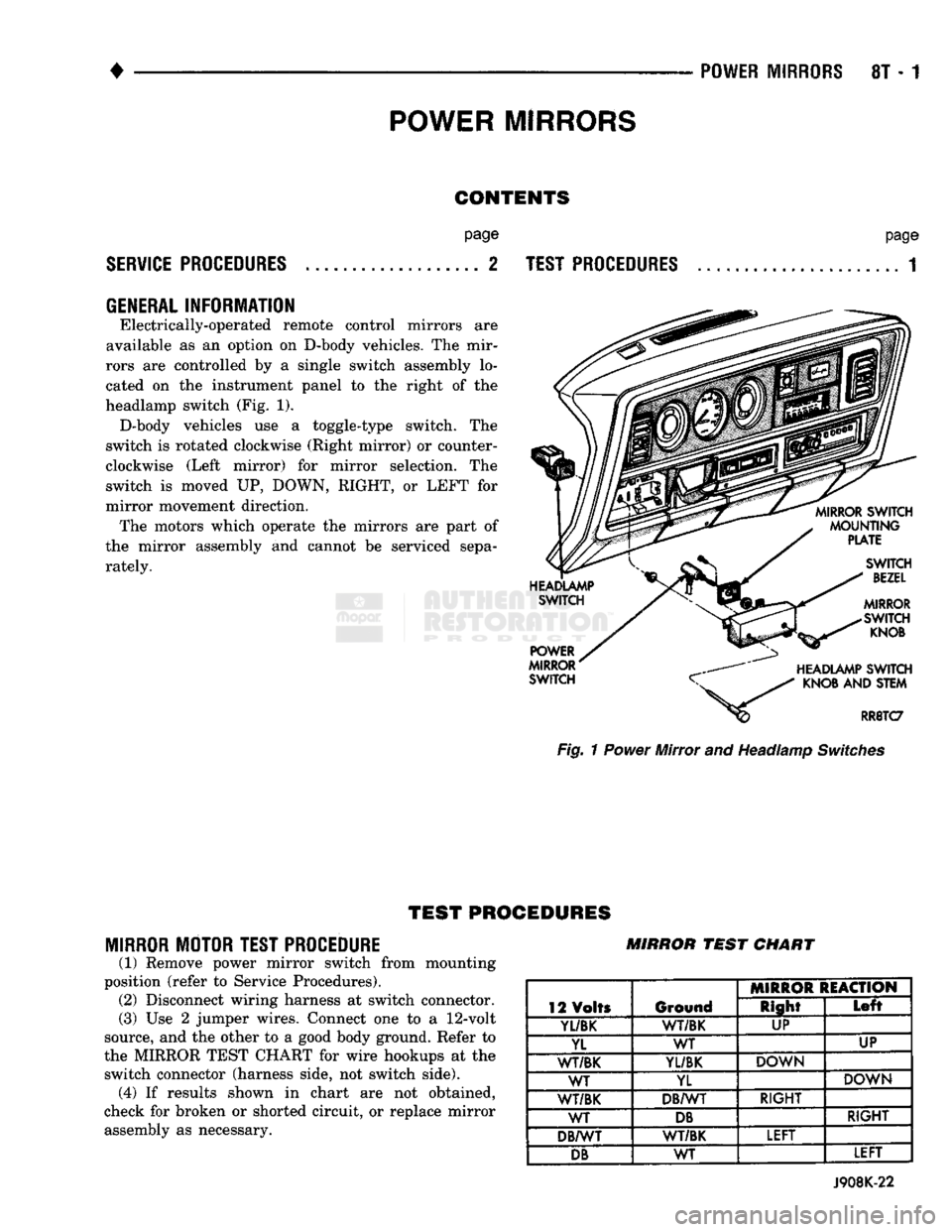
Electrically-operated remote control mirrors are
available as an option on D-body vehicles. The mir
rors are controlled by a single switch assembly lo
cated on the instrument panel to the right of the
headlamp switch (Fig. 1). D-body vehicles use a toggle-type switch. The
switch is rotated clockwise (Right mirror) or counter
clockwise (Left mirror) for mirror selection. The
switch is moved UP, DOWN, RIGHT, or LEFT for
mirror movement direction. The motors which operate the mirrors are part of
the mirror assembly and cannot be serviced sepa
rately.
page
TEST PROCEDURES
...................... 1 Fig. 1 Power Mirror and Headlamp Switches
TEST
PROCEDURES
MIRROR MOTOR TEST PROCEDURE
(1) Remove power mirror switch from mounting
position (refer to Service Procedures). (2) Disconnect wiring harness at switch connector.
(3) Use 2 jumper wires. Connect one to a
12-volt
source, and the other to a good body ground. Refer to
the MIRROR TEST CHART for wire hookups at the switch connector (harness side, not switch side), (4) If results shown in chart are not obtained,
check for broken or shorted circuit, or replace mirror assembly as necessary. MIRROR
TEST
CHART
12 Volts Ground MIRROR REACTION
12 Volts Ground Right
Left
Yl/BK
1
WT/BK UP
YL WT UP
WT/BK
YL/BK
DOWN
WT YL DOWN
WT/BK DB/WT RIGHT
WT
DB
RIGHT
DB/WT WT/BK LEFT
DB
WT LEFT
J908K-22
Page 469 of 1502
8T - 2
POWER MIRRORS
•
MIRROR
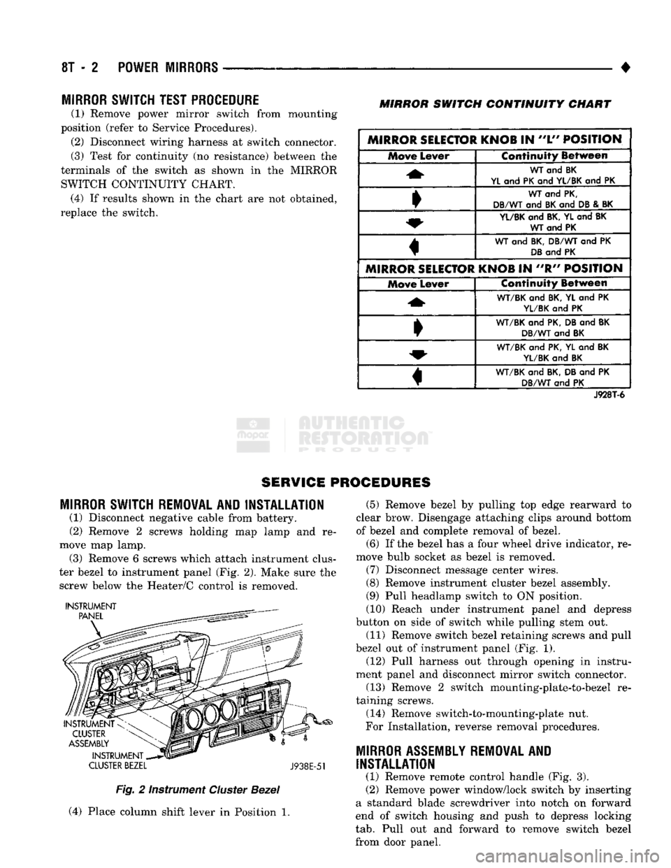
SWITCH TEST PROCEDURE
(1) Remove power mirror switch from mounting
position (refer to Service Procedures). (2) Disconnect wiring harness at switch connector.
(3) Test for continuity (no resistance) between the
terminals of the switch as shown in the MIRROR SWITCH CONTINUITY CHART. (4) If results shown in the chart are not obtained,
replace the switch.
MIRROR
SWITCH
CONTINUITY
CHART
MIRROR SELECTOR KNOB
IN
"L"
POSITION Move
Lever Continuity Between
WT
and BK
YL
and
PK
and
YL/BK
and PK
WT
and
PK,
DB/WT
and
BK
and
DB
&
BK
YL/BK
and
BK, YL
and
BK WT and PK
WT
and
BK, DB/WT
and PK
DB
and
PK
MIRROR SELECTOR KNOB
IN "R"
POSITION Move
Lever Continuity Between
WT/BK
and
BK,
YL and PK
YL/BK
and PK
•
WT/BK
and
PK, DB
and
BK
DB/WT
and
BK
WT/BK
and
PK, YL
and
BK
YL/BK
and
BK
«
WT/BK
and
BK, DB
and PK
DB/WT
and PK
J928T-6
SERVICE PROCEDURES
MIRROR
SWITCH REMOVAL AND INSTALLATION
(1) Disconnect negative cable from battery.
(2) Remove 2 screws holding map lamp and re
move map lamp. (3) Remove 6 screws which attach instrument clus
ter bezel to instrument panel (Fig. 2). Make sure the screw below the Heater/C control is removed.
INSTRUMENT
CLUSTER
BEZEL
J938E-51
Fig.
2 Instrument
Cluster
Bezel
(4) Place column shift lever in Position 1. (5) Remove bezel by pulling top edge rearward to
clear brow. Disengage attaching clips around bottom
of bezel and complete removal of bezel.
(6) If the bezel has a four wheel drive indicator, re
move bulb socket as bezel is removed. (7) Disconnect message center wires.
(8) Remove instrument cluster bezel assembly.
(9) Pull headlamp switch to ON position.
(10) Reach under instrument panel and depress
button on side of switch while pulling stem out.
(11) Remove switch bezel retaining screws and pull
bezel out of instrument panel (Fig. 1). (12) Pull harness out through opening in instru
ment panel and disconnect mirror switch connector.
(13) Remove 2 switch mounting-plate-to-bezel re
taining screws.
(14) Remove switch-to-mounting-plate nut.
For Installation, reverse removal procedures.
MIRROR
ASSEMBLY
REMOVAL
AND
INSTALLATION
(1) Remove remote control handle (Fig. 3).
(2) Remove power window/lock switch by inserting
a standard blade screwdriver into notch on forward
end of switch housing and push to depress locking
tab.
Pull out and forward to remove switch bezel
from door panel.
Page 472 of 1502

-
CHIME/BUZZER WARNING SYSTEMS
8U - 1
CHIME/BUZZER
WARNING SYSTEMS
CONTENTS
page
DIAGNOSIS
GENERAL
INFORMATION
page
1
KEY-IN SWITCH REPLACEMENT
3
1
OPERATION
1
GENERAL
INFORMATION
The buzzer module is located to the right of the
steering column (Fig. 1). The buzzer sounds an audi
ble warning tone in any of the following conditions: • Vehicle lights are ON when the driver's door is
opened.
• The key is in the ignition and the driver's door is
open. • The ignition is switched ON and the driver's seat
belt is not buckled. Buzzer will quit after 4 to 8 sec
onds.
In addition to the buzzer, a seat belt light in
dicator turns on as a reminder to fasten seat belt.
BUZZER
MODULE
INTERMITTENT
WIPE MODULE
Fig, 1 Buzzer Module Location
OPERATION
Battery voltage for module operation is supplied to
two pins. Battery voltage is present at pin 7 at all
times (Figs. 2 and 3). Pin 1 receives voltage when
the ignition switch is turned ON.
SEA T BELT WARNING To sound the seat belt warning, the module needs:
• battery voltage at the ignition switch input (Pin 1)
• a ground at the seat belt switch.
• a ground at Pin 3 to activate the timer. This occurs when the seat belt switch is closed be
cause the driver's seat belt is not buckled. The "fas
ten belt" light will also turn on along with the
warning sound. KEY IN IGNITION
To sound the "key in ignition" alarm, the module
needs:
• the ignition key warning switch must be closed
• the driver's door jamb switch must be closed. These conditions ground pin 6 of the module. These
switches are closed when the driver's door is open
and the key is in the ignition.
LIGHTS ON To sound the "lights on" warning, the module
needs:
• the headlamp switch must be closed
*> the driver's door jamb switch must be closed. These conditions ground pin 6 of the module. These
switches are closed when the driver's door is open
and the headlamp switch is on.
DIAGNOSIS
If the buzzer unit does not operate as described,
check the two fuses for pins 1 and 7 (Figs. 2, 3 and 4) and replace as required. If the fuses are not defec
tive,
perform the following tests to determine if the
problem is in the module or in the wiring. Using a flat blade screwdriver, release the locking plastic clip
while carefully pulling out the module. Plug in a known good module and check its operation. If the
problem is not corrected by replacing the module, re move the module and continue as follows:
VOLTAGE TESTS Ignition in run, measure between the following
pins and vehicle ground.
• Measure voltage at buzzer module connector pin 1.
Meter should read battery voltage. If not, repair open
to ignition switch.
Turn ignition off and remove key from igni
tion.
• Measure voltage at buzzer module connector pin 7.
Meter should read battery voltage. If not, repair open
to fuse. Battery voltage is present at Pin 7 at all
times regardless of key position.
Page 473 of 1502
8U
- 2
CHIME/BUZZER
WARNING SYSTEMS
•
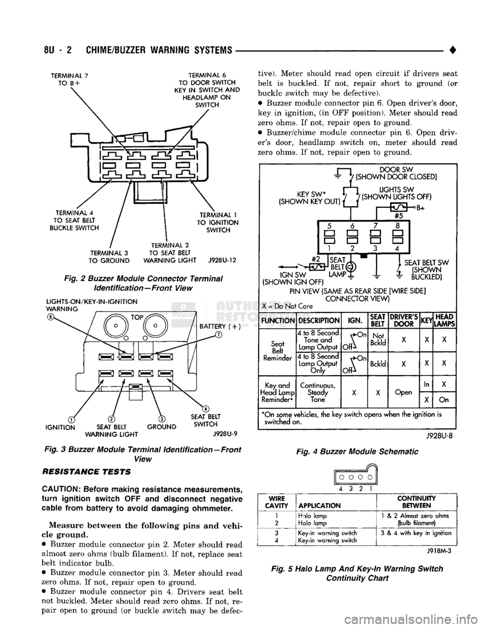
TERMINAL
7
TO
B
+
TERMINAL
6
TO DOOR SWITCH
KEY
IN
SWITCH
AND
HEADLAMP
ON
SWITCH
!cO=f
Mi c£K
*£h
• CZ3
EZZ3
EZI 1
TERMINAL
4
TO SEAT BELT
BUCKLE SWITCH TERMINAL
1
TO
IGNITION
SWITCH
TERMINAL
3
TO GROUND TERMINAL
2
TO SEAT BELT
WARNING
LIGHT
J928U-12
Fig.
2
Buzzer
Module
Connector
Terminal
Identification—Front
View
LIGHTS-ON/KEY-IN-IGNITION
WARNING
BATTERY
(+)
IS SI S K|
IGNITION
SEAT BELT
WARNING
LIGHT
GROUND SEAT BELT
SWITCH
J928U-9
Fig.
3
Buzzer
Module
Terminal
Identification—Front
View RESISTANCE TESTS
CAUTION:
Before making resistance measurements,
turn
ignition switch
OFF and
disconnect negative cable from
battery
to
avoid damaging ohmmeter.
Measure between the following pins and vehi
cle ground.
• Buzzer module connector pin 2. Meter should read almost zero ohms (bulb filament). If not, replace seat
belt indicator bulb.
• Buzzer module connector pin 3. Meter should read
zero ohms. If not, repair open to ground. • Buzzer module connector pin 4. Drivers seat belt
not buckled. Meter should read zero ohms. If not, re
pair open to ground (or buckle switch may be defec
tive).
Meter should read open circuit if drivers seat
belt is buckled. If not, repair short to ground (or buckle switch may be defective).
• Buzzer module connector pin 6. Open driver's door,
key in ignition, (in OFF position). Meter should read
zero ohms. If not, repair open to ground.
• Buzzer/chime module connector pin 6. Open driv
er's door, headlamp switch on, meter should read
zero ohms. If not, repair open to ground.
r—i
DOORSW
±
7
(SHOWN
DOOR
CLOSED)
rFY<;w M
UGHTS
SW
(SHOWN
KEW/
f(SHOWN^JGHTS
OFF)
#5 -^•^Y
BELT(I)
SW
LAMP
JL
SEAT
BELT
SW
/.
(SHOWN
-
BUCKLED)
IGN
SW
(SHOWN
IGN OFF)
PIN
VIEW
(SAME
AS
REAR
SIDE
[WIRE
SIDE]
CONNECTOR
VIEW)
X
=
Do Not Care
FUNCTION
DESCRIPTION
IGN.
SEAT
BELT
DRIVER'S
DOOR
KEY
HEAD
LAMPS
Seat
Belt
Reminder
4
to
8
Second
Tone and
Lamp
Output
^On
OP
Not
Bckld
X
X
X
Seat
Belt
Reminder
4
to
8
Second
Lamp
Output
Only
^On
OfP
Bckld
X X
X
Key
and
Head Lamp Reminder*
Continuous,
Steady
Tone
X
X
Open
In
X
Key
and
Head Lamp Reminder*
Continuous,
Steady
Tone
X
X
Open
X
On
*On
some
vehicles,
the key
switch
opens
when the ignition is switched on.
J928U-8
Fig.
4
Buzzer
Module
Schematic
o
o o o
4 3 2 1
WIRE
CAVITY APPLICATION
CONTINUITY
BETWEEN
1
2
Hdo
lamp
Halo
lamp
1
& 2
Almost
zero
ohms
(bulb
filament)
3
4
Key-in
warning switch
Key-in
warning switch
3
& 4
with
key in ignition
J918M-3
Fig.
5 Halo
Lamp
And
Key-In
Warning
Switch
Continuity Chart