1993 DODGE TRUCK headlamp
[x] Cancel search: headlampPage 603 of 1502
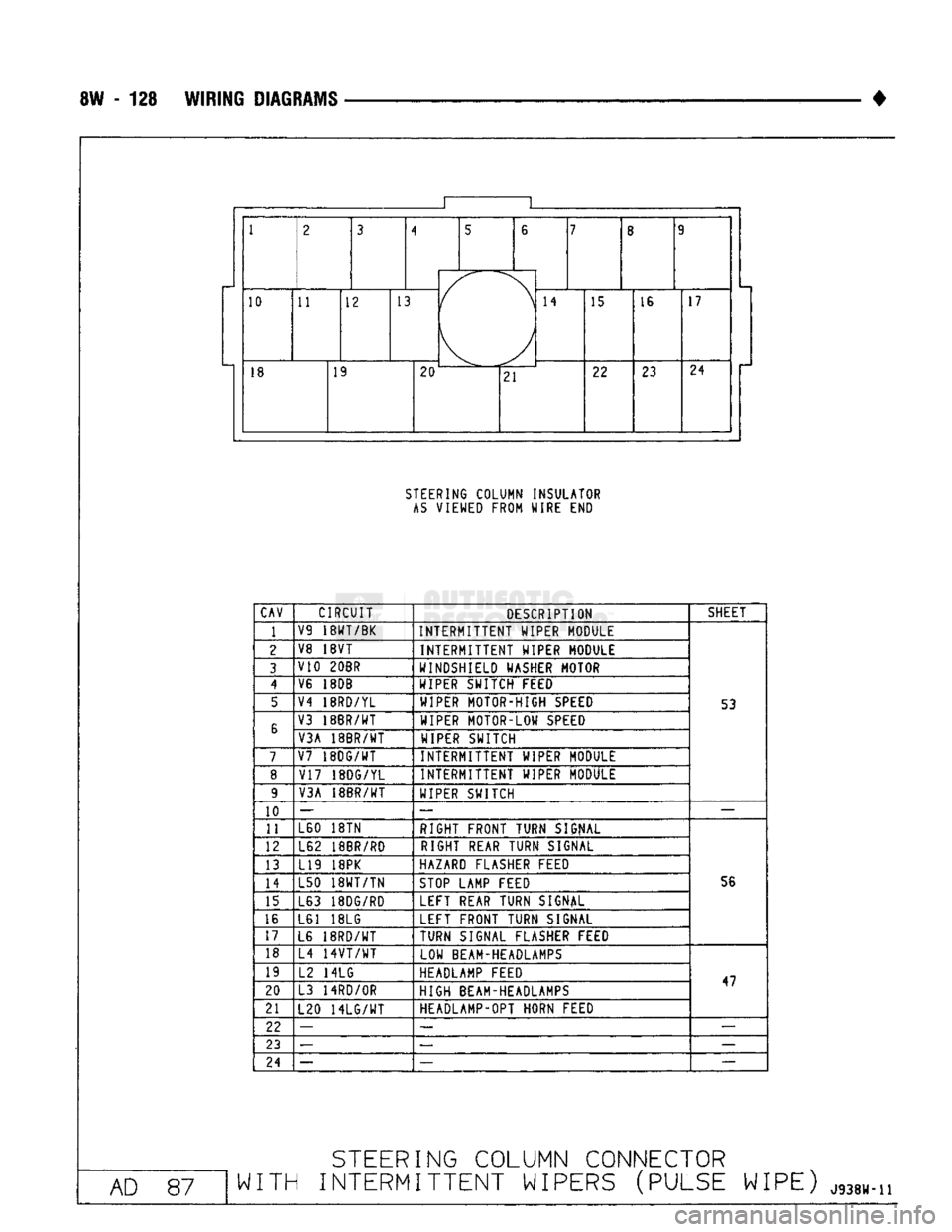
8W - 128 WIRING
DIAGRAMS
• 10
11 12
13
14
15 16 17
18 19
20
21 22
23 24
STEERING
COLUMN INSULATOR
AS
VIEWED FROM WIRE END
CAV
CIRCUIT
DESCRIPTION SHEET
1
V9
18WT/BK
INTERMITTENT WIPER MODULE
2 V8 18VT
INTERMITTENT WIPER MODULE
3 V10 20BR
WINDSHIELD WASHER MOTOR
4 V6 18DB
WIPER SWITCH FEED
5 V4 18RD/YL
WIPER MOTOR-HIGH SPEED
53
6 V3 18BR/WT
WIPER MOTOR-LOW SPEED
6
V3A 18BR/WT WIPER SWITCH
7 V7
18DG/WT
INTERMITTENT WIPER MODULE
8
V17 18DG/YL INTERMITTENT WIPER MODULE
9 V3A 18BR/WT
WIPER SWITCH
10 —
— —
11 L60 18TN
RIGHT FRONT TURN SIGNAL
12 L62 18BR/RD RIGHT REAR TURN SIGNAL
13 L19 18PK HAZARD FLASHER FEED
14 L50
18WT/TN
STOP LAMP FEED 56
15 L63 18DG/RD LEFT REAR TURN SIGNAL
16 L61 18LG LEFT FRONT TURN SIGNAL
17 L6
18RD/WT
TURN SIGNAL FLASHER FEED
18 L4
14VT/WT
LOW BEAM-HEADLAMPS
19 L2 14LG HEADLAMP FEED
47
20 L3
14RD/0R
HIGH BEAM-HEADLAMPS 47
21 L20
14LG/WT
HEADLAMP-OPT HORN FEED
22 —
— —
23 —
—
24 — —-
—
AD
87
STEERING
COLUMN CONNECTOR
WITH
INTERMITTENT WIPERS (PULSE WIPE)
J938W.n
Page 604 of 1502
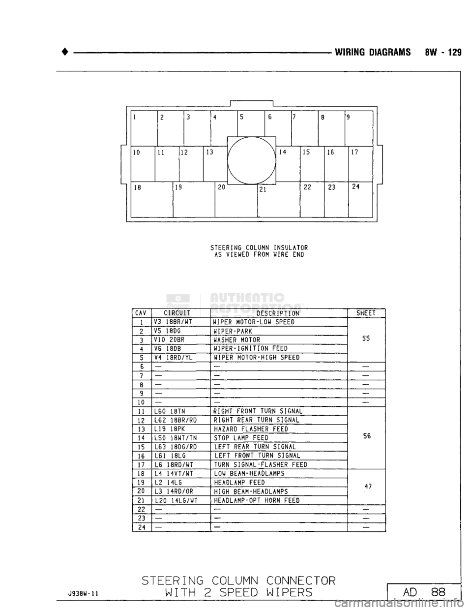
•
WIRING DIAGRAMS 8W - 129 1
1
2 3
4 5
6
7
8 9
1
2 3
(
\ ) 7
8 9
10 11 12 13
(
\ ) 14
15 16 17
18 19
20 ^-— -
21 22
23 24
STEERING COLUMN INSULATOR
AS
VIEWED FROM WIRE END
CAV CIRCUIT
DESCRIPTION SHEET
1
V3
18BR/WT
WIPER MOTOR-LOW SPEED
55
2
V5 18DG
WIPER-PARK
55
3 V10
20BR
WASHER MOTOR 55
4 V6 18DB
WIPER-IGNITION FEED 55
5 V4
18RD/YL
WIPER MOTOR-HIGH SPEED 55
6 —
— —
7 —
— —
8 —
— —
9 —
— —
10 —
— —
11 L60 18TN
RIGHT FRONT TURN SIGNAL
56
12
L62 18BR/RD
RIGHT REAR TURN SIGNAL
56
13
L19 18PK
HAZARD FLASHER FEED
56
14 L50
18WT/TN
STOP LAMP FEED 56
15 L63 18DG/RD
LEFT REAR TURN SIGNAL 56
16 L61 18LG
LEFT FRONT TURN SIGNAL 56
17 L6
18RD/WT
TURN SIGNAL-FLASHER FEED 56
18 L4
14VT/WT
LOW BEAM-HEADLAMPS
47
19
L2 14LG HEADLAMP FEED
47
20 L3 14RD/OR
HIGH BEAM-HEADLAMPS 47
21 L20
14LG/WT
HEADLAMP-OPT HORN FEED 47
22 —
— —
23 —
— —
24 —
—
—
J938H-11
STEERING
COLUMN CONNECTOR
WITH 2
SPEED
WIPERS
AD 88
Page 605 of 1502
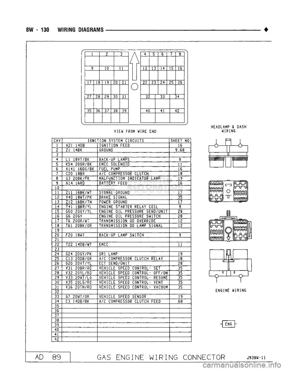
8W - 130
WIRING
DIAGRAMS
•
1 2 3
A 4
5 6
7
8
/
9
10
11
/
12 13
14
15 16
/
17
18
19
20
21
u
22
23
24
25 26
u
27
28 29
30
31
u
32 33
34
u
35 36
37
38 39
u
40
41 42
u
VIEW FROM WIRE
END
HEADLAMP
I
DASH
WIRING
CAV
IGNITION
SYSTEM CIRCUITS
SHEET
NO
1 A21
14DB
IGNITION
FEED 16
2
Zl 14BK
GROUND
9.68
3
4
LI 18VT/BK BACK-UP LAMPS 9
5 K54 200R/BK
EMCC
SOLENOID
11
6 A141 16DG/BK
FUEL PUMP 16
7
C20
18BR
A/C
COMPRESSOR CLUTCH 18
8 G3 20BK/PK MALFUNCTION INDICATOR LAMP 19
9 A14
16RD
BATTERY FEED 16
10
11
Zll
16BK/WT
SIGNAL GROUND
17
12 V40 18WT/PK
BRAKE
SIGNAL 35
13 Z12 16BK/TN
POWER
GROUND
17
14
T41 18BR/YL ENGINE STARTER RELAY COIL 9
15 G60 20GY/YL ENGINE
OIL
PRESSURE
SEND/UNIT 28
16 G6 20GY
ENGINE
OIL
PRESSURE
SWITCH 28
17 T6
200R/WT
TRANSMISSION
OD
OVERRIDE 12
18 T61 20BK/0R
TRANSMISSION
OD
LAMP SIGNAL
12
19
20
F20
18WT
BACK-UP LAMP SWITCH 9
21
22 T22 14DB/WT
EMCC
11
23
24
G24 20GY/PK
SRI
LAMP
19
25 C13 20DB/0R
A/C
COMPRESSOR CLUTCH RELAY
18
26 G20
20VT/YL
ECT SEND/UNIT
28
27
V31 20BR/RD VEHICLE
SPEED
CONTROL-
SET
35
28 V32 20YL/RD VEHICLE
SPEED
CONTROL- OFF/ON
35
29 V33
20WT/LG
VEHICLE
SPEED
CONTROL- RESUME 35
30
V35 20LG/RD VEHICLE
SPEED
CONTROL- VENT
35
31 V36 20TN/RD VEHICLE
SPEED
CONTROL- VACUUM
35
32
33 G7
20WT/0R
VEHICLE
SPEED
SENSOR 19
34
C3 14DB/BK
A/C
COMPRESSOR CLUTCH FEED 68
35
36
37
38
39
40
41
42
&
GjCUQjQ
UXJUXj
O
"IT
mJKXTV
ENGINE WIRING
- ENG
AD
89
GAS
ENGINE WIRING CONNECTOR
J938W-11
Page 799 of 1502
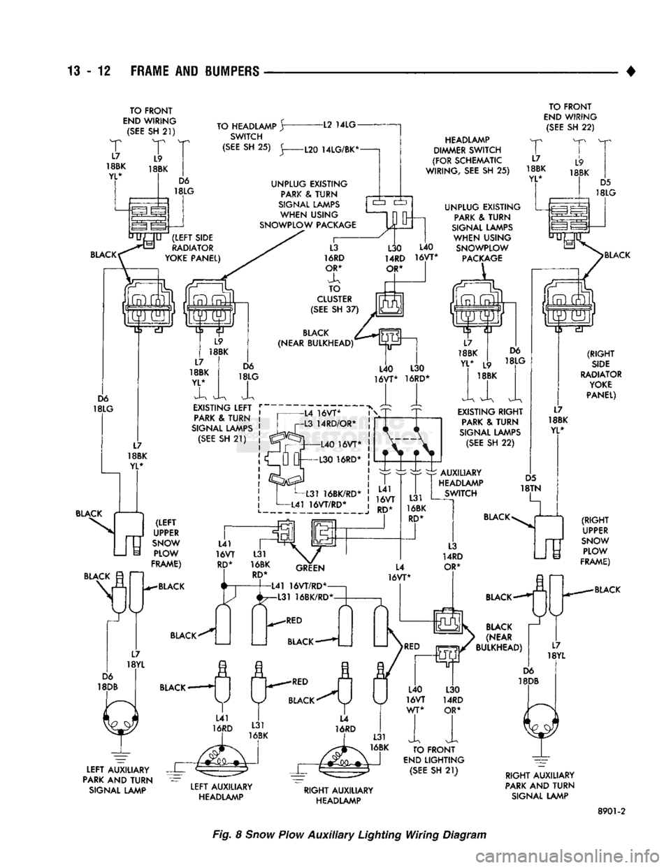
13
- 12
FRAME AND BUMPERS
TO FRONT
END
WIRING
(SEE
SH
21)
T
T
18BK
18BK
YL* TO HEADLAMP
Jr
SWITCH -L2
14LG
TO FRONT
END
WIRING
(SEE
SH
22)
BLACK (RIGHT
SIDE
RADIATOR
YOKE
PANEL) BLACK
(RIGHT
' UPPER
SNOW
PLOW
FRAME)
BLACK
LEFT
AUXILIARY
PARK AND
TURN
SIGNAL LAMP
LEFT
AUXILIARY
HEADLAMP
RIGHT
AUXILIARY
HEADLAMP
RIGHT
AUXILIARY
PARK AND
TURN
SIGNAL LAMP
8901-2
Fig. 8
Snow
Plow
Auxiliary
Lighting Wiring Diagram
Page 805 of 1502
13 - 18
FRAME
AND
BUMPERS
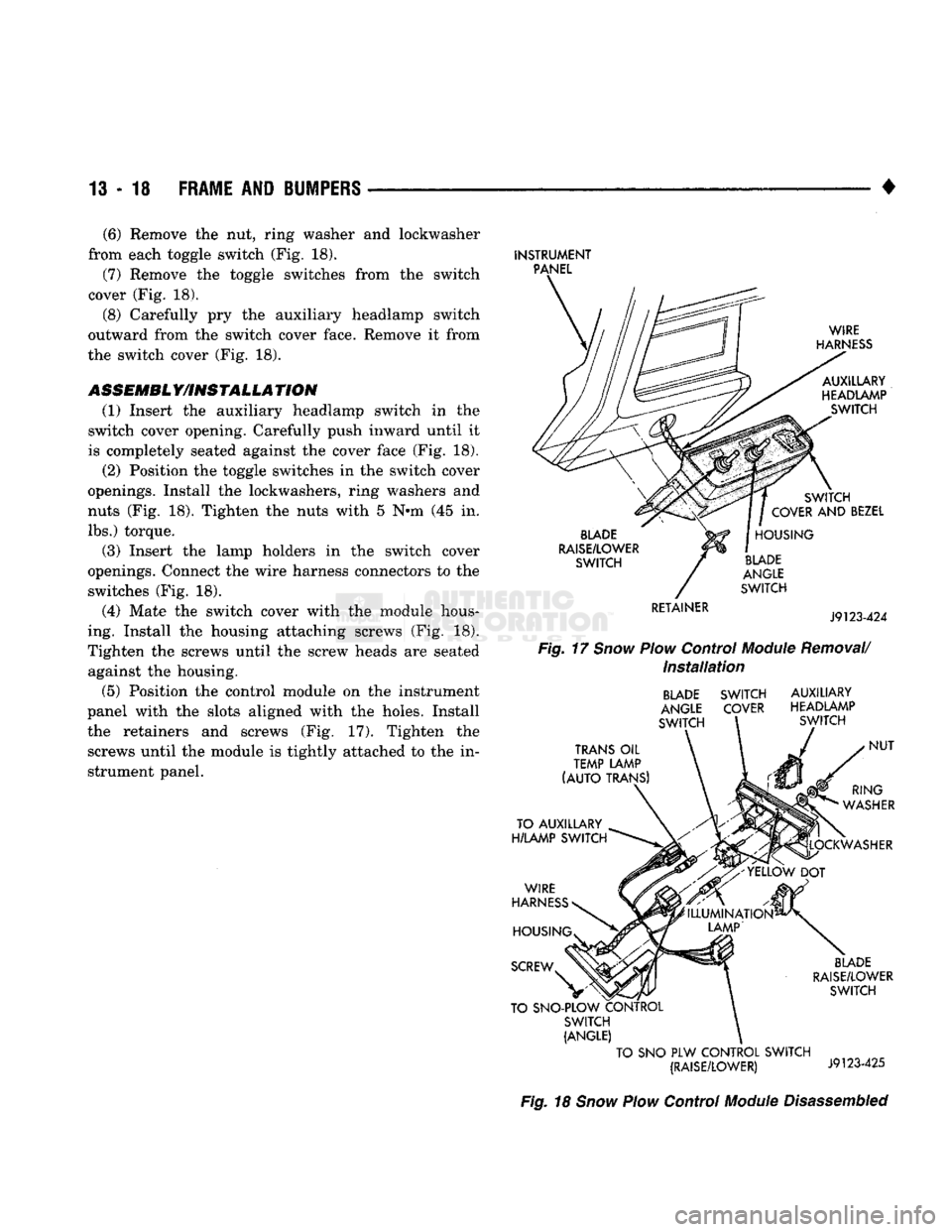
(6) Remove the nut, ring washer and loekwasher
from each toggle switch (Fig. 18).
(7) Remove the toggle switches from the switch
cover (Fig. 18).
(8) Carefully pry the auxiliary headlamp switch
outward from the switch cover face. Remove it from
the switch cover (Fig. 18).
ASSEMBL Y/INSTALLA TION (1) Insert the auxiliary headlamp switch in the
switch cover opening. Carefully push inward until it
is completely seated against the cover face (Fig. 18).
(2) Position the toggle switches in the switch cover
openings. Install the lockwashers, ring washers and
nuts (Fig. 18). Tighten the nuts with 5 Nnn (45 in. lbs.) torque.
(3) Insert the lamp holders in the switch cover
openings. Connect the wire harness connectors to the switches (Fig. 18).
(4) Mate the switch cover with the module hous
ing. Install the housing attaching screws (Fig. 18).
Tighten the screws until the screw heads are seated against the housing.
(5) Position the control module on the instrument
panel with the slots aligned with the holes. Install the retainers and screws (Fig. 17). Tighten the screws until the module is tightly attached to the in
strument panel.
INSTRUMENT
PANEL
WIRE
HARNESS
AUXILLARY
HEADLAMP SWITCH
BLADE
RAISE/LOWER
SWITCH
RETAINER SWITCH
COVER
AND
BEZEL
HOUSING
BLADE
ANGLE
SWITCH
J9123-424
Fig.
17
Snow
Plow
Control
Module
Removal/
Installation
BLADE
SWITCH
ANGLE
COVER
SWITCH AUXILIARY
HEADLAMP SWITCH
TRANS
OIL
TEMP LAMP
(AUTO
TRANS)
TO AUXILLARY
H/LAMP
SWITCH
WIRE
HARNESS
RING
WASHER
LOCKWASHER
HOUSING
SCREW
NUT
'ILLUMINATION*
LAMP'
BLADE
RAISE/LOWER
SWITCH
TO SNO-PLOW CONTROL SWITCH
(ANGLE)
TO
SNO PLW
CONTROL SWITCH (RAISE/LOWER)
J9123-425
Fig.
18
Snow
Plow
Control
Module
Disassembled
Page 1384 of 1502
•
BODY
COMPONENTS
23 - 1
CONTENTS
page
page
CAB/BODY
INTERIOR COMPONENTS
35
FIXED
GLASS
. 29
DOORS
21
PAINT
CODE
CHART
54
EXTERIOR
COMPONENTS
1
REFINISHING
PROCEDURES
54
EXTERIOR COMPONENTS
INDEX
page
Battery
Tray
7
Blower Motor Housing
Insulation
Panel—Diesel
Engine
Only
7
Body
Mouldings, Nameplates
and
Decals .......
9
Cab
. 14
Cab/Body
and
Cargo
Box
Stripes
11
Cargo
Box
19
Cowl
Grille
7
Front
Fenders
8
Fuel
Filler
Door
and
Nozzle/Tubes
12
Grille
and
Grille
Extension Panel
1
Grille
Extension Panel Support Bracket
(With
Diesel Engine Only)
3
page
Grille
Opening Panel (GOP)
and
Radiator Support Panel
3
Hatchgate
and
Components
16
Hood
5
Hood
Inside Release Cable
5
Hood
Latch
4
Labels/Decals/Plates
1
Outside Mirrors
13
Roof
Vent—Ramcharger
. 20
Splash
Shields—Front Fender
9
Sport
Bar
18
Tailgate
14
LABELS/DECALS/PLATES
GENERAL
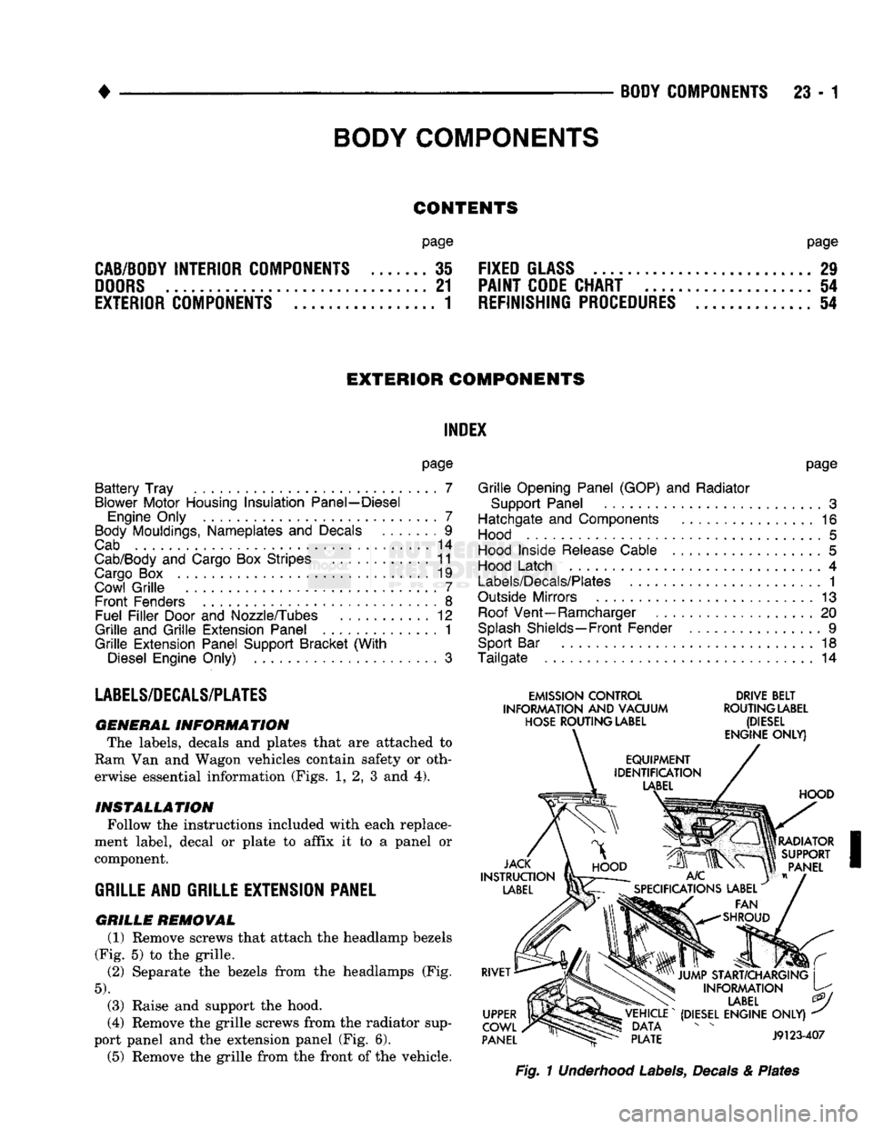
INFORMATION The labels, decals
and
plates that
are
attached
to
Ram Van
and
Wagon vehicles contain safety
or
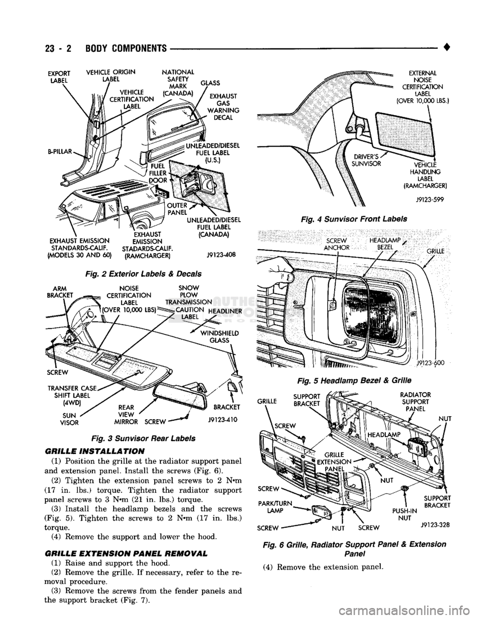
oth erwise essential information (Figs.
1, 2, 3 and 4).
INSTALLATION
Follow the instructions included with each replace
ment label, decal
or
plate
to
affix
it to a
panel
or
component.
GRILLE
AND GRILLE EXTENSION PANEL
GRILLE
REMOVAL (1) Remove screws that attach the headlamp bezels
(Fig.
5) to the
grille.
(2)
Separate
the
bezels from
the
headlamps
(Fig.
5).
(3) Raise
and
support
the
hood.
(4) Remove the grille screws from the radiator sup
port panel
and the
extension panel (Fig.
6).
(5) Remove
the
grille from the front
of
the vehicle.
EMISSION
CONTROL
DRIVE
BELT
INFORMATION
AND
VACUUM
ROUTING
LABEL
HOSE
ROUTING
LABEL
(DIESEL
Fig.
1 Underhood Labels, Decals & Plates
BODY
COMPONENTS
Page 1385 of 1502
23
- 2
BODY COMPONENTS
•
EXPORT
LABEL
VEHICLE ORIGIN
LABEL
NATIONAL
SAFETY MARK
(CANADA) B-PILLAR
GLASS
EXHAUST
GAS
WARNING DECAL
UNLEADED/DIESEL FUEL LABEL
(U.S.)
EXHAUST EMISSION STANDARDS-CALIF.
(MODELS
30 AND 60)
EXHAUST
EMISSION
STADARDS-CALIF. (RAMCHARGER) UNLEADED/DIESEL
FUEL LABEL (CANADA)
J9123-408
Fig.
2
Exterior
Labels
&
Decals
ARM
BRACKET
NOISE
CERTIFICATION
LABEL
UOVER
10,000
LBS)5 SNOW
PLOW
TRANSMISSION
CAUTION HEADLINER
LABEL
TRANSFER
CASE
SHIFT
LABEL
(4WD)
SUN
VISOR
REAR
VIEW
MIRROR SCREW
*
BRACKET
J9123-410
Fig.
3
Sunvisor
Rear
Labels
GRILLE INSTALLATION
(1) Position
the
grille
at the
radiator support panel
and extension panel. Install
the
screws
(Fig. 6).
(2) Tighten
the
extension panel screws
to 2 N»m
(17
in. lbs.)
torque. Tighten
the
radiator support
panel screws
to 3 Nnn (21 in. lbs.)
torque. (3) Install
the
headlamp bezels
and the
screws
(Fig.
5).
Tighten
the
screws
to 2 Nnn (17 in. lbs.)
torque. (4) Remove
the
support
and
lower
the
hood.
GRILLE EMTENSION PANEL REMOVAL (1) Raise
and
support
the
hood.
(2) Remove
the
grille.
If
necessary, refer
to the re
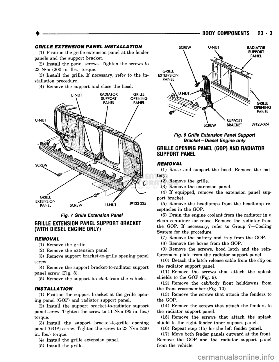
moval procedure. (3) Remove
the
screws from
the
fender panels
and
the support bracket
(Fig. 7).
EXTERNAL
NOISE
CERTIFICATION
LABEL
(OVER
10,000
LBS.)
VEHICLE
HANDLING
LABEL
(RAMCHARGER)
J9123-599
Fig.
4
Sunvisor
Front
Labels
SCREW
ANCHOR
HEADIAMP
BEZEL
•
GRILLE
J9123-600
Fig.
5
Headlamp
Bezel
&
Grille
GRILLE RADIATOR
SUPPORT PANEL
NUT
PUSH-IN
NUT
SCREW
NUT
SCREW SUPPORT
BRACKET
J9123-328
Fig.
6
Grille,
Radiator
Support Panel
&
Extension
Panel
(4) Remove
the
extension panel.
Page 1386 of 1502
•
BODY
COMPONENTS
23 - 3
GRILLE
EXTENSION
PANEL
INSTALLATION
(1) Position the grille extension panel at the fender
panels and the support bracket. (2) Install the panel screws. Tighten the screws to
23 N*m (200 in. lbs.) torque.
(3) Install the grille. If necessary, refer to the in
stallation procedure. (4) Remove the support and close the hood.
U-NUT
RADIATOR GRILLE
Fig. 7 Grille Extension Panel
GRILLE EXTENSION PANEL SUPPORT BRACKET
(WITH
DIESEL ENGINE ONLY)
REMOWAL
(1) Remove the grille.
(2) Remove the extension panel.
(3) Remove support bracket-to-grille opening panel
screw. (4) Remove the support bracket-to-radiator support
panel screw (Fig. 8). (5) Remove the support bracket from the vehicle.
INSTALLATION
(1) Position the support bracket at the grille open
ing panel (GOP) and radiator support panel. (2) Install the support bracket-to-radiator support
panel screw. Tighten the screw to 11 N*m (95 in. lbs.) torque.
(3) Install the support bracket-to-grille opening
panel (GOP) screw. Tighten the screw to 23 N-m (200 in. lbs.) torque.
(4) Install the grille extension panel.
(5) Install the grille.
SCREW
U-NUT
RADIATOR
Fig. 8 Grille Extension Panel Support Bracket—Diesel Engine only
GRILLE OPENING PANEL
(GOP) AND
RADIATOR
SUPPORT
PANEL
REMOVAL
(1) Raise and support the hood. Remove the bat
tery. (2) Remove the grille.
(3) Remove the extension panel.
(4) If equipped, remove the extension panel sup
port bracket.
(5) Remove the headlamps from the headlamp re
ceptacles in the GOP.
(6) Drain the engine coolant from the radiator in a
clean container for reuse. Remove the radiator from
the GOP. If necessary, refer to Group 7—Cooling System for the procedure.
(7) Remove the battery and tray from the GOP.
(8) Remove the horns from the GOP.
(9) Remove the screws, hood latch and the rein
forcement plate from the radiator support panel. (10) Detach the latch release cable from the clip on
the radiator support panel.
(11) Remove the screws that attach the splash
shields to the GOP (Fig. 9). (12) Remove the cab/body front holddowns from
the front crossmember (Fig. 10). (13) Remove the screws that attach the fenders to
the GOP.
(14) Remove the screws that attach the fenders to
the radiator support panel.
(15) Remove the screws that attach the splash
shield to the right fender inner support panel.
(16) Repeat step (15) for the left fender panel.
(17) Move both fender panels outward at the front.
Remove the GOP and the radiator support panel
from the vehicle.