1993 DODGE TRUCK bolt pattern
[x] Cancel search: bolt patternPage 1276 of 1502

•
BAND BAND
Fig.
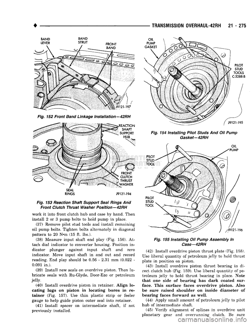
152 Front
Band
Linkage
Installation—42RH
SEAL
RINGS
J9121-194
Fig.
153 Reaction Shaft
Support
Seal
Rings
And Front
Clutch
Thrust
Washer
Position—42RH
work it into front clutch hub and case by hand. Then
install 2 or 3 pump bolts to hold pump in place. (37) Remove pilot stud tools arid install remaining
oil pump bolts. Tighten bolts alternately in diagonal
pattern to 20 N*m (15 ft. lbs.).
(38) Measure input shaft end play (Fig. 156). At
tach dial indicator to converter housing. Position in dicator plunger against input shaft and zero indicator. Move input shaft in and out and record
reading. End play should be 0.56 - 2.31 mm (0.022 - 0.091 in.).
(39) Install new seals on overdrive piston. Then lu
bricate seals with Ru-Glyde, Door-Eze or petroleum
jelly. (40) Install overdrive piston in retainer. Align lo
cating lugs on piston in locating bores in re
tainer (Fig. 157). Use thin plastic strip or feeler gauge to help guide piston outer seal into retainer. (41) Install spacer on intermediate shaft, if not
previously installed.
TRANSMISSION
0VERHAUL-42RH
21 - 275
Fig.
154 Installing Pilot
Studs
And Oil
Pump
Gasket-42RH
Fig.
155 Installing Oil
Pump
Assembly
In
Case—42RH
(42) Install overdrive piston thrust plate (Fig. 158).
Use liberal quantity of petroleum jelly to hold thrust
plate in position on piston. (43) Install overdrive piston thrust bearing in di
rect clutch hub (Fig. 159). Use liberal quantity of pe
troleum jelly to hold thrust bearing in place. Note
that one side of bearing has dark coated sur
face. This surface faces overdrive piston. Also
be sure raised shoulder on inside diameter of
bearing faces forward as well.
(44) Apply small amount of petroleum jelly to pilot
hub of intermediate shaft.
(45) Verify alignment of splines in overdrive unit
planetary gear and overrunning clutch. Be sure
Page 1278 of 1502

•
TRANSMISSION
OVERHAUL-42RH
21 - 277 (47) Lubricate intermediate shaft splines and bushing
surfaces with transmission fluid or petroleum jelly.
(48) Install overdrive unit. Be sure governor tubes
are aligned with feed holes in piston retainer boss. Note that intermediate shaft is snug fit in overdrive
planetary gear and overrunning clutch. If overdrive unit will not seat fully, rotate overdrive output shaft slightly to align splines and try again.
(49) Apply 1-2 drops of Mopar thread adhesive (or
Loctite 242) to overdrive unit attaching bolts. Then install and tighten bolts to 34 N« (25 ft. lbs.) torque.
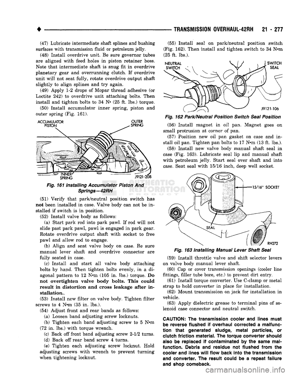
(50) Install accumulator inner spring, piston and
outer spring (Fig. 161).
ACCUMULATOR
OUTER
Fig.
161 Installing
Accumulator
Piston
And
Springs—42RH
(51) Verify that park/neutral position switch has
not been installed in case. Valve body can not be in stalled if switch is in position.
(52) Install valve body as follows: (a) Start park rod into park pawl. If rod will not
slide past park pawl, pawl is engaged in park gear.
Rotate overdrive output shaft with socket to free
pawl and allow rod to engage.
(b) Align and seat valve body on case. Be sure
manual lever shaft and overdrive connector are
fully seated in case.
(c) Install and start all valve body attaching
bolts by hand. Then tighten bolts evenly, in a di agonal pattern to 12 N»m (105 in. lbs.) torque. Do
not overtighten valve body bolts. This could
result in distortion and cross leakage after in stallation..
(53) Install new filter on valve body. Tighten filter
screws to 4 N*m (35 in. lbs.).
(54) Adjust front and rear bands as follows: (a) Loosen band adjusting screw locknuts.
(b) Tighten each band adjusting screw to 5 Nnn
(72 in. lbs.) with torque wrench.
(c) Back off front band adjusting screw 2-1/2 turns.
(d) Back off rear band screw 4 turns.
(e) Tighten each adjusting screw locknut. Hold
adjusting screws with wrench to prevent turning
when tightening locknut. (55) Install seal on park/neutral position switch
(Fig. 162). Then install and tighten switch to 34 N«m
(25 ft. lbs.).
Fig.
162 Park/Neutral Position
Switch
Seal
Position
(56) Install magnet in oil pan. Magnet goes on
small protrusion at corner of pan. (57) Position new oil pan gasket on case and in
stall oil pan. Tighten pan bolts to 17 N*m (13 ft. lbs.).
(58) Install new valve body manual shaft seal in
case (Fig. 163). Lubricate seal lip and manual shaft
with petroleum jelly. Start seal over shaft and into
case.
Seat seal with 15/16 inch, deep well socket.
(59) Install throttle valve and shift selector levers
on valve body manual lever shaft. (60) Cap or cover transmission openings (cooler line
fittings, filler tube bore, etc.) to prevent dirt entry.
(61) Install torque converter. Use C-clamp or metal
strap to hold converter in place for installation. (62) Mount transmission on jack for installation in
vehicle.
(63) Apply dielectric grease to terminal pins of so
lenoid case connector and neutral switch.
CAUTION:
The
transmission
cooler
and
lines
must
be
reverse
flushed
if
overhaul
corrected
a
malfunc
tion
that
generated
sludge,
metal
particles,
or
clutch
friction
material.
The
torque
converter
should
also
be replaced if
contaminated
by the
same
mal
function.
Debris and
residue
not
flushed
from
the
cooler
and
lines
will
flow
back
into
the
transmission
and
converter.
The
result
could
be a
repeat
failure
and
shop
comeback.
Page 1323 of 1502

21
- 322
TRANSMISSION
OVERHAUL-46RH
•
J932M33
Fig.
155
Checking
Alignment
Of Overdrive Planetary
Gear
And Overrunning
Clutch
Splines—46RH
(44) Carefully withdraw alignment tool from over
drive unit.
(45) Lubricate intermediate shaft splines and
bushing surfaces with transmission fluid or petro leum jelly.
(46) Install overdrive unit. Be sure governor tubes
are aligned with feed holes in piston retainer boss.
Intermediate shaft is snug fit in overdrive planetary
gear and overrunning clutch. If overdrive unit will
not seat fully, rotate overdrive output shaft slightly
to align splines and try again.
(47) Apply 1-2 drops of Mopar thread adhesive (or
Loctite 242) to overdrive unit attaching bolts. Then
install and tighten bolts to 34 N» (25 ft. lbs.) torque.
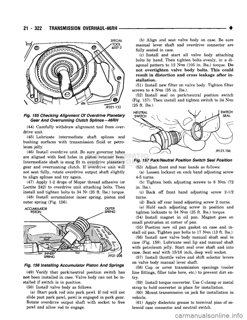
(48) Install accumulator inner spring, piston and
outer spring (Fig. 156).
ACCUMULATOR
OUTER
Fig.
156 Installing
Accumulator
Piston
And
Springs
(49) Verify that park/neutral position switch has
not been installed in case. Valve body can not be in stalled if switch is in position.
(50) Install valve body as follows: (a) Start park rod into park pawl. If rod will not
slide past park pawl, pawl is engaged in park gear.
Rotate overdrive output shaft with socket to free
pawl and allow rod to engage. (b) Align and seat valve body on case. Be sure
manual lever shaft and overdrive connector are
fully seated in case.
(c) Install and start all valve body attaching
bolts by hand. Then tighten bolts evenly, in a di agonal pattern to 12 Nnn (105 in. lbs.) torque. Do
not overtighten valve body bolts. This could result in distortion and cross leakage after in stallation..
(51) Install new filter on valve body. Tighten filter
screws to 4 Nnn (35 in. lbs.).
(52) Install seal on park/neutral position switch
(Fig. 157). Then install and tighten switch to 34 Nnn
(25 ft. lbs.).
Fig.
157 Park/Neutral Position
Switch
Seal
Position
(53) Adjust front and rear bands as follows:
(a) Loosen locknut on each band adjusting screw
4-5 turns.
(b) Tighten both adjusting screws to 8 Nnn (72
in. lbs.).
(c) Back off front band adjusting screw 2-1/2
turns.
(d) Back off rear band adjusting screw 2 turns.
(e) Hold each adjusting screw in position and
tighten locknuts to 34 Nnn (25 ft. lbs.) torque.
(54) Install magnet in oil pan. Magnet goes on
small protrusion at corner of pan.
(55) Position new oil pan gasket on case and in
stall oil pan. Tighten pan bolts to 17 Nnn (13 ft. lbs.).
(56) Install new valve body manual shaft seal in
case (Fig. 158). Lubricate seal lip and manual shaft
with petroleum jelly. Start seal over shaft and into
case.
Seat seal with 15/16 inch, deep well socket.
(57) Install throttle valve and shift selector levers
on valve body manual lever shaft. (58) Cap or cover transmission openings (cooler
line fittings, filler tube bore, etc.) to prevent dirt en
try.
(59) Install torque converter. Use C-clamp or metal
strap to hold converter in place for installation. (60) Mount transmission on jack for installation in
vehicle.
(61) Apply dielectric grease to terminal pins of so
lenoid case connector and neutral switch.
Page 1376 of 1502

•
WHEELS
AND
TIRES
22 - 7 move and install dual rear wheels only when the
proper wrench is available.
INSTALLATION
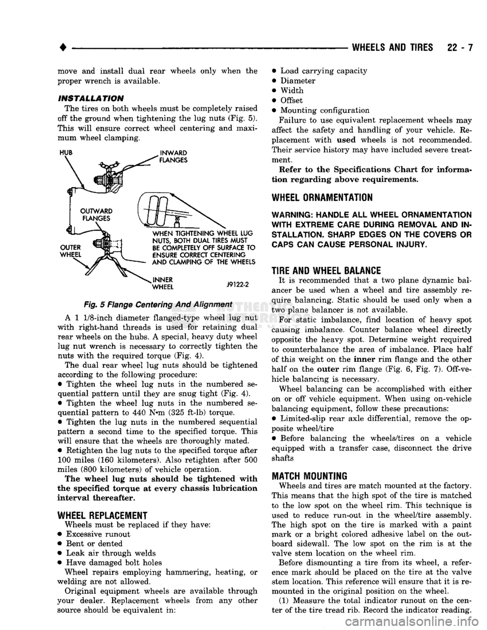
The tires on both wheels must be completely raised
off the ground when tightening the lug nuts (Fig. 5).
This will ensure correct wheel centering and maxi mum wheel clamping.
HUB
^
INWARD
Fig.
5 Flange Centering And
Alignment
A 1
1/8-inch
diameter flanged-type wheel lug nut
with right-hand threads is used for retaining dual rear wheels on the hubs. A special, heavy duty wheel lug nut wrench is necessary to correctly tighten the nuts with the required torque (Fig. 4).
The dual rear wheel lug nuts should be tightened
according to the following procedure:
• Tighten the wheel lug nuts in the numbered se
quential pattern until they are snug tight (Fig. 4).
• Tighten the wheel lug nuts in the numbered se
quential pattern to 440 N#m (325 ft-lb) torque.
• Tighten the lug nuts in the numbered sequential
pattern a second time to the specified torque. This will ensure that the wheels are thoroughly mated. • Retighten the lug nuts to the specified torque after 100 miles (160 kilometers). Also retighten after 500
miles (800 kilometers) of vehicle operation.
The wheel lug nuts should be tightened with
the specified torque at every chassis lubrication
interval thereafter.
WHEEL REPLACEMENT
Wheels must be replaced if they have:
• Excessive runout
• Bent or dented
• Leak air through welds
• Have damaged bolt holes Wheel repairs employing hammering, heating, or
welding are not allowed. Original equipment wheels are available through
your dealer. Replacement wheels from any other source should be equivalent in: • Load carrying capacity
• Diameter
® Width
• Offset
• Mounting configuration
Failure to use equivalent replacement wheels may
affect the safety and handling of your vehicle. Re
placement with used wheels is not recommended.
Their service history may have included severe treat ment.
Refer to the Specifications Chart for informa
tion regarding above requirements.
WHEEL ORNAMENTATION
WARNING; HANDLE
ALL
WHEEL ORNAMENTATION
WITH
EXTREME CARE DURING REMOVAL
AND IN
STALLATION. SHARP EDGES
ON THE
COVERS
OR
CAPS
CAN
CAUSE PERSONAL INJURY.
TIRE AND WHEEL BALANCE
It is recommended that a two plane dynamic bal
ancer be used when a wheel and tire assembly re
quire balancing. Static should be used only when a
two plane balancer is not available. For static imbalance, find location of heavy spot
causing imbalance. Counter balance wheel directly
opposite the heavy spot. Determine weight required
to counterbalance the area of imbalance. Place half of this weight on the inner rim flange and the other
half on the outer rim flange (Fig. 6, Fig. 7). Off-ve
hicle balancing is necessary. Wheel balancing can be accomplished with either
on or off vehicle equipment. When using on-vehicle
balancing equipment, follow these precautions: • Limited-slip rear axle differential, remove the op
posite wheel/tire • Before balancing the wheels/tires on a vehicle
equipped with a transfer case, disconnect the drive shafts
MATCH
MOUNTING
Wheels and tires are match mounted at the factory.
This means that the high spot of the tire is matched
to the low spot on the wheel rim. This technique is used to reduce run-out in the wheel/tire assembly.
The high spot on the tire is marked with a paint mark or a bright colored adhesive label on the out
board sidewall. The low spot on the rim is at the
valve stem location on the wheel rim. Before dismounting a tire from its wheel, a refer
ence mark should be placed on the tire at the valve stem location. This reference will ensure that it is re
mounted in the original position on the wheel. (1) Measure the total indicator runout on the cen
ter of the tire tread rib. Record the indicator reading.