1993 DODGE TRUCK bolt pattern
[x] Cancel search: bolt patternPage 259 of 1502
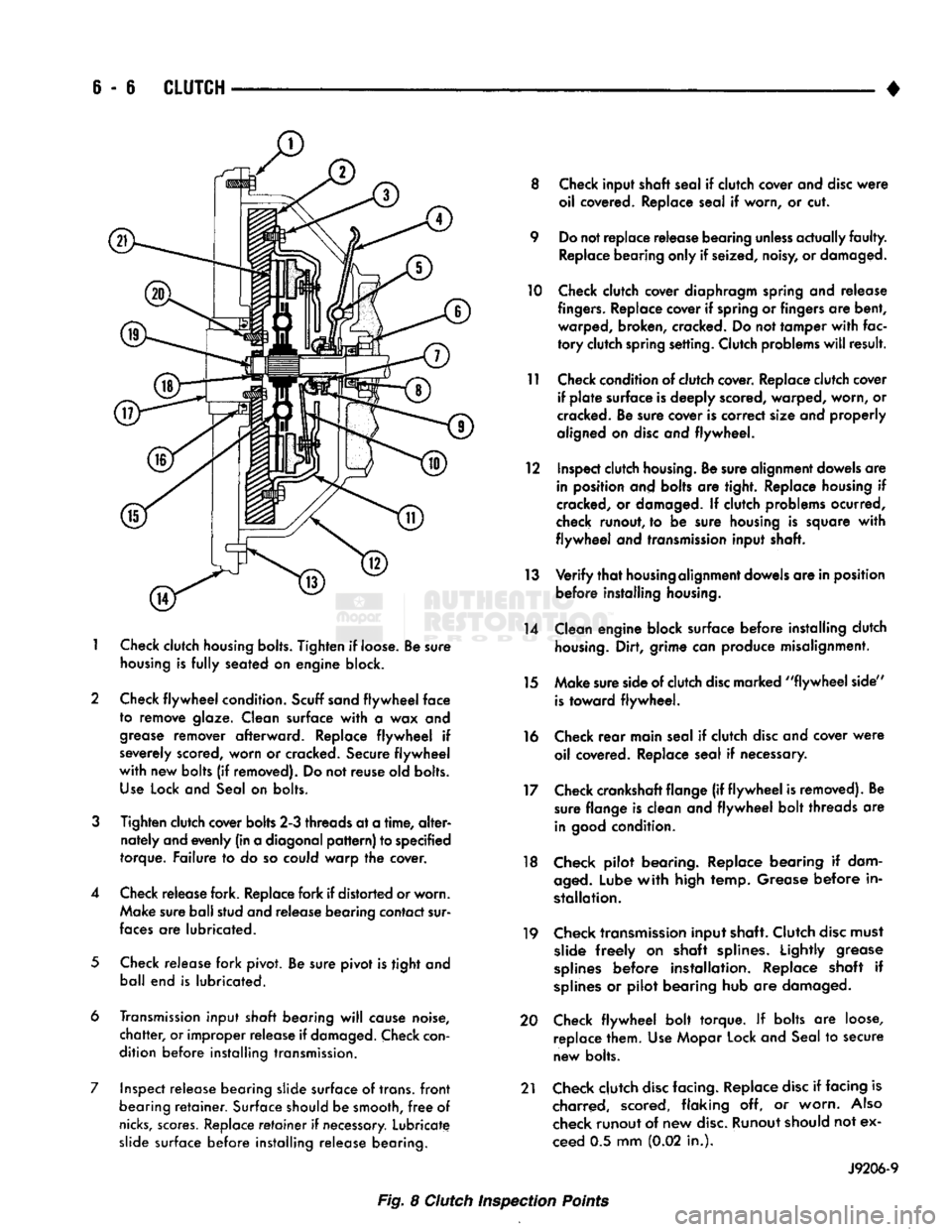
6 - 6
CLUTCH
1
Check
clutch
housing bolts.
Tighten
if loose. Be sure
housing
is
fully
seated on engine block.
2 Check
flywheel
condition.
Scuff sand
flywheel
face
to remove glaze. Clean surface
with
a wax and
grease
remover afterward. Replace
flywheel
if
severely scored, worn or cracked. Secure
flywheel
with
new bolts (if removed). Do not reuse old bolts.
Use
Lock and Seal on bolts.
3
Tighten clutch cover bolts 2-3 threads at a
time,
alter
nately and evenly (in a diagonal
pattern)
to specified
torque. Failure to do so could warp the cover.
4 Check release fork. Replace fork if distorted or worn. Make sure ball stud and release bearing contact sur
faces
are lubricated.
5
Check release fork pivot. Be sure pivot is tight and ball end is lubricated.
6 Transmission input
shaft
bearing
will
cause noise,
chatter,
or improper release if
damaged.
Check
con
dition before installing transmission.
7 Inspect release bearing slide surface of trans,
front
bearing
retainer.
Surface should be smooth,
free
of
nicks,
scores.
Replace
retainer
if
necessary.
Lubricate slide surface before installing release bearing. 8 Check input shaft seal if clutch cover and
disc
were
oil covered. Replace seal if worn, or cut.
9 Do not replace release bearing
unless
actually
faulty.
Replace bearing only if seized, noisy, or damaged.
10 Check clutch cover diaphragm spring and release
fingers.
Replace cover if spring or fingers are bent, warped, broken, cracked. Do not tamper
with
fac
tory
clutch spring setting. Clutch problems
will
result.
11 Check condition of clutch cover. Replace clutch cover if
plate
surface is deeply scored, warped, worn, or
cracked. Be sure cover is correct size and properly
aligned on
disc
and flywheel.
12 Inspect clutch
housing.
Be sure alignment dowels are in position and bolts are tight. Replace housing if
cracked, or damaged. If clutch problems ocurred,
check runout, to be sure housing is square
with
flywheel
and transmission input shaft.
13
Verify
that
housing
alignment dowels are in position before installing
housing.
14 Clean engine block surface before installing clutch
housing.
Dirt, grime can produce misalignment.
15 Make sure side of clutch
disc
marked
"flywheel
side"
is
toward flywheel.
16 Check
rear
main seal if clutch
disc
and cover
were
oil covered. Replace seal if necessary.
17 Check crankshaft flange (if
flywheel
is removed). Be sure flange is clean and
flywheel
bolt threads are
in
good
condition.
18 Check pilot bearing. Replace bearing if dam
aged.
Lube
with
high temp. Grease before in
stallation.
19 Check transmission input shaft. Clutch
disc
must slide
freely
on shaft splines. Lightly grease
splines
before installation. Replace shaft if
splines
or pilot bearing hub are damaged.
20 Check
flywheel
bolt torque. If bolts are loose, replace them. Use Mopar Lock and Seal to secure
new bolts.
21 Check clutch
disc
facing. Replace
disc
if facing is charred, scored, flaking off, or worn.
Also
check runout of new
disc.
Runout should not ex
ceed 0.5 mm (0.02 in.).
J9206-9
Fig. 8 Clutch Inspection Points
Page 264 of 1502
•
CLUTCH
S - 11
CLUTCH
SERVICE
INDEX
page
Clutch
Cover
and
Disc
Installation—All
11
Clutch
Cover
and
Disc
Removal—All
. 11
Clutch
Housing
Installation
13
Clutch
Housing
Removal
12
Clutch
Linkage
Service
14
CLUTCH
COVER
AND
DISC
REMOVAL—ALL
(1) Raise vehicle.
(2) Remove transmission and remove transfer case
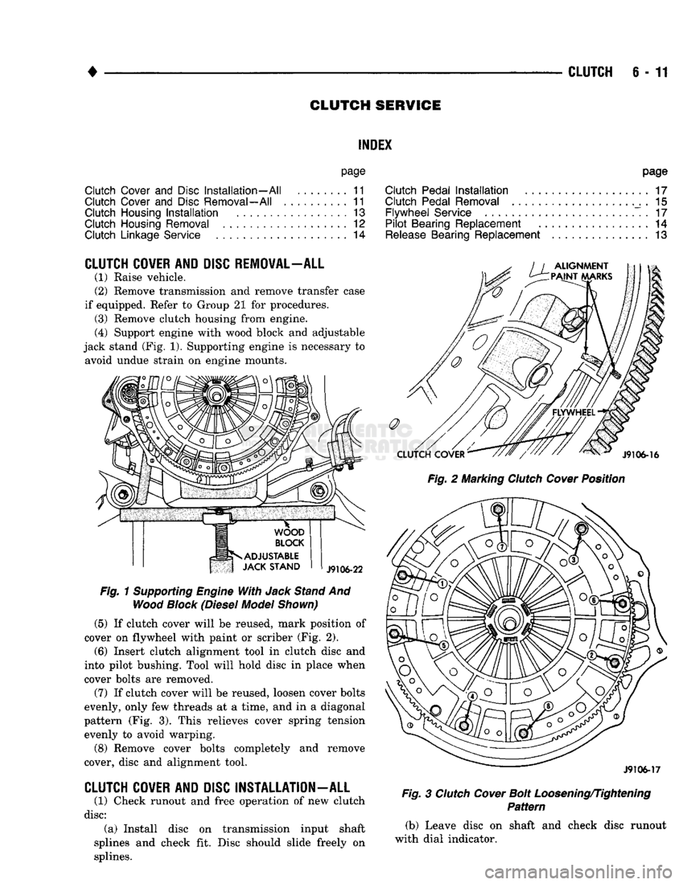
if equipped. Refer to Group 21 for procedures. (3) Remove clutch housing from engine.
(4) Support engine with wood block and adjustable
jack stand (Fig. 1). Supporting engine is necessary to avoid undue strain on engine mounts.
Fig.
1
Supporting
Engine
With
Jack
Stand
And
Wood
Block
(Diesel
Model
Shown)
(5)
If clutch cover will be reused, mark position of
cover on flywheel with paint or scriber (Fig. 2).
(6)
Insert clutch alignment tool in clutch disc and
into pilot bushing. Tool will hold disc in place when
cover bolts are removed.
(7) If clutch cover will be reused, loosen cover bolts
evenly, only few threads at a time, and in a diagonal
pattern (Fig. 3). This relieves cover spring tension evenly to avoid warping.
(8) Remove cover bolts completely and remove
cover, disc and alignment tool.
CLUTCH
COVER
AND
DISC
INSTALLATION
-
ALL
(1) Check runout and free operation of new clutch
disc:
(a) Install disc on transmission input shaft
splines and check fit. Disc should slide freely on
splines.
page
Clutch
Pedal
Installation
17
Clutch
Pedal
Removal
. 15
Flywheel
Service
. 17
Pilot
Bearing
Replacement
14
Release
Bearing
Replacement
13
Fig.
2 Marking
Clutch
Cover
Position
J9106-17
Fig.
3
Clutch
Cover
Bolt
Loosening/Tightening
Pattern
(b) Leave disc on shaft and check disc runout
with dial indicator.
Page 311 of 1502
ENGINE ACCESSORY DRIVE BELTS
INDEX
page
Automatic Belt Tensioner
45
Belt Diagnosis
40
Belt Removal/Installation
. 40
page
Belt Schematics
40
Belt Tension
40
General
Information
40
GENERAL
INFORMATION
All vehicles are available with either
a
3.9L (V-6),
a 5.2L (V-8),
a
5.9L (gas V-8) or
a
5.9L (in-line 6 cyl
inder diesel) engine. The accessory drive components
are
operated
by a
single, crankshaft driven, serpentine drive belt on all
engines. An automatic belt tensioner
is
used to main
tain correct belt tension
at all
times. Refer
to
Auto matic Belt Tensioner proceeding
in
this group.
BELT DIAGNOSIS SERPENTINE DRIVE BELT DIAGNOSIS-ALL
ENGINES
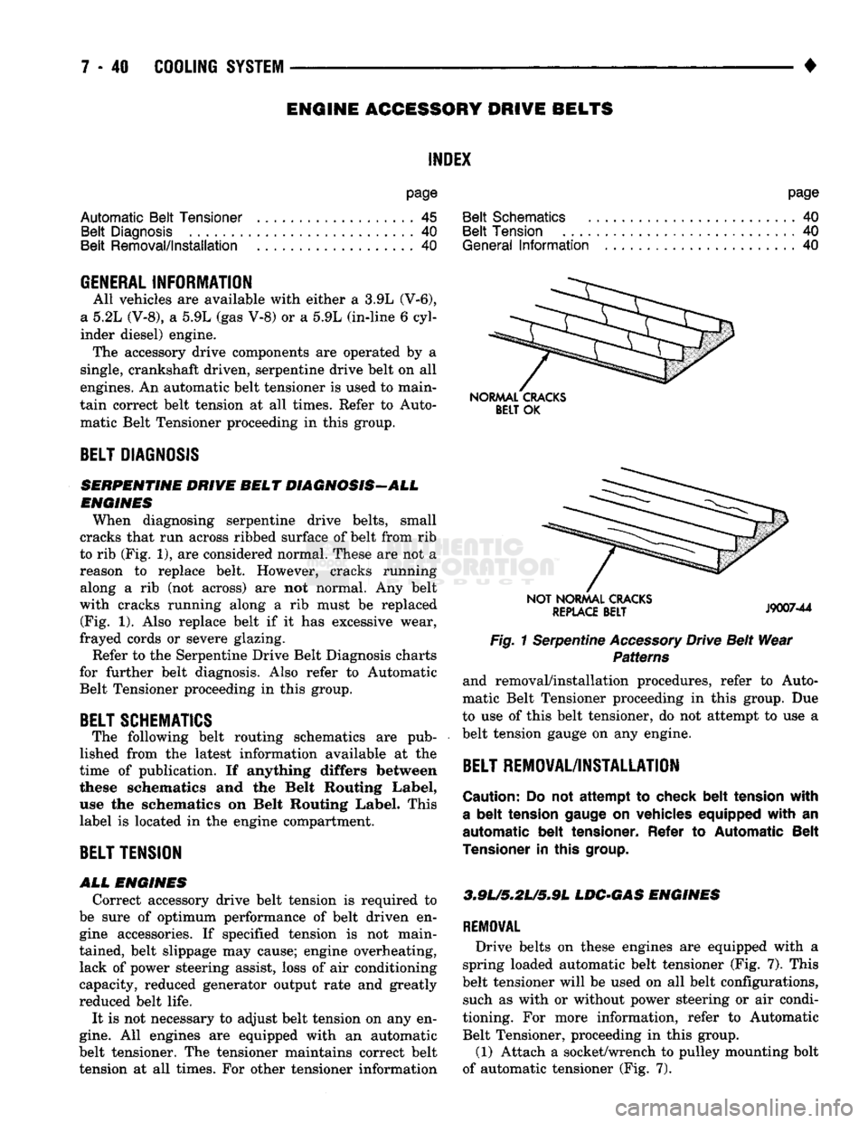
When diagnosing serpentine drive belts, small
cracks that run across ribbed surface of belt from rib
to rib (Fig. 1), are considered normal. These are not
a
reason
to
replace belt. However, cracks running along
a rib (not
across)
are not
normal.
Any
belt
with cracks running along
a rib
must
be
replaced (Fig.
1).
Also replace belt
if it has
excessive wear,
frayed cords
or
severe glazing.
Refer to the Serpentine Drive Belt Diagnosis charts
for further belt diagnosis. Also refer
to
Automatic Belt Tensioner proceeding
in
this group.
BELT SCHEMATICS
The following belt routing schematics
are
pub
lished from
the
latest information available
at the
time
of
publication.
If
anything differs between
these schematics
and the
Belt Routing Label,
use
the
schematics
on
Belt Routing Label. This
label
is
located
in
the engine compartment.
BELT TENSION
ALL
ENGINES
Correct accessory drive belt tension
is
required
to
be sure
of
optimum performance
of
belt driven
en
gine accessories.
If
specified tension
is not
main
tained, belt slippage may cause; engine overheating, lack
of
power steering assist, loss
of
air conditioning
capacity, reduced generator output rate and greatly
reduced belt life.
It
is
not necessary
to
adjust belt tension on any en
gine.
All
engines
are
equipped with
an
automatic
belt tensioner. The tensioner maintains correct belt tension
at all
times. For other tensioner information
NORMAL CRACKS
BELT
OK
NOT NORMAL CRACKS
REPLACE
BELT
J9007-44
Fig. 1 Serpentine Accessory Drive Belt Wear Patterns
and removal/installation procedures, refer
to
Auto
matic Belt Tensioner proceeding
in
this group.
Due
to use
of
this belt tensioner, do not attempt
to
use
a
belt tension gauge
on
any engine.
BELT REMOVAL/INSTALLATION
Caution:
Do not
attempt
to
check belt tension with
a
belt
tension gauge
on
vehicles equipped with
an
automatic belt tensioner. Refer
to
Automatic Belt
Tensioner
in
this
group.
3.9L/5,2U5*9L
LDC-GAS ENGINES
REMOVAL
Drive belts
on
these engines
are
equipped with
a
spring loaded automatic belt tensioner (Fig.
7).
This
belt tensioner will
be
used on
all
belt configurations, such
as
with
or
without power steering
or
air condi
tioning.
For
more information, refer
to
Automatic Belt Tensioner, proceeding
in
this group.
(1) Attach
a
socket/wrench
to
pulley mounting bolt
of automatic tensioner (Fig.
7).
Page 432 of 1502
•
WINDSHIELD WIPER
AND
WASHER SYSTEMS
8K - 1
WINDSHIELD WIPER
AND
WASHER SYSTEMS
CONTENTS
page
INTERMITTENT WINDSHIELD WIPER FUNCTION AND SWITCH TESTING PROCEDURES
6
TWO SPEED WINDSHIELD WIPER MOTOR
AND
SWITCH TESTING PROCEDURES
1
GENERAL
INFORMATION
The windshield wipers
can be
operated with
the
windshield wiper switch only when
the
ignition switch
is in the
ACCESSORY
or RUN
position.
A
fuse located
in the
fuse block protects
the
circuitry
of
the wiper system
and the
vehicle. The same motor
is
used
for
standard
and
intermit
tent wipe systems. The wiper motor
has
permanent magnet fields.
The
speeds
are
determined
by
current flow
to the
appro
priate
set of
brushes. The intermittent wipe system
in
addition
to low
page
WINDSHIELD WASHERS .. 10
WINDSHIELD WIPER SYSTEM SERVICE PROCEDURES 7
and high speed,
has a
delay mode.
The
delay mode
has
a
range
of 2 to 15
seconds. This
is
accomplished
by
a
variable resistor
in the
wiper switch
and is
con trolled electrically
by a
control module.
The wiper system completes
the
wipe cycle when
the switch
is
turned
OFF. The
blades park
in the
lowest portion
of the
wipe pattern.
Depressing
the
washer knob while
the
system
is in
the
OFF
position, • turns
the
wiper motor
on
• allows
the
motor
to
operate through
3-4
wipe
cy
cles
and
then turn
OFF.
TWO SPEED WINDSHIELD WIPER MOTOR
AND
SWITCH TESTING PROCEDURES INDEX
page
Multifunction
(Two
Speed
Wiper) Switch Testing
Procedures
4
TWO SPEED WIPER MOTOR TESTING PROCEDURES
The following
is a
list
of
general wiper motor sys
tem problems.
It
contains
the
tests that
are to be
per
formed
to
locate
the
faulty part,
and the
corrective action
to be
taken.
The
same motor
is
used
for
stan
dard
and
optional systems.
If the
malfunction
in
volves only
the
Delay mode, switch,
or
wiring, refer
to
the
Intermittent Windshield Wiper Motor
and
Switch Service Procedures.
CONDITION
Motor will
not run in any
switch position.
PROCEDURE
(1) Check
for a
blown fuse
in the
fuse block.
(a)
If
fuse
is
good, proceed
to
step
No. 2.
(b)
If
fuse
is
defective, replace
and
check motor
operation
in all
switch positions.
(c)
If
motor
is
still inoperative
and the
fuse does
not blow, proceed
to
step
No. 2.
page
Two Speed
Wiper Motor Testing Procedures
1
(d)
If
replacement fuse blows, proceed
to
step
No.
5.
(2) Place switch
in low
speed position.
(3) Listen
to
motor.
If you
cannot hear
it
running,
proceed
to
step
No. 4. If you
hear
it
running, check
motor output shaft.
If
output shaft
is not
turning,
re
place motor assembly.
If it is
turning, crank
arm or
drive link
is not
properly connected. Replace worn
parts and/or properly connect drive link
to the
motor output shaft.
(4) Connect
a
voltmeter between motor terminal
"L"
and
ground strap
(Fig. 1). If
there
is no
voltage
or very little voltage (less than
one
volt) present,
move negative test lead from
the
ground strap
to
bat
tery negative terminal.
(a)
If an
increase
in
voltage
is
noticed,
the
prob
lem
is a bad
ground circuit. Make sure
the
motor
mounting
is
free
of
paint
and
that nuts
or
bolts
are
tight.
Page 608 of 1502
•
ENGINES
9 - 3
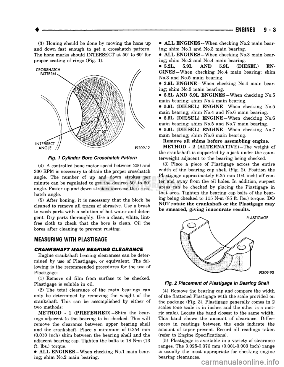
(3) Honing
should be
done
by moving the
hone
up
and down
fast
enough
to get a Crosshatch pattern.
The hone
marks should
INTERSECT
at 50° to 60° for
proper seating
of
rings (Fig.
1).
Fig.
1
Cylinder
Bore
Crosshatch
Pattern
(4)
A
controlled hone motor speed between
200 and
300
RPM is
necessary
to
obtain
the
proper Crosshatch angle.
The
number
of up and
down strokes
per
minute
can be
regulated
to get the
desired
50° to 60°
angle. Faster
up and
down strokes increase
the
cross-
hatch angle.
(5) After honing,
it is
necessary that
the
block
be
cleaned
to
remove
all
traces
of
abrasive.
Use a
brush
to wash parts with
a
solution
of hot
water
and
deter gent.
Dry
parts thoroughly.
Use a
clean, white, lint-
free cloth
to
check that
the
bore
is
clean.
Oil the
bores after cleaning
to
prevent rusting.
MEASURING
WITH
PLASTIGAGE
CRANKSHAFT
MAIN BEARING CLEARANCE Engine crankshaft bearing clearances
can be
deter
mined
by use of
Plastigage,
or
equivalent.
The
fol lowing
is the
recommended procedures
for the use of
Plastigage:
(1) Remove
oil
film from surface
to be
checked.
Plastigage
is
soluble
in oil.
(2)
The
total clearance
of the
main bearings
can
only
be
determined
by
removing
the
weight
of the
crankshaft. This
can be
accomplished
by
either
of
two methods:
METHOD - 1
(PREFERRED)—Shim
the
bear
ings adjacent
to the
bearing
to be
checked. This will
remove
the
clearance between upper bearing shell and
the
crankshaft. Place
a
minimum
of
0.254
mm
(0.010 inch) shim between
the
bearing shell
and the
adjacent bearing cap. Tighten
the
bolts
to 18 N*m (13
ft.
lbs.)
torque. •
ALL
ENGINES—When checking
No.l
main bear
ing; shim
No.2
main bearing. •
ALL
ENGINES-When checking
No.2
main bear
ing; shim
No.l and No.3
main bearing.
•
ALL
ENGINES-When checking No.3 main bear
ing; shim
No.2 and No.4
main bearing.
•
5.2L, 5.9L AND 5.9L
(DIESEL)
EN
GINES—When checking
No.4
main bearing; shim
No.3
and No.5
main bearing.
•
3.9L
ENGINE—When checking
No.4
main bear
ing; shim
No.3
main bearing.
•
5.2L AND 5.9L
ENGINES—When checking
No.5
main bearing; shim
No.4
main bearing.
•
5.9L
(DIESEL) ENGINE-When checking
No.5
main bearing; shim
No.4 and No.6
main bearing.
•
5.9L
(DIESEL) ENGINE-When checking
No.6
main bearing; shim
No.5 and No.7
main bearing.
•
5.9L
(DIESEL) ENGINE-When checking
No.7
main bearing; shim
No.6
main bearing.
Remove
all
shims before assembling engine.
METHOD
- 2
(ALTERNATIVE)—The weight
of
the crankshaft
is
supported
by a
jack under
the
coun
terweight adjacent
to the
bearing being checked.
(3) Place
a
piece
of
Plastigage across
the
entire
width
of the
bearing
cap
shell
(Fig. 2).
Position
the
Plastigage approximately
6.35 mm (1/4
inch)
off
cen
ter
and
away from
the oil
holes.
In
addition, suspect areas
can be
checked
by
placing
the
Plastigage
in
that area. Tighten
the
bearing
cap
bolts
of the
bear
ing being checked
to 115 N»m (85 ft. lbs.)
torque.
DO
NOT rotate
the
crankshaft
or the
Plastigage
may
be smeared, giving inaccurate results.
Fig.
2
Placement
of
Plastigage
in
Bearing
Shell
(4) Remove
the
bearing
cap and
compare
the
width
of
the
flattened Plastigage with
the
scale provided
on
the package
(Fig. 3).
Plastigage generally comes
in 2
scales
(one
scale
is in
inches
and the
other
is a
met
ric scale). Locate
the
band closest
to the
same width.
This band shows
the
amount
of
clearance. Differ ences
in
readings between
the
ends indicate
the
amount
of
taper present. Record
all
readings taken (refer
to
Engine Specifications).
(5) Plastigage
is
available
in a
variety
of
clearance
ranges.
The
0.025-0.076
mm
(0.001-0.003 inch) range is usually
the
most appropriate
for
checking engine
bearing clearances.
Page 1002 of 1502
•
TRANSMISSION
AND
TRANSFER
CASE
21 - 1
CONTENTS
page
AUTOMATIC
TRANSMISSI0N-32RH/36RH/
37RH/42RH/46RH
73
G360
MANUAL
TRANSMISSION
46
6360
TRANSMISSION
OVERHAUL
..........
53
NP2Q5
TRANSFER
CASE
................
342
page
NP241
TRANSFER
CASE
350
NV4500 MANUAL
TRANSMISSION
1
NV4500
TRANSMISSION
OVERHAUL
.........
6
TRANSMISSION/TRANSFER
CASE
SPECIFICATIONS
.....................
364
NV4300
MANUAL TRANSMISSION
INDEX
page
Gear Ratios
1
General
Information
1
Recommended
Lubricant—Capacity—Fill
Level
... 1
Shift
Pattern
1
Transmission Diagnosis
2
page
Transmission
Identification
1
Transmission
Installation—2-Wheel
Drive
4
Transmission
Installation—4-Wheel
Drive
........
5
Transmission
Removal—2-Wheel
Drive
3
Transmission
Removal—4-Wheel
Drive
4
GENERAL
INFORMATION The NV4500
is a
five-speed, constant mesh manual
transmission (Fig.
1). All
gear ranges including
re
verse
are
synchronized. Fifth gear
is an
overdrive
range with
a
ratio
of
0.74:1.
The transmission has
a
cast iron gear case and aluminum shift cover. The NV4500
is a
top loader style transmission. The
shift lever
is
located
in the
shift cover and operates
the shift forks and rails directly. The shift forks and
rails
are all
located within
the
aluminum cover
which
is
bolted
to
the top
of
the gear case.
A reverse gear inhibitor mechanism prevents
re
verse gear engagement when shifting into forward
gear ranges. The inhibitor mechanism
is
located
in
the shift cover.
Tapered roller bearings support
the
drive gear,
mainshaft
and
countershaft
in the
gear case. Pilot
roller bearings
in
the drive gear hub support the for
ward end
of
the mainshaft. The mainshaft gears
are
all supported
on
caged type roller bearings. Drive
gear thrust reaction
is
controlled
by a
needle type
thrust bearing. The bearing
is
located
at
the forward
end
of
the mainshaft.
TRANSMISSION
IDENTIFICATION The NV4500 transmission identification
tag is at
tached
to
the driver side PTO cover (Fig.
2).
The
tag
provides
the
transmission model number,
build date and part number.
Be
sure
to
reinstall
the
I.D.
tag if
removed during service. The information
on the tag
is
essential
to
correct parts ordering.
RECOMMENDED
LUBRICANT-CAPACITY-FILL
LEVEL
Recommended lubricant
for
the NV4500
is
Castrol
Syntorq. This
is a
SAE 75W-90 synthetic gear lubri
cant with
an
API grade rating
of
GL
4.
Syntorq
is
the only lubricant recommended
for
use
in
NV4500 transmissions. Dry fill lubricant capacity
is
approximately 3.78
li
ters
(8
pints). Correct lubricant fill level
is to
the bottom edge
of
the fill plug hole (Fig. 3). Check fill level only when
the transmission
is
level.
GEAR
RATIOS
NV4500 gear ratios are:
First gear:
5.61:1
Second gear: 3.04:1
Third gear:
1.67:1
Fourth gear:
1.00:1
Fifth gear: 0.74:1
Reverse gear:
5.61:1
SHIFT
PATTERN
The NV4500 shift pattern
is in a
modified
H
pat
tern (Fig. 4). Overdrive fifth and reverse gears are
in
line and outboard of the first through fourth gear po
sitions.
TRANSMISSION
AND
TRANSFER
CASE
Page 1152 of 1502
•
AUTOMATIC
TRANSMISSION
REMOVAL
AND
INSTALLATION
21 - 151
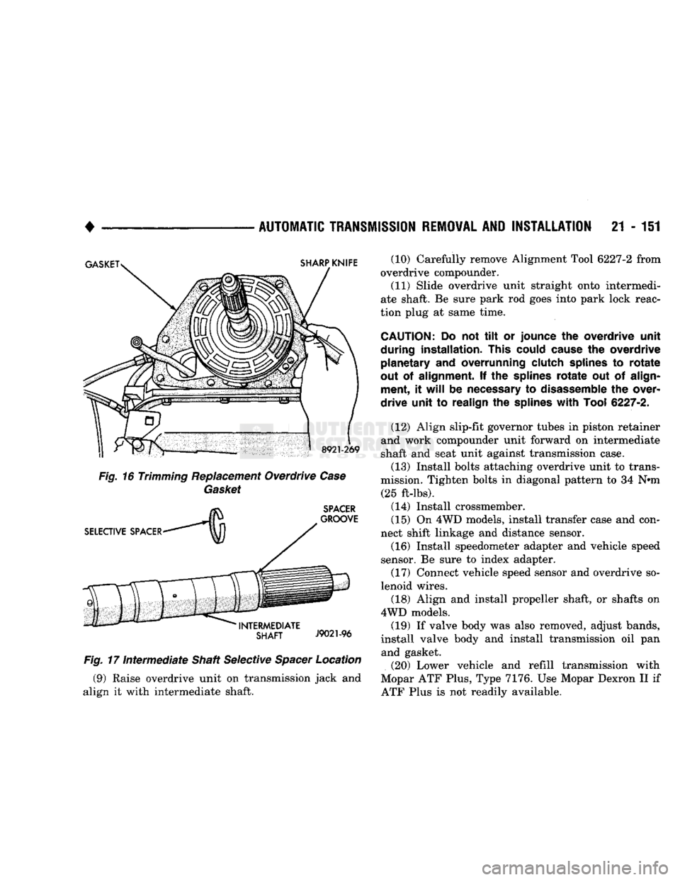
Fig.
17
Intermediate
Shaft Selective
Spacer
Location (9) Raise overdrive unit on transmission jack and
align it with intermediate shaft. (10) Carefully remove Alignment Tool 6227-2 from
overdrive compounder.
(11) Slide overdrive unit straight onto intermedi
ate shaft. Be sure park rod goes into park lock reac
tion plug at same time.
CAUTION:
Do not tilt or
jounce
the
overdrive unit
during installation. This could cause
the
overdrive planetary
and
overrunning clutch splines
to
rotate
out
of
alignment.
If the
splines
rotate
out of
align ment,
it
will
be
necessary
to
disassemble
the
over
drive unit
to
realign
the
splines
with
Tool
6227-2.
(12) Align slip-fit governor tubes in piston retainer
and work compounder unit forward on intermediate
shaft and seat unit against transmission case.
(13) Install bolts attaching overdrive unit to trans
mission. Tighten bolts in diagonal pattern to 34 N»m (25 ft-lbs).
(14) Install crossmember.
(15) On 4WD models, install transfer case and con
nect shift linkage and distance sensor. (16) Install speedometer adapter and vehicle speed
sensor. Be sure to index adapter.
(17) Connect vehicle speed sensor and overdrive so
lenoid wires.
(18) Align and install propeller shaft, or shafts on
4WD models. (19) If valve body was also removed, adjust bands,
install valve body and install transmission oil pan and gasket.
(20) Lower vehicle and refill transmission with
Mopar ATF Plus, Type 7176. Use Mopar Dexron II if
ATF Plus is not readily available.
Page 1191 of 1502
21
- 190
TRANSMISSION OVERHAUL—32RH
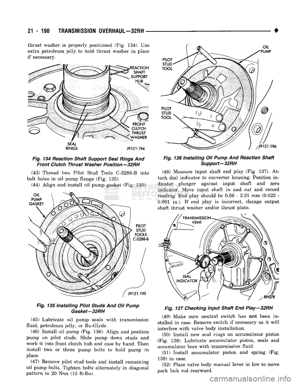
• thrust washer is properly positioned (Fig. 134). Use
extra petroleum jelly to hold thrust washer in place
if necessary.
SEAL
RINGS
J9121-194
Fig.
134 Reaction Shaft
Support
Seal
Rings
And Front
Clutch
Thrust
Washer
Position—32RH (43) Thread two Pilot Stud Tools C-32S8-B into
bolt holes in oil pump flange (Fig. 135).
(44) Align and install oil pump gasket (Fig. 135).
Fig.
135 Installing Pilot
Studs
And Oil
Pump
Gasket-32RH
(45) Lubricate oil pump seals with transmission
fluid, petroleum jelly, or Ru-Glyde.
(46) Install oil pump (Fig. 136). Align and position
pump on pilot studs. Slide pump down studs and
work it into front clutch hub and case by hand. Then install two or three pump bolts to hold pump in
place.
(47) Remove pilot stud tools and install remaining
oil pump bolts. Tighten bolts alternately in diagonal
pattern to 20 N-m (15 ft-lbs).
Fig.
136 Installing Oil
Pump
And Reaction Shaft
Support-32RH
(48) Measure input shaft end play (Fig. 137). At
tach dial indicator to converter housing. Position in dicator plunger against input shaft and zero
indicator. Move input shaft in and out and record
reading. End play should be 0.56 - 2.31 mm (0.022 - 0.091 in.). If end play is incorrect, change output
shaft thrust washer and/or thrust plate.
Fig.
137
Checking
Input Shaft End Play-32RH
(49) Make sure neutral switch has not been in
stalled in case. Remove switch if necessary as it will
interfere with valve body installation.
(50) Install new seal rings on accumulator piston
(Fig. 138). Lubricate accumulator piston, seals and
accumulator bore with transmission fluid. (51) Install accumulator piston and spring (Fig.
138) in case.
(52) Place valve body manual lever in low to move
park lock rod rearward.