1993 DODGE TRUCK battery replacement
[x] Cancel search: battery replacementPage 1387 of 1502

23
- 4
BODY
COMPONENTS
• INSTALLATION
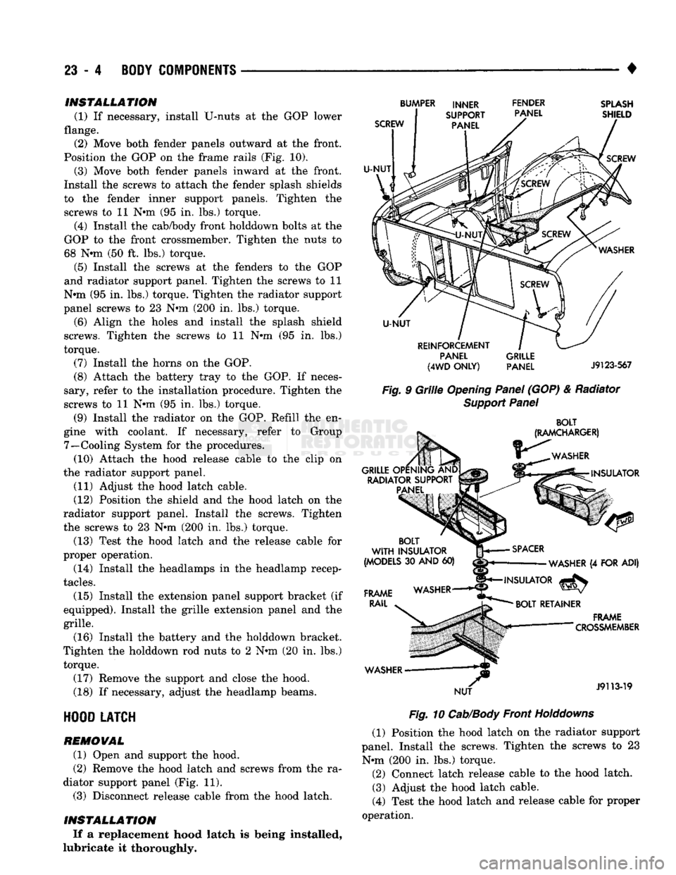
(1) If necessary, install U-nuts at the GOP lower
flange. (2) Move both fender panels outward at the front.
Position the GOP on the frame rails (Fig. 10).
(3) Move both fender panels inward at the front.
Install the screws to attach the fender splash shields
to the fender inner support panels. Tighten the
screws to 11 N#m (95 in. lbs.) torque.
(4) Install the cab/body front holddown bolts at the
GOP to the front crossmember. Tighten the nuts to
68 Nnn (50 ft. lbs.) torque.
(5) Install the screws at the fenders to the GOP
and radiator support panel. Tighten the screws to 11
N»m (95 in. lbs.) torque. Tighten the radiator support
panel screws to 23 Nnn (200 in. lbs.) torque.
(6) Align the holes and install the splash shield
screws. Tighten the screws to 11 N»m (95 in. lbs.)
torque.
(7) Install the horns on the GOP.
(8) Attach the battery tray to the GOP. If neces
sary, refer to the installation procedure. Tighten the
screws to 11 Nnn (95 in. lbs.) torque.
(9) Install the radiator on the GOP. Refill the en
gine with coolant. If necessary, refer to Group 7—Cooling System for the procedures. (10) Attach the hood release cable to the clip on
the radiator support panel.
(11) Adjust the hood latch cable.
(12) Position the shield and the hood latch on the
radiator support panel. Install the screws. Tighten
the screws to 23 Nnn (200 in. lbs.) torque.
(13) Test the hood latch and the release cable for
proper operation.
(14) Install the headlamps in the headlamp recep
tacles.
(15) Install the extension panel support bracket (if
equipped). Install the grille extension panel and the
grille.
(16) Install the battery and the holddown bracket.
Tighten the holddown rod nuts to 2 Nnn (20 in. lbs.) torque.
(17) Remove the support and close the hood.
(18) If necessary, adjust the headlamp beams.
HOOD
LATCH
REMOVAL
(1) Open and support the hood.
(2) Remove the hood latch and screws from the ra
diator support panel (Fig. 11). (3) Disconnect release cable from the hood latch.
INSTALLATION If a replacement hood latch is being installed,
lubricate it thoroughly.
SCREW
U-NUT
BUMPER INNER FENDER
SUPPORT PANEL
PANEL
SPLASH
SHIELD
SCREW
U-NUT
REINFORCEMENT PANEL
(4WD
ONLY)
GRILLE
PANEL
J9123-567
Fig.
9
Grille
Opening
Panel
(GOP) & Radiator
Support
Panel
BOLT
(RAMCHARGER)
WASHER
GRILLE OPENING AND RADIATOR SUPPORT PANEL INSULATOR
BOLT
WITH
INSULATOR
(MODELS
30
AND
60)
FRAME
RAIL
WASHER NUT
SPACER
WASHER
(4
FOR ADI)
INSULATOR
^
BOLT
RETAINER
.
FRAME
— "
"
CROSSMEMBER
J9113-19
Fig.
10
Cab/Body
Front
Holddowns
(1) Position the hood latch on the radiator support
panel. Install the screws. Tighten the screws to 23 Nnn (200 in. lbs.) torque. (2) Connect latch release cable to the hood latch. (3) Adjust the hood latch cable.
(4) Test the hood latch and release cable for proper
operation.
Page 1392 of 1502

•
BODY
COMPONENTS
23 - 9 (8) Remove the fender and the inner panel from
the cab/body.
(9) Remove the screws that attach the fender inner
panel to the fender panel. Remove the inner panel from the fender outer panel (Fig. 23).
INSTALLATION (1) Position the fender inner panel liner on the
outer panel. Install the screws. Tighten them to 23
N-m (200 in. lbs.) torque.
(2) Position the fender with inner panel on the cab/
body.
(3) Install the screws that attach the fender to the
radiator support panel. Tighten the screws to 23 N-m (200 in. lbs.) torque.
(4) Install the screws that attaches the fender and
inner panel to the dash panel. Tighten the screws to
23 N-m (200 in. lbs.) torque.
(5)
Install the screw and nut that attaches the top
of the fender to the cowl. Tighten the screw and nut
to 23 N-m (200 in. lbs.) torque. (6) If removed, install the battery and tray.
Tighten the battery tray bolts to 11 N-m (95 in. lbs.)
torque. Tighten the support bracket-to-fender inner panel bolt to 23 N-m (200 in. lbs.) torque.
(7) Install the grille extension panel and the grille.
(8) Remove the support and close the hood.
FENDER
PANEL
GRILLE
EXTENSION PANEL
J9123-565
Fig.
23 Front Fender Outer Panel
SPLASH
SHIELDS—FRONT
FENDER
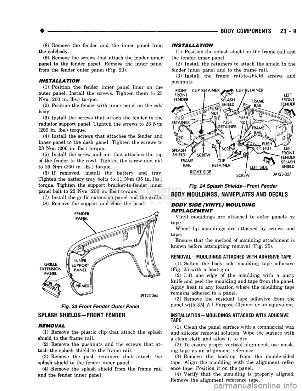
REMOVAL (1) Remove the plastic clip that attach the splash
shield to the frame rail. (2) Remove the pushnuts and the screws that at
tach the splash shield to the frame rail. (3) Remove the push retainers that attach the
splash shield to the fender inner panel. (4) Remove the splash shield from the frame rail
and the fender inner panel. INSTALLATION
(1) Position the splash shield on the frame rail and
the fender inner panel.
(2) Install the retainers to attach the shield to the
fender inner panel and to the frame rail. (3) Install the frame rail-to-shield screws and
pushnuts.
RIGHT
FRONT
FENDER CLIP RETAINER
CLIP RETAINER
FRAME LEFT
FRONT
FENDER
SPLASH
SHIELD
FRAME RAIL
RIGHT SIDE
SCREW
LEFT
FRONT
FENDER
SPLASH
SHIELD
J9123-327
Fig.
24
Splash
Shields—Front
Fender
BODY
MOULDINGS, NAMEPLATES AND
DECALS
BODY SIDE (VINYL) MOULDING
REPLACEMENT
Vinyl mouldings are attached to outer panels by
tape.
Wheel lip mouldings are attached by screws and
tape.
Ensure that the method of moulding attachment is
known before attempting removal (Fig. 25).
REMOVAL—MOULDINGS
ATTACHED WITH ADHESIVE TAPE
(1) Soften the body side moulding tape adhesive
(Fig. 25 with a heat gun. (2) Lift one edge of the moulding with a putty
knife and peel the moulding and tape from the panel.
Apply heat to any location where the moulding tape remains adhered to a panel.
(3) Remove the residual tape adhesive from the
panel with 3M All Purpose Cleaner or an equivalent.
INSTALLATION
—
MOULDINGS
ATTACHED WITH ADHESIVE
TAPE
(1) Clean the panel surface with a commercial wax
and silicone removal solution. Wipe the surface with
a clean cloth and allow it to dry.
(2) To ensure proper vertical alignment, use mask
ing tape as an alignment reference.
(3) Remove the backing from the double-sided
tape.
Align the moulding with the alignment refer
ence tape. Position it on the panel.
(4) Verify that the moulding is properly aligned.
Remove the alignment reference tape.
Page 1458 of 1502

•
HEATING
AND AIR
CONDITIONING
24 - 21 (a) Loosen both test hoses at the manifold gauge
set. Tighten the hoses as soon as the air is purged. (b) Loosen charging hose connection at manifold
gauge set. This will purge air from the charging
hose.
Tighten connection as soon as air is purged.
(9) With vehicle windows open and hood up, oper
ate engine at 1,300 RPM. (10) Place air conditioner control on A/C and place
the fan switch on high. (11) If necessary, block the condenser to maintain
a discharge pressure of 1 550-1 725 kPag (225-250
psig).
System must be charged through the evapora
tor suction service ports as follows:
(a) Slowly open the suction service gauge valve.
Meter flow of refrigerant by adjusting the suction service gauge valve so the pressure registered at
the suction service gauge does not exceed 345 kPag
COMPRESSOR
J
(50
psig). Keep refrigerant container upright.
(b) Add refrigerant gas until there is no foam visi
ble at the sight glass. As soon as all foam clears, note the weight registered on the refrigerant scale.
(c) Watch the refrigerant weighing scale and add
437 g (14 oz.) of refrigerant (equivalent to 1 can).
(d) Close the suction gauge valve.
CAUTION:
TOO
much
refrigerant
in the
system
can
cause
abnormally high discharge pressures. Care
must
be
used
so the
exact recommended amount
of
refrigerant
is
added
after
foam clears
in the
sight
glass.
(e) Close dispensing manifold valve. Remove test
hoses and adapters from the service ports of com
pressor and install protective caps at service ports.
RVICE (SD-709)
INDEX
page
Compressor
21
Compressor
Shaft Seal
.................... 25
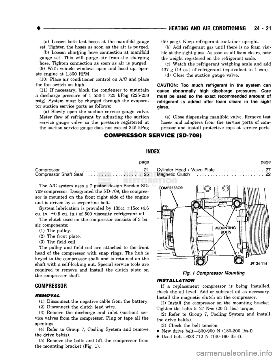
The A/C system uses a 7 piston design Sanden SD-
709 compressor. Designated the SD-709, the compres
sor is mounted on the front right side of the engine
and is driven by a serpentine belt.
System lubrication is provided by 135cc ±15cc (4.6
cu. in. ±0.5 cu. in.) of 500 viscosity refrigerant oil.
The clutch used on the compressor consists of 3 ba
sic components:
(1) The pulley.
(2) The front plate. (3) The field coil.
The pulley and field coil are attached to the front
head of the compressor with snap rings. The hub is keyed to the compressor shaft and is retained on the
shaft with a self-locking nut. Special service tools are
required to remove and install the clutch plate on
the compressor shaft.
COMPRESSOR
REMOVAL
(1) Disconnect the negative cable from the battery.
(2) Disconnect the clutch lead wire.
(3) Remove the discharge and inlet (suction) ser
vice valves from the compressor. Plug or tape all the
openings.
(4) Refer to Group 7, Cooling System and remove
the drive belt(s). (5) Remove the bolts and lift the compressor from
the mounting bracket (Fig. 1).
page
Cylinder Head
/
Valve Plate
27
Magnetic
Clutch
22
Fig.
1
Compressor
Mounting
INSTALLATION
If a replacement compressor is being installed,
check the oil level. Add or subtract oil as necessary.
Install the magnetic clutch on the compressor.
(1) Install the compressor on the mounting bracket.
Tighten the bolts to 27 N*m (20 ft. lbs.) torque.
(2) Refer to Group 7, Cooling System and install
the drive belt(s).
(3) Check the belt tension.
@ New drive belt-800-900 N (180-200 lbs-f).
• Used belt-623-712 N (140-160 lbs-f).