1993 DODGE TRUCK ESP
[x] Cancel search: ESPPage 662 of 1502
•
5.2L
ENGINE
9 - 57 (6) With air hose attached to an adapter installed
in No.l spark plug hole, apply 620-689 kPa (90-100
psi) air pressure.
(7) Using Valve Spring Compressor Tool
MD-998772A, compress valve spring and remove re
tainer valve locks and valve spring.
(8) Install seals on the exhaust valve stem and po
sition down against valve guides.
(9) The intake valve stem seals should be pushed
firmly and squarely over the valve guide using the valve stem as a guide. DO NOT force seal against
top of guide. When installing the valve retainer
locks,
compress the spring only enough to install the
locks.
(10) Follow the same procedure on the remaining 7
cylinders using the firing sequence 1-8-4-3-6-5-7-2.
Make sure piston in cylinder is at TDC on the valve
spring that is being removed. (11) Remove adapter from the No.l spark plug
hole.
(12) Install rocker arms.
(13) Install covers and coil wire to distributor.
(14) Install air cleaner. (15) Road test vehicle.
HYDRAULIC TAPPETS
Before disassembling any part of the engine to cor
rect tappet noise, check the oil pressure. If vehicle
has no oil pressure gauge, install a reliable gauge at the pressure sending unit. The pressure should be be
tween 207-552 kPa (30-80 psi) at 3,000 RPM. Check the oil level after the engine reaches normal
operating temperature. Allow 5 minutes to stabilize oil level, check dipstick. The oil level in the pan should never be above the
FULL mark or below the ADD OIL mark on dipstick.
Either of these 2 conditions could be responsible for
noisy tappets.
OIL LEWEL
HIGH
If oil level is above the FULL mark, it is possible
for the connecting rods to dip into the oil. With the
engine running this condition could create foam in
the oil pan. Foam in oil pan would be fed to the hy
draulic tappets by the oil pump causing them to lose
length and allow valves to seat noisily.
LOW Low oil level may allow oil pump to take in air.
When air is fed to the tappets, they lose length
which allows valves to seat noisily. Any leaks on in
take side of oil pump through which air can be drawn will create the same tappet action. Check the
lubrication system from the intake strainer to the
pump cover, including the relief valve retainer cap. When tappet noise is due to aeration, it may be in termittent or constant, and usually more than 1 tap
pet will be noisy. When oil level and leaks have been
corrected, operate the engine at fast idle. Run engine
for a sufficient time to allow all of the air inside the
tappets to be bled out.
TAPPET
NOISE DIAGNOSIS
(1) To determine source of tappet noise, operate en
gine at idle with cylinder head covers removed.
(2) Feel each valve spring or rocker arm to detect
noisy tappet. The noisy tappet will cause the affected
spring and/or rocker arm to vibrate or feel rough in
operation.
Worn valve guides or cocked springs are some
times mistaken for noisy tappets. If such is the case, noise may be dampened by applying side
thrust on the valve spring. If noise is not appre
ciably reduced, it can be assumed the noise is in
the tappet. Inspect the rocker arm push rod sockets and push rod ends for wear.
(3) Valve tappet noise ranges from light noise to a
heavy click. A light noise is usually caused by exces sive leak-down around the unit plunger or by the
plunger partially sticking in the tappet body cylin der. The tappet should be replaced. A heavy click is caused by a tappet check valve not seating or by for
eign particles becoming wedged between the plunger and the tappet body. This will cause the plunger to
stick in the down position. This heavy click will be accompanied by excessive clearance between the
valve stem and rocker arm as valve closes. In either
case,
tappet assembly should be removed for inspec
tion and cleaning.
The valve train generates a noise very much like a
light tappet noise during normal operation. Care
must be taken to ensure that tappets are making the
noise. In general, if more than one tappet seems to
be noisy, its probably not the tappets.
REMOVAL
(1) Remove the air cleaner.
(2) Remove cylinder head cover.
(3) Remove rocker assembly and push rods. Iden
tify push rods to ensure installation in original loca
tion.
(4) Remove intake manifold.
(5) Remove yoke retainer and aligning yokes.
(6) Slide Hydraulic Tappet Remover/Installer Tool
C-4129-A through opening in cylinder head and seat
tool firmly in the head of tappet.
(7) Pull tappet out of bore with a twisting motion.
If all tappets are to be removed, identify tappets to
ensure installation in original location.
(8) If the tappet or bore in cylinder block is scored,
scuffed, or shows signs of sticking, ream the bore to
next oversize. Replace with oversize tappet.
Page 665 of 1502
9
- 60 5.2L
ENGINE
(8) Turn crankshaft and camshaft to line up with
keyway location in crankshaft sprocket and in cam shaft sprocket.
(9) Lift sprockets and chain (keep sprockets tight
against the chain in position as described). (10) Slide both sprockets evenly over their respec
tive shafts and use a straightedge to check alignment
of timing marks (Fig. 5).
TIMING
MARKS
J9209-129
Fig.
5
Alignment
of Timing Marks (11) Install the camshaft bolt. Tighten the bolt to
68 Nnn (50 ft. lbs.) torque. (12) Check camshaft end play. The end play should
be 0.051-0.152 mm (0.002-0.006 inch) with a new
thrust plate and up to 0.254 mm (0.010 inch) with a used thrust plate. If not within these limits install a
new thrust plate.
CLEANING Be sure mating surfaces of chain case cover and
cylinder block are clean and free from burrs.
INSTALLATION (1) Using a new cover gasket, carefully install
chain case cover to avoid damaging oil pan gasket.
Use a small amount of Mopar Silicone Rubber Adhe sive Sealant, or equivalent, at the joint between tim
ing chain cover gasket and the oil pan gasket. Finger
tighten the timing chain cover bolts at this time.
(2) Place the smaller diameter of the oil seal over
Front Oil Seal Installation Tool 6635 (Fig. 6). Seat
the oil seal in the groove of the tool.
(3) Position the seal and tool onto the crankshaft
(Fig. 7). (4) Using the vibration damper bolt, tighten the
bolt to draw the seal into position on the crankshaft (Fig. 8).
(5) Tighten chain case cover bolts to 41 Nnn (30 ft.
lbs.) torque. Tighten oil pan bolts to 24 Nnn (215 in.
lbs.) torque.
(6) Remove the vibration damper bolt and seal in
stallation tool. (7) Install vibration damper.
(8) Install fuel lines (refer to Group 14, Fuel Sys
tem).
CRANKSHAFT
k
FRONT
OIL
SEAL
INSTALL
THIS
END
INTO
SPECIAL
TOOL
6635
J9309-44
Fig.
6
Placing
Oil
Seal
on
Installation
Tool
6635
SPECIAL
TOOL
\ | OIL
SEAL
TIMING
CHAIN
COVER
J9309-45*-
Fig.
7 Position Tool and
Seal
onto Crankshaft
(9) Install water pump and housing assembly us
ing new gaskets (refer to Group 7, Cooling System).
Tighten bolts to 41 Nnn (30 ft. lbs.) torque.
(10) Install power steering pump (refer to Group
19,
Steering).
(11) Install the serpentine belt (refer to Group 7,
Cooling System).
(12) Install the cooling system fan. Tighten the
bolts to 23 Nnn (17 ft. lbs.) torque. (13) Position the fan shroud and install the bolts.
Tighten the bolts to 11 Nnn (95 in. lbs.) torque.
(14) Fill cooling system (refer to Group 7, Cooling
System for the proper procedure).
(15) Connect the negative cable to the battery.
Page 667 of 1502
9 - 62 5.2L
ENGINE
Fig,
11 Camshaft
Bearings
Removal
and
installation
with
Tool C-3132-A
Tool C-3132-A) at back of each bearing shell. Drive out bearing shells (Fig. 11).
INSTALL A
TION-
BEARING
(1) Install new camshaft bearings with Camshaft
Bearing Remover/Installer Tool C-3132-A by sliding
the new camshaft bearing shell over proper adapter. (2) Position rear bearing in the tool. Install horse
shoe lock and by reversing removal procedure, care
fully drive bearing shell into place. (3) Install remaining bearings in the same man
ner. Bearings must be carefully aligned to bring oil
holes into full register with oil passages from the
main bearing. If the camshaft bearing shell oil holes are not in exact alignment, remove and install them
correctly. Install a new core hole plug at the rear of
camshaft. Be sure this plug does not leak.
INSTALLATION
(1) Lubricate camshaft lobes and camshaft bearing
journals and insert the camshaft to within 51 mm (2 inches) of its final position in cylinder block.
Whenever an engine has been rebuilt, a new
camshaft and/or new tappets installed, add 1
pint of Mopar Crankcase Conditioner, or equiv alent. The oil mixture should be left in engine
for a minimum of 805 km (500 miles). Drain at
the next normal oil change.
(2) Install Camshaft Gear Installer Tool C-3509
with tongue back of distributor drive gear (Fig. 12).
Fig.
12 Camshaft
Holding
Tool C-3509 (Installed
Position)
• — —— — — •
Fig.
13
Alignment
of Timing Marks
(10) Install the camshaft bolt/cup washer. Tighten
bolt to 68 N«m (50 ft. lbs.) torque. (11) Measure camshaft end play. Refer to Specifi
cations for proper clearance. If not within limits in stall a new thrust plate.
(12) Each tappet reused must be installed in the
same position from which it was removed. When
camshaft is replaced, all of the tappets must be
replaced.
DISTRIBUTOR
REMOVAL
Refer to Group 8D, Ignition Systems for the proper
procedure.
REMOVAL-DRIVE SHAFT BUSHING
(1) Insert Distributor Drive Shaft Bushing Puller
Tool C-3052 into old bushing and thread down until a tight fit is obtained (Fig. 14). (3) Hold tool in position with a distributor lock-
plate bolt. This tool will restrict camshaft from being
pushed in too far and prevent knocking out the welch
plug in rear of cylinder block Tool should remain installed until the camshaft and crankshaft sprockets and timing chain have been installed.
(4)
Install camshaft thrust plate and chain oil tab.
Make sure tang enters lower right hole in thrust plate. Tighten bolts to 24 N*m (210 in. lbs.) torque.
Top edge of tab should be flat against thrust plate in
order to catch oil for chain lubrication.
(5) Place both camshaft sprocket and crankshaft
sprocket on the bench with timing marks on exact
imaginary center line through both camshaft and crankshaft bores.
(6) Place timing chain around both sprockets. (7) Turn crankshaft and camshaft to line up with
keyway location in crankshaft sprocket and in camshaft sprocket.
(8) Lift sprockets and chain (keep sprockets tight
against the chain in position as described). (9) Slide both sprockets evenly over their respec
tive shafts and use a straightedge to check alignment of timing marks (Fig. 13).
Page 692 of 1502
•
5.9L ENGINE
9 - 87 (6) With air hose attached to an adapter installed
in No.l spark plug hole, apply 620-689 kPa (90-100
psi) air pressure.
(7) Using Valve Spring Compressor Tool
MD-998772A, compress valve spring and remove re
tainer valve locks and valve spring.
(8) Install seals on the exhaust valve stem and po
sition down against valve guides.
(9) The intake valve stem seals should be pushed
firmly and squarely over the valve guide using the
valve stem as a guide. DO NOT force seal against
top of guide. When installing the valve retainer
locks,
compress the spring only enough to install the
locks.
(10) Follow the same procedure on the remaining 7
cylinders using the firing sequence 1-8-4-3-6-5-7-2.
Make sure piston in cylinder is at TDC on the valve spring that is being removed. (11) Remove adapter from the No.l spark plug
hole.
(12) Install rocker arms.
(13) Install covers and coil wire to distributor.
(14) Install air cleaner.
(15) Road test vehicle.
HYDRAULIC
TAPPETS
Before disassembling any part of the engine to cor
rect tappet noise, check the oil pressure. If vehicle
has no oil pressure gauge, Install a reliable gauge at
the pressure sending unit. The pressure should be be
tween 207-552 kPa (30-80 psi) at 3,000 RPM. Check the oil level after the engine reaches normal
operating temperature. Allow 5 minutes to stabilize
oil level, check dipstick. The oil level in the pan should never be above the
FULL mark or below the ADD OIL mark on dipstick.
Either of these 2 conditions could be responsible for
noisy tappets.
OIL LEVEL
HIGH
If oil level Is above the FULL mark, It is possible
for the connecting rods to dip into the oil. With the engine running this condition could create foam in
the oil pan. Foam in oil pan would be fed to the hy
draulic tappets by the oil pump causing them to lose
length and allow valves to seat noisily.
LOW
Low oil level may allow oil pump to take in air.
When air is fed to the tappets, causes them to lose length and allows valves to seat noisily. Any leaks
on intake side of oil pump through which air can be
drawn will create the same tappet action. When tap
pet noise is due to aeration, it may be intermittent or constant, and usually more than 1 tappet will be
noisy. When oil level and leaks have been corrected, engine should be operated at fast idle for sufficient
time.
This allows all of the air inside of the tappets
to be bled out.
TAPPET NOISE DIAGNOSIS
(1) To determine source of tappet noise, operate en
gine at idle with cylinder head covers removed. (2) Feel each valve spring or rocker arm to detect
noisy tappet. The noisy tappet will cause the affected
spring and/or rocker arm to vibrate or feel rough in
operation.
Worn valve guides or cocked springs are some
times mistaken for
noisy tappets.
If such is the
case,
noise may be dampened by applying side
thrust on the
valve
spring. If noise is not appre ciably reduced, it can be assumed the noise Is in
the tappet. Inspect the rocker arm push rod sockets and
push
rod ends for wear.
(3) Valve tappet noise ranges from light noise to a
heavy click. A light noise is usually caused by exces
sive leak-down around the unit plunger or by the
plunger partially sticking in the tappet body cylin der. The tappet should be replaced. A heavy click is
caused by a tappet check valve not seating or by for
eign particles becoming wedged between the plunger and the tappet body. This will cause the plunger to
stick in the down position. This heavy click will be
accompanied by excessive clearance between the
valve stem and rocker arm as valve closes. In either
case,
tappet assembly should be removed for inspec
tion and cleaning.
The valve train generates a noise very much like a
light tappet noise during normal operation. Care
must be taken to ensure that tappets are making the
noise. In general, if more than one tappet seems to
be noisy, its probably not the tappets.
REMOVAL
(1) Remove the air cleaner.
(2) Remove cylinder head cover.
(3) Remove rocker assembly and push rods. Iden
tify push rods to ensure Installation in original loca
tion.
(4) Remove Intake manifold.
(5) Remove yoke retainer and aligning yokes.
(6) Slide Hydraulic Tappet Remover/Installer Tool
C-4129-A through opening in cylinder head and seat
tool firmly in the head of tappet.
(7) Pull tappet out of bore with a twisting motion.
If all tappets are to be removed, identify tappets to ensure installation in original location.
(8) If the tappet or bore in cylinder block is scored,
scuffed, or shows signs of sticking, ream the bore to
next oversize. Replace with oversize tappet.
Page 695 of 1502
9
- 90 5.9L
ENGINE
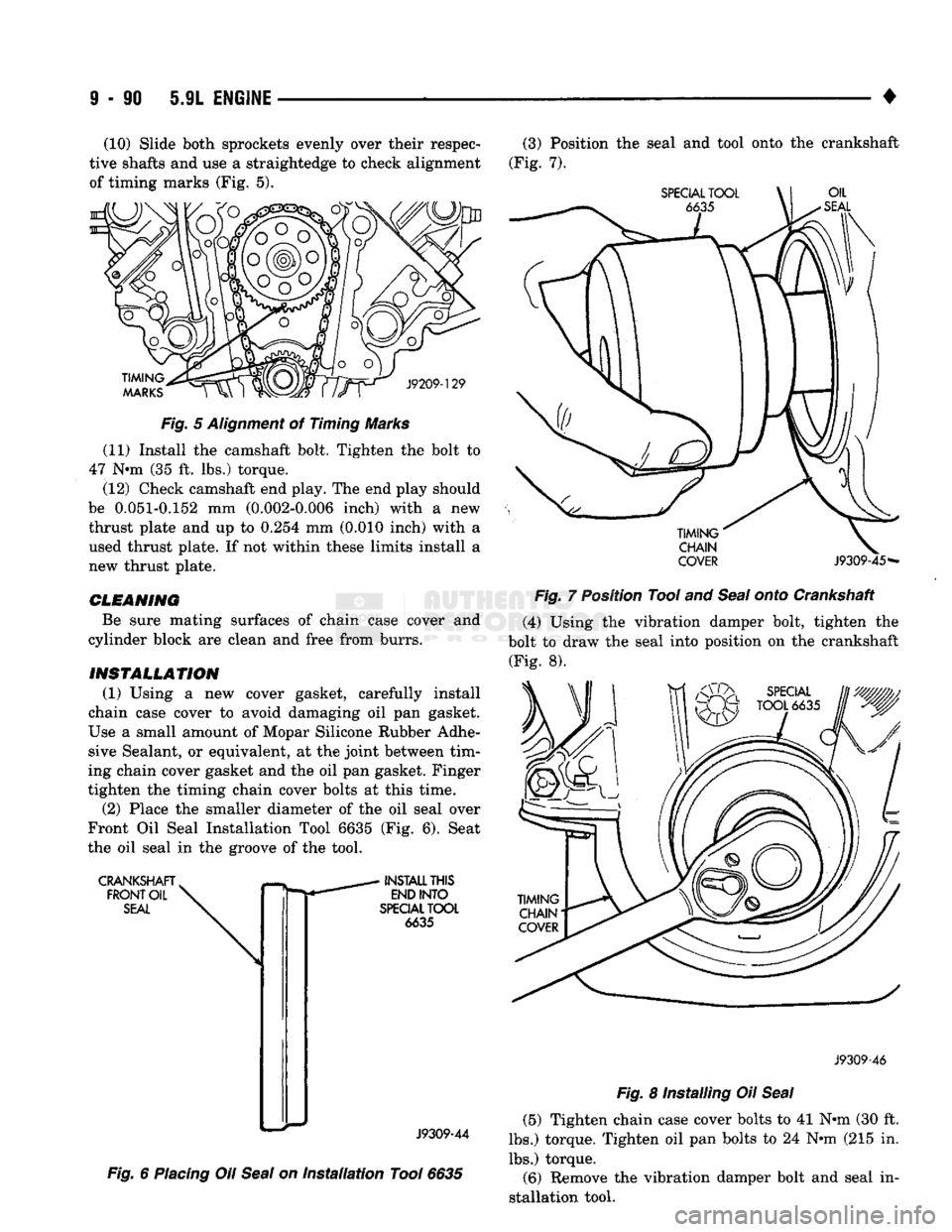
• (10) Slide both sprockets evenly over their respec
tive shafts and use a straightedge to check alignment
of timing marks (Fig. 5).
TIMING
MARKS
J9209-129
Fig.
5
Alignment
of Timing Marks
(11) Install the camshaft bolt. Tighten the bolt to
47 N-m (35 ft. lbs.) torque.
(12) Check camshaft end play. The end play should
be 0.051-0.152 mm (0.002-0.006 inch) with a new thrust plate and up to 0.254 mm (0.010 inch) with a
used thrust plate. If not within these limits install a
new thrust plate.
CLEANING
Be sure mating surfaces of chain case cover and
cylinder block are clean and free from burrs.
INSTALLATION
(1) Using a new cover gasket, carefully install
chain case cover to avoid damaging oil pan gasket.
Use a small amount of Mopar Silicone Rubber Adhe sive Sealant, or equivalent, at the joint between tim
ing chain cover gasket and the oil pan gasket. Finger
tighten the timing chain cover bolts at this time.
(2) Place the smaller diameter of the oil seal over
Front Oil Seal Installation Tool 6635 (Fig. 6). Seat
the oil seal in the groove of the tool.
CRANKSHAFT.
FRONT
OIL
SEAL
INSTALL
THIS
END
INTO
SPECIAL
TOOL
6635
J9309-44
Fig.
6
Placing
Oil
Seal
on
Installation
Tool
6635
(3) Position the seal and tool onto the crankshaft
(Fig. 7).
SPECIAL
TOOL
OIL
SEAL
TIMING'
CHAIN
COVER
J9309-45-
Fig.
7 Position Tool and
Seal
onto Crankshaft
(4) Using the vibration damper bolt, tighten the
bolt to draw the seal into position on the crankshaft (Fig. 8).
J9309-46
Fig.
8 Installing Oil
Seal
(5) Tighten chain case cover bolts to 41 N-m (30 ft.
lbs.) torque. Tighten oil pan bolts to 24 N»m (215 in.
lbs.) torque. (6) Remove the vibration damper bolt and seal in
stallation tool.
Page 697 of 1502
9
- 92 5.9L
ENGINE
•
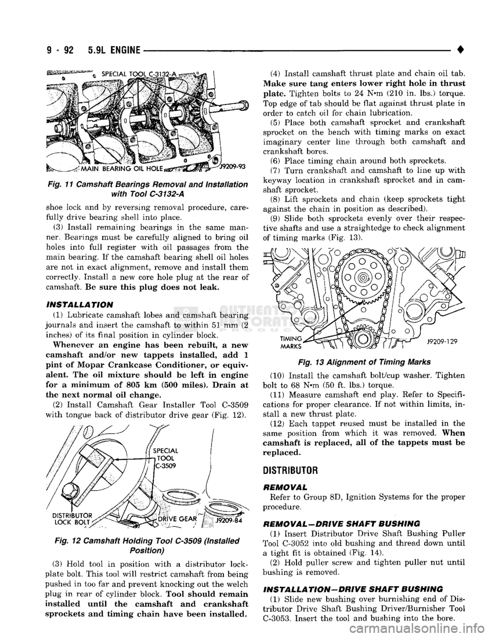
Fig.
11 Camshaft
Bearings
Removal
and
Installation
with Tool
C-3132-A
shoe lock and by reversing removal procedure, care
fully drive bearing shell into place. (3) Install remaining bearings in the same man
ner. Bearings must be carefully aligned to bring oil
holes into full register with oil passages from the main bearing. If the camshaft bearing shell oil holes
are not in exact alignment, remove and install them
correctly. Install a new core hole plug at the rear of
camshaft. Be sure this plug does not leak.
INSTALLATION (1) Lubricate camshaft lobes and camshaft bearing
journals and insert the camshaft to within 51 mm (2 inches) of its final position in cylinder block.
Whenever an engine has been rebuilt, a new
camshaft and/or new tappets installed, add 1
pint of Mopar Crankcase Conditioner, or equiv alent. The oil mixture should be left in engine
for a minimum of 805 km (500 miles). Drain at
the next normal oil change.
(2)
Install Camshaft Gear Installer Tool C-3509
with tongue back of distributor drive gear (Fig. 12).
Fig.
12 Camshaft
Holding
Tool C-3509 (Installed
Position)
(3) Hold tool in position with a distributor lock-
plate bolt. This tool will restrict camshaft from being
pushed in too far and prevent knocking out the welch
plug in rear of cylinder block. Tool should remain
installed until the camshaft and crankshaft sprockets and timing chain have been installed. (4) Install camshaft thrust plate and chain oil tab.
Make sure tang enters lower right hole in thrust
plate. Tighten bolts to 24 N-m (210 in. lbs.) torque.
Top edge of tab should be flat against thrust plate in
order to catch oil for chain lubrication.
(5) Place both camshaft sprocket and crankshaft
sprocket on the bench with timing marks on exact
imaginary center line through both camshaft and
crankshaft bores. (6) Place timing chain around both sprockets.
(7) Turn crankshaft and camshaft to line up with
keyway location in crankshaft sprocket and in cam shaft sprocket. (8) Lift sprockets and chain (keep sprockets tight
against the chain in position as described). (9) Slide both sprockets evenly over their respec
tive shafts and use a straightedge to check alignment of timing marks (Fig. 13).
Fig.
13
Alignment
of Timing Marks
(10) Install the camshaft bolt/cup washer. Tighten
bolt to 68 N-m (50 ft. lbs.) torque.
(11) Measure camshaft end play. Refer to Specifi
cations for proper clearance. If not within limits, in stall a new thrust plate.
(12) Each tappet reused must be installed in the
same position from which it was removed. When
camshaft is replaced, all of the tappets must be
replaced.
DISTRIBUTOR
REMOVAL Refer to Group 8D, Ignition Systems for the proper
procedure.
REMOVAL-DRIVE SHAFT BUSHING (1) Insert Distributor Drive Shaft Bushing Puller
Tool C-3052 into old bushing and thread down until a tight fit is obtained (Fig. 14).
(2) Hold puller screw and tighten puller nut until
bushing is removed.
INSTALLATION-DRIVE SHAFT BUSHING (1) Slide new bushing over burnishing end of Dis
tributor Drive Shaft Bushing Driver/Burnisher Tool
C-3053.
Insert the tool and bushing into the bore.
Page 724 of 1502
•
5.9L (DIESEL) ENGINE
9 - 119
INTEGRAL VALWE SEAT GRINDING
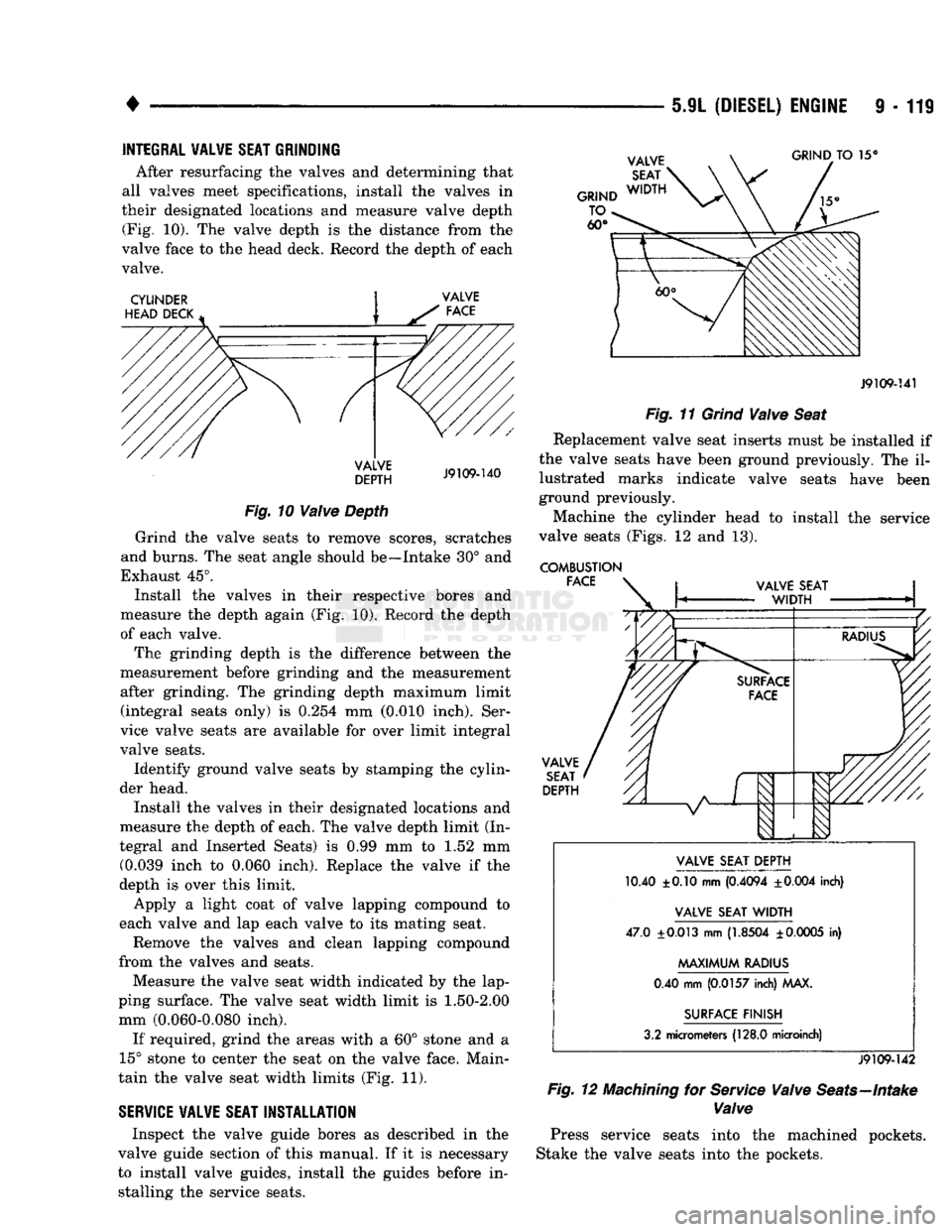
After resurfacing the valves and determining that
all valves meet specifications, install the valves in
their designated locations and measure valve depth (Fig. 10). The valve depth is the distance from the
valve face to the head deck. Record the depth of each valve.
CYLINDER
HEAD DECK GRIND
TO 15°
VALVE
DEPTH
J9109-140
Fig.
10
Valve
Depth
Grind the valve seats to remove scores, scratches
and burns. The seat angle should be—Intake 30° and
Exhaust 45°. Install the valves in their respective bores and
measure the depth again (Fig. 10). Record the depth
of each valve.
The grinding depth is the difference between the
measurement before grinding and the measurement after grinding. The grinding depth maximum limit (integral seats only) is 0.254 mm (0.010 inch). Ser
vice valve seats are available for over limit integral
valve seats.
Identify ground valve seats by stamping the cylin
der head.
Install the valves in their designated locations and
measure the depth of each. The valve depth limit (In
tegral and Inserted Seats) is 0.99 mm to 1.52 mm (0.039 inch to 0.060 inch). Replace the valve if the
depth is over this limit.
Apply a light coat of valve lapping compound to
each valve and lap each valve to its mating seat.
Remove the valves and clean lapping compound
from the valves and seats.
Measure the valve seat width indicated by the lap
ping surface. The valve seat width limit is
1.50-2.00
mm (0.060-0.080 inch).
If required, grind the areas with a 60° stone and a
15° stone to center the seat on the valve face. Main
tain the valve seat width limits (Fig. 11).
SERVICE
VALVE
SEAT
INSTALLATION
Inspect the valve guide bores as described in the
valve guide section of this manual. If it is necessary
to install valve guides, install the guides before in stalling the service seats.
J9109-141
Fig.
11
Grind
Valve
Seat
Replacement valve seat inserts must be installed if
the valve seats have been ground previously. The il lustrated marks indicate valve seats have been
ground previously.
Machine the cylinder head to install the service
valve seats (Figs. 12 and 13).
COMBUSTION FACE VALVE
SEAT
DEPTH VALVE SEAT DEPTH
10.40 ±0.10 mm
(0.4094
±0.004
inch)
VALVE SEAT
WIDTH
47.0
±0.013
mm
(1.8504
±
0.0005
in)
MAXIMUM
RADIUS
0.40 mm
(0.0157
inch) MAX.
SURFACE FINISH
3.2 micrometers
(128.0
microinch)
J9109-142
Fig.
12
Machining
for
Service
Valve
Seats—Intake
Valve
Press service seats into the machined pockets.
Stake the valve seats into the pockets.
Page 725 of 1502
9
- 120 5.9L
(DIESEL)
ENGINE
•
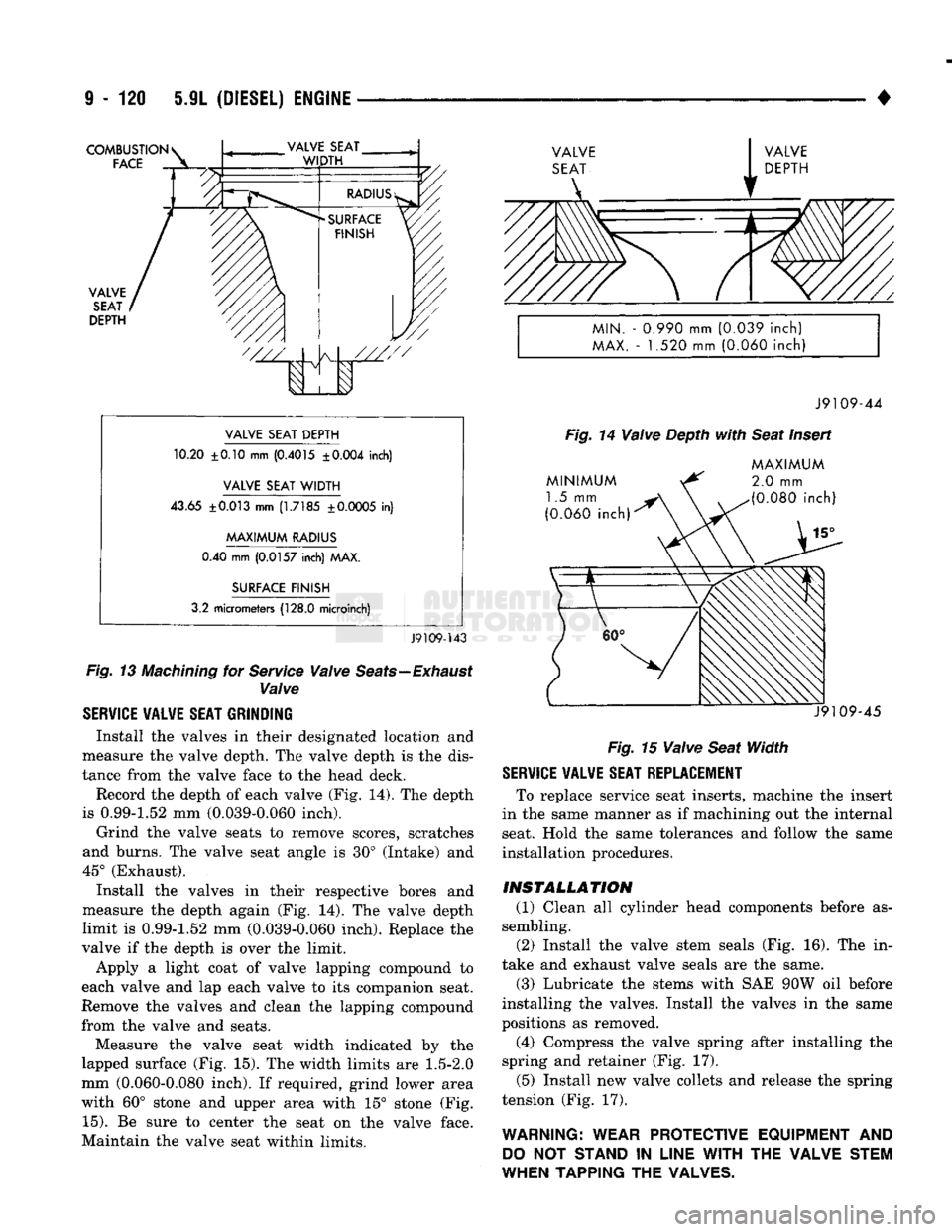
COMBUSTION
FACE
VALVE
SEAT
DEPTH
'///
A
I
V
1
VALVE
SEAT
DEPTH
10.20 ±0.10 mm
(0.4015
±0.004
inch)
VALVE
SEAT
WIDTH
43.65
±0.013
mm
(1.7185
±0.0005
in)
MAXIMUM
RADIUS
0.40 mm
(0.0157
inch) MAX.
SURFACE
FINISH
3.2 micrometers
(128.0
microinch)
J9109-143
Fig.
13
Machining
for
Service
Valve
Seats—Exhaust
Valve
SERVICE VALVE SEAT GRINDING
Install the valves in their designated location and
measure the valve depth. The valve depth is the dis
tance from the valve face to the head deck. Record the depth of each valve (Fig. 14). The depth
is 0.99-1.52 mm (0.039-0.060 inch).
Grind the valve seats to remove scores, scratches
and burns. The valve seat angle is 30° (Intake) and
45° (Exhaust). Install the valves in their respective bores and
measure the depth again (Fig. 14). The valve depth
limit is 0.99-1.52 mm (0.039-0.060 inch). Replace the
valve if the depth is over the limit.
Apply a light coat of valve lapping compound to
each valve and lap each valve to its companion seat.
Remove the valves and clean the lapping compound
from the valve and seats.
Measure the valve seat width indicated by the
lapped surface (Fig. 15). The width limits are
1.5-2.0
mm (0.060-0.080 inch). If required, grind lower area
with 60° stone and upper area with 15° stone (Fig.
15).
Be sure to center the seat on the valve face.
Maintain the valve seat within limits.
MIN.
-
0.990
mm
(0.039
inch)
MAX.
- 1.520 mm
(0.060
inch)
J9109-44
Fig.
14
Valve
Depth
with
Seat
Insert
MINIMUM
1.5 mm
(0.060
inch)
MAXIMUM
2.0
mm
(0.080
inch)
J9109-45
Fig.
15
Valve
Seat
Width
SERVICE VALVE SEAT REPLACEMENT
To replace service seat inserts, machine the insert
in the same manner as if machining out the internal
seat. Hold the same tolerances and follow the same
installation procedures.
INSTALLATION
(1) Clean all cylinder head components before as
sembling.
(2) Install the valve stem seals (Fig. 16). The in
take and exhaust valve seals are the same.
(3) Lubricate the stems with SAE 90W oil before
installing the valves. Install the valves in the same
positions as removed.
(4) Compress the valve spring after installing the
spring and retainer (Fig. 17).
(5) Install new valve collets and release the spring
tension (Fig. 17).
WARNING: WEAR PROTECTIVE EQUIPMENT
AND
DO
NOT
STAND
IN
LINE
WITH
THE VALVE STEM
WHEN TAPPING THE VALVES.