1993 DODGE TRUCK ESP
[x] Cancel search: ESPPage 1135 of 1502
21
- 134
IN-WEHiCLE SER¥iCE-32RH/3IRH/37RH/42RH/46RH
• • On 36RH/37RH746RH, back off adjusting screw
two turns. (6) Hold adjusting screw in place with backup
wrench. Then tighten locknut to 34 N*m (25 ft. lbs.) torque.
(7) Position new gasket on oil pan and install pan
on transmission. Tighten pan bolts to 17 N»m (13 ft.
lbs.) torque.
(8) Lower vehicle and refill transmission with Mo
par ATF Plus, type 7176, or Dexron II™ fluid.
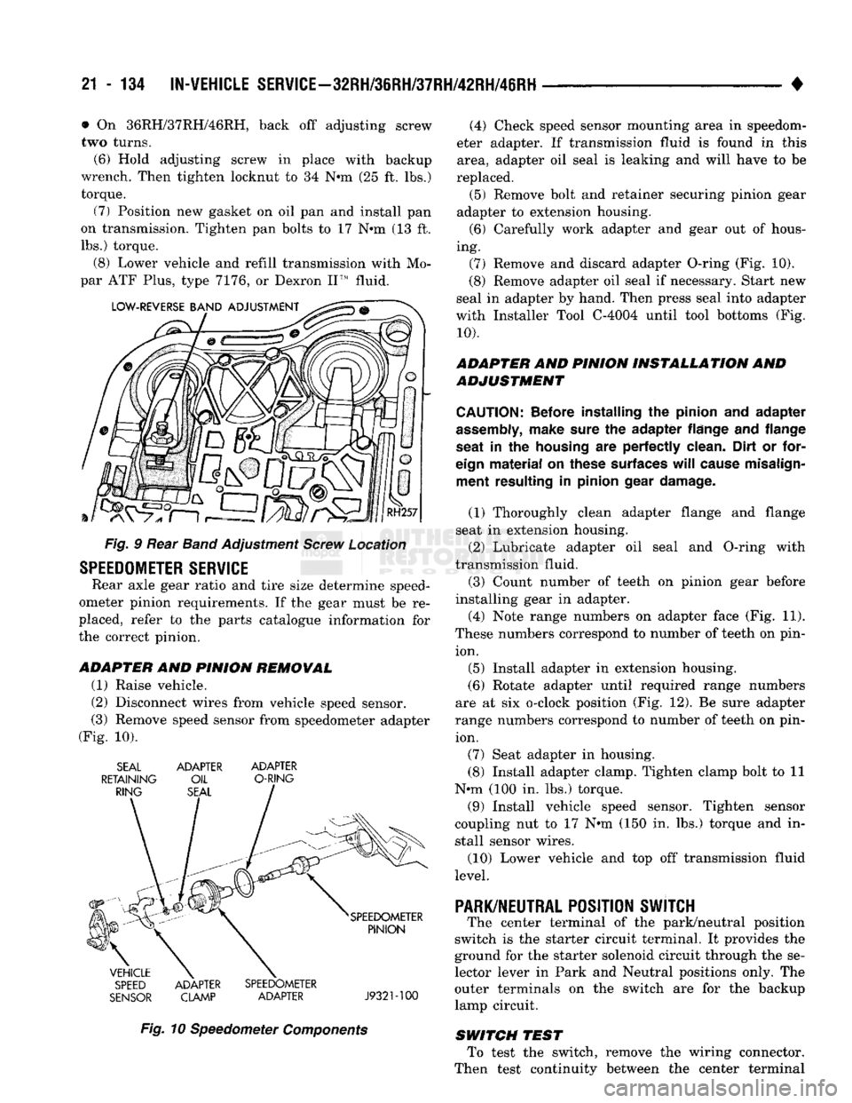
Fig. § Rear Band Adjustment Screw Location
SPEEDOMETER
SERVICE
Rear axle gear ratio and tire size determine speed
ometer pinion requirements. If the gear must be re
placed, refer to the parts catalogue information for
the correct pinion.
ADAPTER
AND
PINION REMOWAL
(1) Raise vehicle.
(2) Disconnect wires from vehicle speed sensor.
(3) Remove speed sensor from speedometer adapter
(Fig. 10). SEAL ADAPTER ADAPTER
RETAINING OIL O-RING
SPEED ADAPTER SPEEDOMETER
SENSOR CLAMP ADAPTER J932M00
Fig. 10 Speedometer Components (4) Check speed sensor mounting area in speedom
eter adapter. If transmission fluid is found in this area, adapter oil seal is leaking and will have to be
replaced. (5) Remove bolt and retainer securing pinion gear
adapter to extension housing. (6) Carefully work adapter and gear out of hous
ing. (7) Remove and discard adapter O-ring (Fig. 10).
(8) Remove adapter oil seal if necessary. Start new
seal in adapter by hand. Then press seal into adapter
with Installer Tool C-4004 until tool bottoms (Fig.
10).
ADAPTER AND PINION INSTALLATION AND
ADJUSTMENT
CAUTION:
Before installing
the
pinion
and
adapter
assembly,
make sure
the
adapter flange
and
flange
seat
in the
housing
are
perfectly clean. Dirt
or
for
eign
material
on
these surfaces
will
cause misalign ment resulting
in
pinion gear damage.
(1) Thoroughly clean adapter flange and flange
seat in extension housing.
(2) Lubricate adapter oil seal and O-ring with
transmission fluid.
(3) Count number of teeth on pinion gear before
installing gear in adapter.
(4) Note range numbers on adapter face (Fig. 11).
These numbers correspond to number of teeth on pin ion.
(5) Install adapter in extension housing.
(6) Rotate adapter until required range numbers
are at six o-clock position (Fig. 12). Be sure adapter
range numbers correspond to number of teeth on pin ion.
(7) Seat adapter in housing.
(8) Install adapter clamp. Tighten clamp bolt to 11
N*m (100 in. lbs.) torque.
(9) Install vehicle speed sensor. Tighten sensor
coupling nut to 17 N*m (150 in. lbs.) torque and in
stall sensor wires.
(10) Lower vehicle and top off transmission fluid
level.
PARK/NEUTRAL
POSITION SWJTCH
The center terminal of the park/neutral position
switch is the starter circuit terminal. It provides the
ground for the starter solenoid circuit through the se
lector lever in Park and Neutral positions only. The
outer terminals on the switch are for the backup
lamp circuit.
SWITCH TEST To test the switch, remove the wiring connector.
Then test continuity between the center terminal
Page 1172 of 1502
TRANSMISSION
OVERHAUL—32RH
21 - 171
PLANETARY GEAR TRAIN
OVERHAUL
•OUTPUT
SHAFT
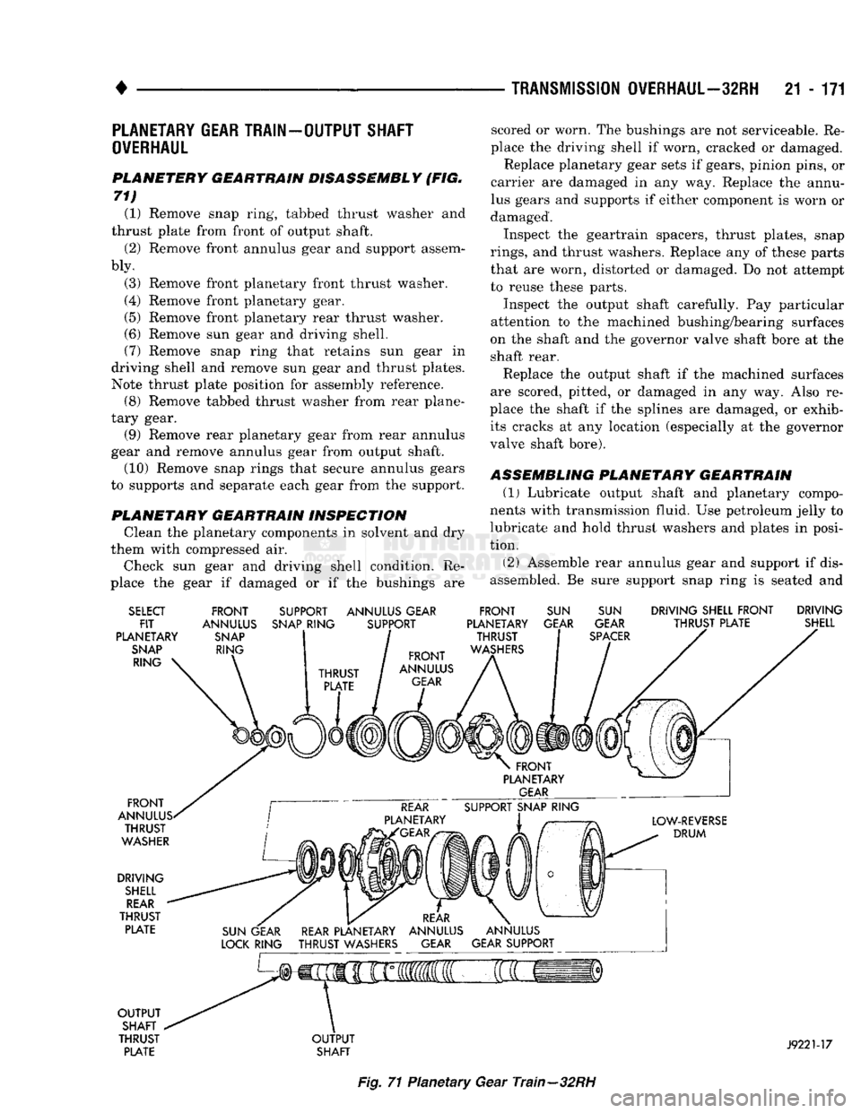
PLANETERY GEARTRAIN DISASSEMBLY (FIG.
71) (1) Remove snap ring, tabbed thrust washer and
thrust plate from front of output shaft.
(2) Remove front annulus gear and support assem
bly.
(3) Remove front planetary front thrust washer.
(4) Remove front planetary gear.
(5) Remove front planetary rear thrust washer.
(6) Remove sun gear and driving shell.
(7) Remove snap ring that retains sun gear in
driving shell and remove sun gear and thrust plates.
Note thrust plate position for assembly reference. (8) Remove tabbed thrust washer from rear plane
tary gear. (9) Remove rear planetary gear from rear annulus
gear and remove annulus gear from output shaft. (10) Remove snap rings that secure annulus gears
to supports and separate each gear from the support.
PLANETARY GEARTRAIN INSPECTION Clean the planetary components in solvent and dry
them with compressed air.
Check sun gear and driving shell condition. Re
place the gear if damaged or if the bushings are scored or worn. The bushings are not serviceable. Re
place the driving shell if worn, cracked or damaged. Replace planetary gear sets if gears, pinion pins, or
carrier are damaged in any way. Replace the annu
lus gears and supports if either component is worn or
damaged.
Inspect the geartrain spacers, thrust plates, snap
rings,
and thrust washers. Replace any of these parts
that are worn, distorted or damaged. Do not attempt
to reuse these parts.
Inspect the output shaft carefully. Pay particular
attention to the machined bushing/bearing surfaces
on the shaft and the governor valve shaft bore at the
shaft rear.
Replace the output shaft if the machined surfaces
are scored, pitted, or damaged in any way. Also re
place the shaft if the splines are damaged, or exhib its cracks at any location (especially at the governor
valve shaft bore).
ASSEMBLING PLANETARY GEARTRAIN
(1)
Lubricate output shaft and planetary compo
nents with transmission fluid. Use petroleum jelly to
lubricate and hold thrust washers and plates in posi
tion.
(2) Assemble rear annulus gear and support if dis
assembled. Be sure support snap ring is seated and
SELECT
FIT
PLANETARY
SNAP
RING FRONT
ANNULUS
SNAP
RING SUPPORT ANNULUS GEAR
SNAP
RING SUPPORT FRONT
PLANETARY THRUST
WASHERS
SUN
GEAR
SUN
GEAR
SPACER
DRIVING SHELL FRONT DRIVING
THRUST PLATE SHELL
FRONT
ANNULUS. THRUST
WASHER
DRIVING
SHELL
REAR
THRUST PLATE
OUTPUT
SHAFT
THRUST PLATE
OUTPUT
SHAFT
J9221-17
Fig.
71 Planetary Gear Train—32RH
Page 1354 of 1502
•
NP241 TRANSFER
CASE
21 - 313
LOCK OIL RING SEAL
ADAPTER
(OVERDRIVE
ONLY)
SPEEDOMETER
PINION
GEAR
ADAPTER
O-RING
SPEEDOMETER
ADAPTER
RETAINER
DISTANCE
SENSOR
J9021-99
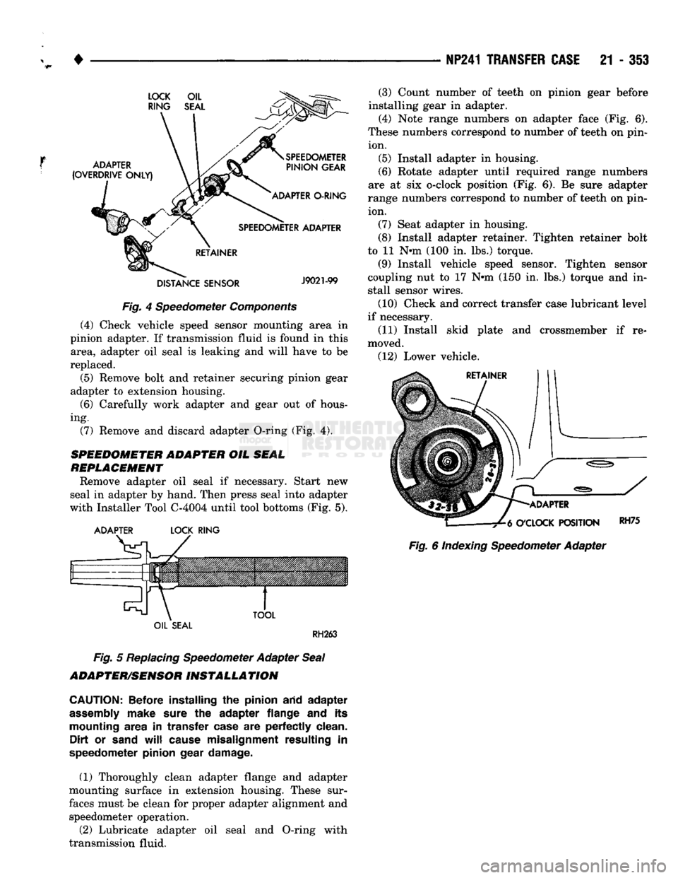
Fig.
4 Speedometer
Components
(4) Check vehicle speed sensor mounting area in
pinion adapter. If transmission fluid is found in this area, adapter oil seal is leaking and will have to be
replaced.
(5) Remove bolt and retainer securing pinion gear
adapter to extension housing.
(6)
Carefully work adapter and gear out of hous
ing. (7) Remove and discard adapter O-ring (Fig. 4).
SPEEDOMETER ADAPTER
OIL
SEAL
REPLACEMENT
Remove adapter oil seal if necessary. Start new
seal in adapter by hand. Then press seal into adapter
with Installer Tool C-4004 until tool bottoms (Fig. 5).
ADAPTER
LOCK
RING
TOOL
(3) Count number of teeth on pinion gear before
installing gear in adapter.
(4) Note range numbers on adapter face (Fig. 6).
These numbers correspond to number of teeth on pin ion. (5) Install adapter in housing.
(6)
Rotate adapter until required range numbers
are at six o-clock position (Fig. 6). Be sure adapter
range numbers correspond to number of teeth on pin ion. (7) Seat adapter in housing.
(8) Install adapter retainer. Tighten retainer bolt
to 11 N-m (100 in. lbs.) torque.
(9) Install vehicle speed sensor. Tighten sensor
coupling nut to 17 N-m (150 in. lbs.) torque and in
stall sensor wires.
(10) Check and correct transfer case lubricant level
if necessary.
(11) Install skid plate and crossmember if re
moved. (12) Lower vehicle.
ADAPTER
O'CLOCK
POSITION
Fig.
6 Indexing Speedometer Adapter
RH75
OIL
SEAL
RH263
Fig.
5
Replacing
Speedometer Adapter
Seal
ADAPTER/SENSOR
INSTALLATION
CAUTION:
Before installing
the
pinion arid adapter
assembly
make sure
the
adapter flange
and its
mounting area
in
transfer case
are
perfectly clean. Dirt
or
sand
will
cause misalignment resulting
in
speedometer pinion gear damage.
(1) Thoroughly clean adapter flange and adapter
mounting surface in extension housing. These sur
faces must be clean for proper adapter alignment and speedometer operation.
(2) Lubricate adapter oil seal and O-ring with
transmission fluid.
Page 1366 of 1502
•
TRANSMISSION/TRANSFER CASE SPECIFICATIONS
21 - 365
411H
mm
Front Clutch Thrust Washer
(on reaction shaft support
hub)
.016
in.
.061
in.
.084
in.
.102
in.
Rear Clutch Thrust Washer
(on clutch retainer) .061
in.
.061
in.
Intermediate Shaft Thrust Plate
(on shaft pilot
hub)
.060-.063
in.
.060-.063
in.
Output Shaft Thrust Washer (in rear clutch
hub)
.068-.070
in.
.052-.054
in.
.068-.070
in.
.083-.085
in.
Rear Clutch
Pack
Snap Ring .060
in.
.076
in.
.098
in.
.060
in.
.074
in.
Planetary Geartrain Snap Ring
(at front
end of
intermediate shaft) .062
in.
.074
in.
.055-059
in.
.062-.066
in.
Overdrive Piston Thrust Plate Thrust plate
and
spacer
are
select
fit
components. Refer
to
size charts
and
selection procedures
in
"Overdrive Unit
Assembly
and
Adjustment."
Intermediate Shaft Spacer
Thrust plate
and
spacer
are
select
fit
components. Refer
to
size charts
and
selection procedures
in
"Overdrive Unit
Assembly
and
Adjustment."
J9221-143
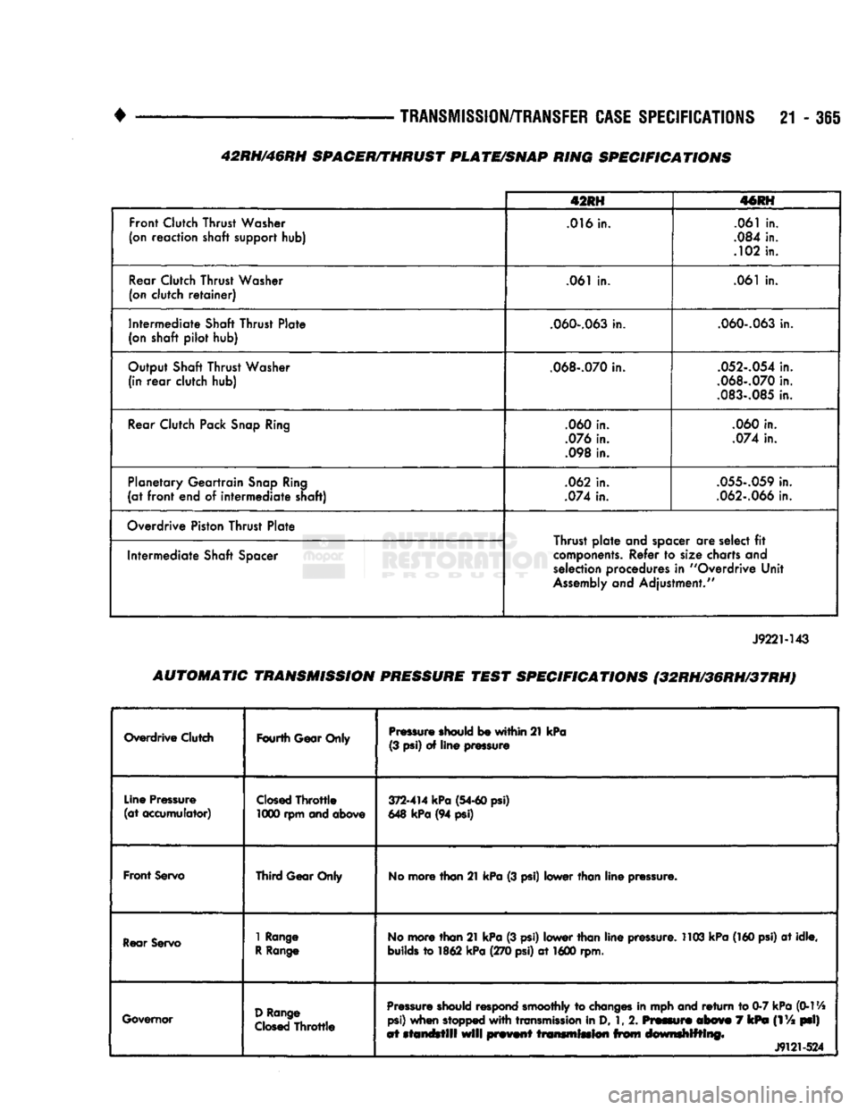
AUTOMATIC TRANSMISSION PRESSURE TEST SPECIFICATIONS (32RH/36RH/37RH)
Overdrive Clutch
Fourth
Gear Only
Pressure
should be
within
21
kPa
(3
psi)
of
line
pressure
Line
Pressure
(at
accumulator)
Closed
Throttle
1000 rpm and above
372-414
kPa
(54-60
psi)
648
kPa
(94 psi)
Front
Servo
Third
Gear Only No
more than 21 kPa
(3
psi) lower than line
pressure.
Rear
Servo 1 Range
R
Range No
more than 21 kPa
(3
psi) lower than line
pressure.
1103 kPa
(160
psi)
at
idle,
builds
to
1862 kPa (270
psi)
at
1600 rpm.
Governor
D
Range
Closed
Throttle
Pressure
should
respond smoothly to changes in mph
and
return to
0-7
kPa
(0-114
psi)
when stopped
with
transmission
in D,
1,
2.
Pmmmf®
mb&wm
7
kPm
(1
Va
psi)
at
standstill
will
prmnf transmission from drnwrnhlfflmg*
J9121-524
42RH/46RH SPACER/THRUST PLATE/SNAP RING SPECIFICATIONS
Page 1367 of 1502
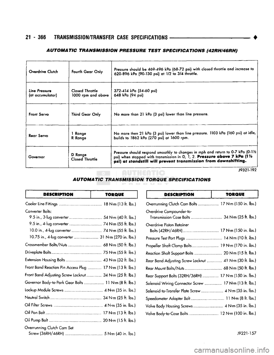
21 • 366
TRANSMISSION/TRANSFER
CASE
SPECIFICATIONS
•
Overdrive Clutch
Fourth Gear Only Pressure should be
469-496
kPa
(68-72
psi) with closed throttle and increase to
620-896
kPa
(90-130
psi) at 1/2 to 3/4 throttle.
Line Pressure
(at accumulator) Closed Throttle
1000
rpm and above
372-414
kPa
(54-60
psi)
648 kPa (94 psi)
Front Servo Third Gear Only No more than
21
kPa (3 psi) lower than line pressure.
Rear Servo
1
Range
R Range No more then
21
kPa (3 psi) lower than line pressure. 1103 kPa (160 psi) at idle,
builds to 1862 kPa (270 psi) at 1600 rpm.
Governor D Range
Closed Throttle Pressure should respond smoothly to changes in mph and return to 0-7 kPa
(0-1
Vi
psi) when stopped with transmission in D,
1,
2. Pressure
above
7
kPa
(IV2
psi)
at
standstill
will
prevent
transmission
from
downshifting.
J9321-192
AUTOMATIC
TRANSMISSION
TORQUE
SPECIFICATIONS
DESCRIPTION TORQUE DESCRIPTION TORQUE
Cooler Line Fittings 18 N-m (13 ft. lbs.)
Converter Bolts: 9.5 in.,
3-lug
converter 54 N-m (40 ft. lbs.
9.5 in., 4-lug converter 74 N-m (55 ft. lbs. 10.0 in., 4-lug converter 74 N-m (55 ft. lbs.
10.75 in., 4-lug converter 31 N-m (270 in. lbs.
Crossmember Bolts/Nuts 68 N-m (50 ft. lbs. Driveplate Bolts 75 N-m (55 ft. lbs.
Extension Housing Bolts 43 N-m (32 ft. lbs.
Front Band Reaction Pin Access Plug 17 N-m (13 ft. lbs.
Front Band Adjusting Screw Locknut 34 N-m (25 ft. lbs.
Governor Body-to-Park Gear Bolts 11 N-m (8 ft. lbs.
Lockup Module Screws 4 N-m (35 in. lbs.
Neutral Switch 34 N-m (25 ft. lbs.
Oil Filter Screws 4 N-m (35 in. lbs.
Oil Pan Bolt 17 N-m (13 ft. lbs.
Oil Pump Bolt 20 N-m (15 ft. lbs.
Overrunning Clutch Cam Set Screw (36RH/46RH) 5 N-m (40 in. lbs. Overrunning Clutch Cam Bolts 17 N-m (150 in. lbs.
Overdrive Compounder-to- Transmission Case Bolts 34 N-m (25 ft. lbs.
Overdrive Piston Retainer Bolts (42RH/46RH) 17 N-m (150 in. lbs.
Pressure Test Port Plugs 14 N-m (10 ft. lbs.
Propeller Shaft Clamp Bolts 19 N-m (170 in. lbs.
Reaction Shaft Support Bolts 20 N-m (15 ft. lbs.
Rear
Band
Adjusting Screw Locknut 41 N-m (30 ft. lbs.
Rear Mount Bolts/Nuts 68 N-m (50 ft. lbs.
Rear Support Bolts (32RH/36RH) 17 N-m (150 in. lbs.
Solenoid Wiring Connector Screw 17 N-m (13 ft. lbs.
Solenoid-to-Transfer Plate Screw 4 N-m (35 in. lbs.
Speedometer Adapter Bolt 11 N-m (8 ft. lbs.
Valve Body Housing Screws 4 N-m (35 in. lbs.
Valve Body-to-Case Bolts 12 N-m (100 in. lbs.
J9221-157
AUTOMATIC TRANSMISSION PRESSURE TEST SPECIFICATIONS (42RH/46RH)
Page 1372 of 1502
•
WHEELS
AND
TIRES
22 - 3 • Noise
• Handling
• Durability
• Tread life
• Traction
• Rolling resistance
• Speed capability
We recommend that tires equivalent to the original
equipment tires be used when replacement is needed. Refer to the placard on the vehicle or the
Owner's Manual for the correct replacement
tire.
Failure to use original equipment replacement
tires may adversely affect the handling of the vehi
cle.
The use of oversize tires is not
recommended.
They may cause interference with vehicle suspension and steering travel. This can cause tire damage or
failure.
WARNING: FAILURE
TO
EQUIP
THE
VEHICLE
WITH
TIRES
HAVING ADEQUATE LOAD CAPABILITY
CAN
RESULT
IN
SUDDEN TIRE FAILURE.
ROTATION
Tires on the front and rear axles operate at differ
ent loads and perform different steering, driving, and
braking functions. For these reasons; • They wear at unequal rates
• Tend to develop irregular wear patterns These effects can be reduced by timely rotation of
tires.
The benefits of rotation are especially worth
while. Rotation will: • Increase tread life
• Help to maintain mud, snow, and wet traction levels
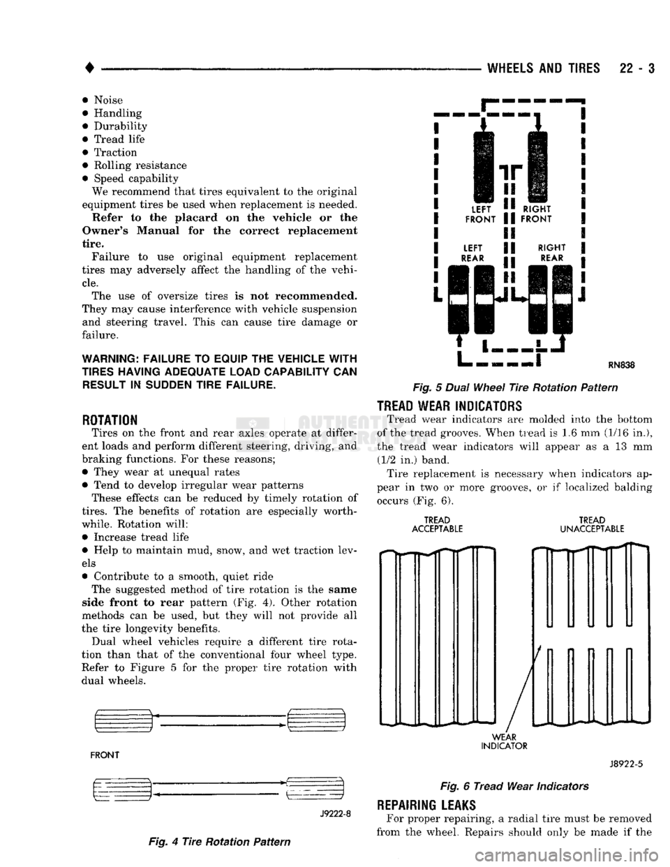
• Contribute to a smooth, quiet ride The suggested method of tire rotation is the
same
side front
to
rear
pattern (Fig. 4). Other rotation
methods can be used, but they will not provide all
the tire longevity benefits. Dual wheel vehicles require a different tire rota
tion than that of the conventional four wheel type.
Refer to Figure 5 for the proper tire rotation with
dual wheels.
FRONT m kz
—~i
J9222-8 LEFT
'I
RIGHT
FRONT
II
FRONT
LEFT
II
RIGHT
REAR
p
REAR
1
|| | L HN838
Fig.
5
Dual
Wheel
Tire
Rotation
Pattern
TREAD
WEAR INDICATORS Tread
wear indicators are molded into the bottom
of the tread grooves. When
tread
is 1.6 mm (1/16 in.),
the tread wear indicators will appear as a 13 mm (1/2 in.) band. Tire replacement is necessary when indicators ap
pear in two or more grooves, or if localized balding occurs (Fig. 6).
TREAD
ACCEPTABLE TREAD
UNACCEPTABLE
WEAR
INDICATOR
v
J8922-5
Fig.
4
Tire
Rotation
Pattern
Fig.
6
Tread
Wear Indicators
REPAIRING
LEAKS
For proper repairing, a radial tire must be removed
from the wheel. Repairs should only be made if the
Page 1437 of 1502
23 - 54
BODY COMPONENTS
•
REFINISHING PROCEDURES
SERVICE
INFORMATION
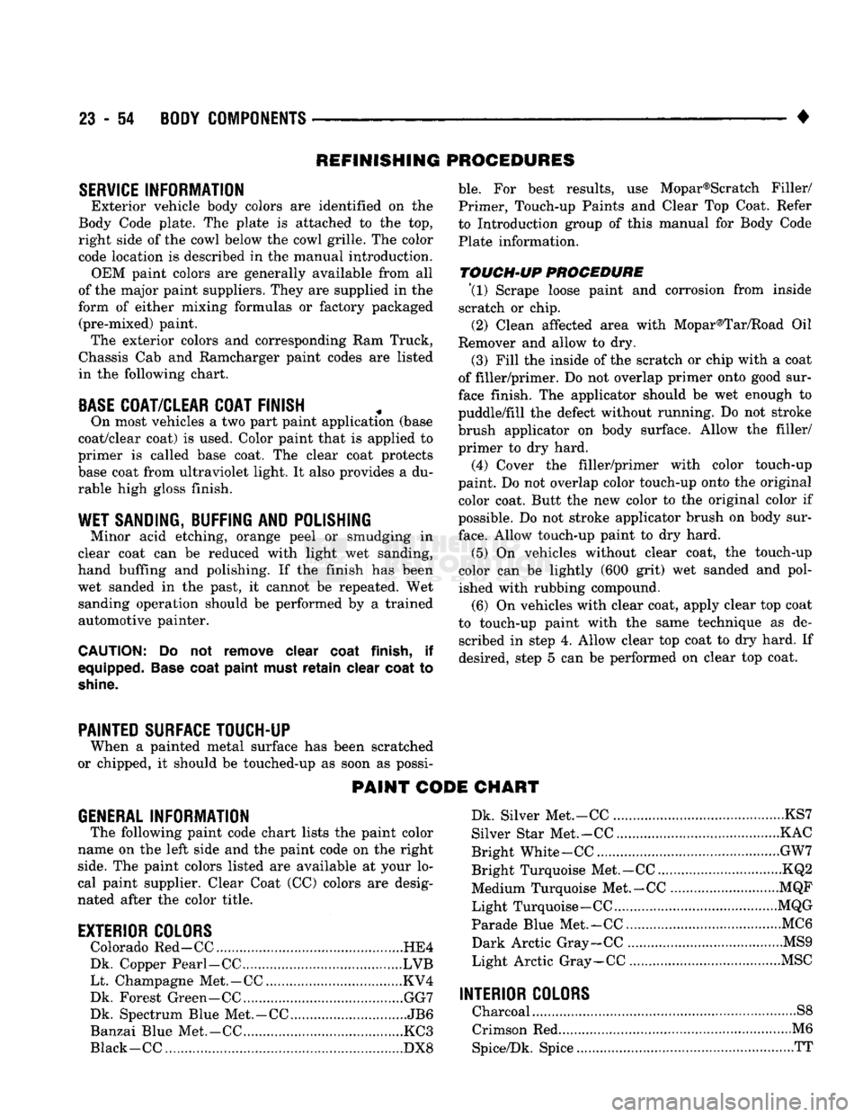
Exterior vehicle body colors are identified on the
Body Code plate. The plate is attached to the top, right side of the cowl below the cowl grille. The color
code location is described in the manual introduction. OEM paint colors are generally available from all
of the major paint suppliers. They are supplied in the
form of either mixing formulas or factory packaged (pre-mixed) paint. The exterior colors and corresponding Ram Truck,
Chassis Cab and Ramcharger paint codes are listed
in the following chart.
BASE
COAT/CLEAR COAT FINISH
On most vehicles a two part paint application (base
coat/clear coat) is used. Color paint that is applied to
primer is called base coat. The clear coat protects
base coat from ultraviolet light. It also provides a du
rable high gloss finish.
WET SANDING, BUFFING
AND
POLISHING
Minor acid etching, orange peel or smudging in
clear coat can be reduced with light wet sanding,
hand buffing and polishing. If the finish has been wet sanded in the past, it cannot be repeated. Wet sanding operation should be performed by a trained
automotive painter.
CAUTION:
Do not remove clear
coat
finish,
if
equipped.
Base
coat
paint
must
retain
clear
coat
to
shine.
ble.
For best results, use Mopar®Scratch Filler/
Primer, Touch-up Paints and Clear Top Coat. Refer
to Introduction group of this manual for Body Code
Plate information.
TOUCH-UP
PROCEDURE \l)
Scrape loose paint and corrosion from inside
scratch or chip.
(2) Clean affected area with Mopar®Tar/Road Oil
Remover and allow to dry.
(3) Fill the inside of the scratch or chip with a coat
of filler/primer. Do not overlap primer onto good sur
face finish. The applicator should be wet enough to
puddle/fill the defect without running. Do not stroke
brush applicator on body surface. Allow the filler/ primer to dry hard.
(4) Cover the filler/primer with color touch-up
paint. Do not overlap color touch-up onto the original color coat. Butt the new color to the original color if
possible. Do not stroke applicator brush on body sur
face.
Allow touch-up paint to dry hard.
(5) On vehicles without clear coat, the touch-up
color can be lightly (600 grit) wet sanded and pol
ished with rubbing compound.
(6) On vehicles with clear coat, apply clear top coat
to touch-up paint with the same technique as de scribed in step 4. Allow clear top coat to dry hard. If
desired, step 5 can be performed on clear top coat.
PAINTED SURFACE TOUCH-UP
When a painted metal surface has been scratched
or chipped, it should be touched-up as soon as possi-
PAINT CODE CHART
GENERAL
INFORMATION
The following paint code chart lists the paint color
name on the left side and the paint code on the right
side.
The paint colors listed are available at your lo
cal paint supplier. Clear Coat (CO colors are desig
nated after the color title.
EXTERIOR COLORS
Colorado Red-CC HE4
Dk. Copper Pearl-CC LVB Lt. Champagne Met.-CC KV4
Dk. Forest Green-CC GG7
Dk. Spectrum Blue Met.-CC JB6
Banzai Blue Met.-CC KC3
Black -CC DX8 Dk. Silver Met.-CC KS7
Silver Star Met.-CC KAC
Bright White-CC GW7
Bright Turquoise Met.-CC KQ2
Medium Turquoise Met.-CC MQF
Light Turquoise-CC MQG
Parade Blue Met.-CC... MC6
Dark Arctic Gray-CC MS9
Light Arctic Gray-CC MSC
INTERIOR COLORS
Charcoal S8
Crimson Red M6
Spice/Dk. Spice TT
Page 1449 of 1502
24-12
HEATING
AND AIR
CONDITIONING
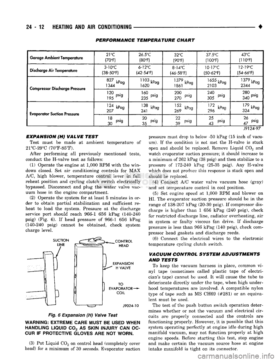
PERFORMANCE TEMPERATURE CHART
Garage
Ambient
Temperature
21
°C
(70°F) 26.5°C
(80°F) 32°C
(90°F) 3/.5°'J
(100T) 43°C
(110°F)
Discharge
Air Temperature
3-10°C
(38-50°F) 6-12°C
(42-54'F) 8-14°C
(46-58°F) 10-17°C
(50-62°F) 12-19°C
(54-66°F)
Compressor
Discharge Pressure
1344 a
1620 a
1861 kPag 2103 a 1379kPcg
2344 a
Compressor
Discharge Pressure
120 •
195 PS'9 160 .
235 PS'9 200 .
270 PS'9 240 .
305 PS'9 280 .
340 PS'9
Evaporator
Suction Pressure
124 kPag
207 a 138 kPag
241 J 269 kPag III kP°9
296 179 ,D
324 kPag
Evaporator
Suction Pressure
18 .
30 PS'9 20 .
35 pS'g 22
39 pS,g
25 .
43 pS'g 26 .
47 pS'9
J9124-97 pressure must drop to below -50 kPag (15 inch of vacu
um).
If the condition is not met the H-valve is stuck
open and should be replaced. Remove Liquid C02 and
watch evaporator suction pressure; it should increase to a minimum of 262 kPag (38 psig) and then stabilize to a
pressure of 172-240 kPag (25-35 psig). Any H-valve
which does not produce this response is stuck open and should be replaced.
(4) Connect A/C water valve vacuum hose (gray)
and set temperature control in cool position.
(5) Set engine speed at 1,000 RPM and blower on
HI.
The evaporator suction pressure should be in the
range of 138-207 kPag (20-30 psig). If compressor dis charge is higher than 1 656 kPag (240 psig), check
for restricted discharge line, radiator overheating, air in system or faulty viscous fan drive. If discharge
pressure is less than 966 kPag (140 psig), check com
pressor head gaskets and discharge reeds.
(6) Connect the electrical wires to the electronic
temperature cycling clutch switch.
VACUUM CONTROL SYSTEM ADJUSTMENTS
AND TESTS To keep the vacuum harness in place, common vi
nyl tape (sometimes called plastic tape of electri
cian's tape) cannot be used. It will cause the tube to
deteriorate directly under the tape, when high under
hood temperatures are involved. A compatible nylon type of tape such as MS CH69 (#281) or an equivalent must be used.
The test of the push button switch operation deter
mines whether or not the vacuum and electrical cir cuits are properly connected and the controls are
functioning properly. However, it is possible that this system operating perfectly at engine idle during high
manifold vacuum, may not function properly at high engine speeds. Before starting this test, stop engine and make certain the vacuum source hose at engine
intake manifold is tight on its connector.
EXPANSION (H) VALVE TEST
Test must be made at ambient temperature of
21°C-29°C (70°F-85°F).
After performing all previously mentioned tests,
conduct the H-valve test as follows:
(1) Operate the engine at 1,000 RPM with the win
dows closed. Set air conditioning controls for MAX
A/C,
high blower, temperature control lever in full
reheat position and cycling clutch switch electrically
bypassed. Disconnect and plug the water valve vac uum hose in the engine compartment. (2) Operate the system for at least 5 minutes in or
der to obtain partial stabilization and sufficient re
heat to load the system. Pressure at the discharge service port should reach 966-1 656 kPag (140-240
psig) (Fig. 6). If head pressure of 966-1 656 kPag (140-240 psig) cannot be obtained, check system
charge level.
Fig.
6
Expansion
(H)
Valve
Test
WARNING:
EXTREME
CARE
MUST
BE
USED
WHEN
HANDLING
LIQUID
C02 AS
SKIN
INJURY
CAN OC
CUR
IF
PROTECTIVE
GLOVES
ARE NOT
WORN.
(3) Put Liquid C02 on control head (completely cover
head) for a minimum of 30 seconds. Evaporator suction