1993 DODGE TRUCK ESP
[x] Cancel search: ESPPage 930 of 1502
•
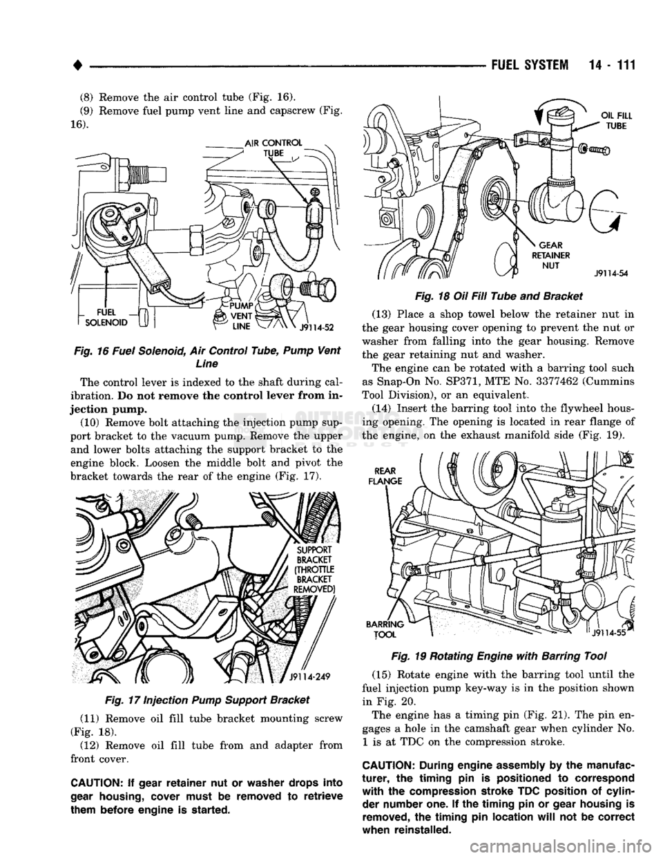
(8) Remove the air control tube (Fig. 16).
(9) Remove fuel pump vent line and capscrew (Fig.
16).
Fig.
16 Fuel Solenoid, Air Control Tube,
Pump
Vent Line
The control lever is indexed to the shaft during cal
ibration. Do not remove the control lever from in
jection pump. (10) Remove bolt attaching the injection pump sup
port bracket to the vacuum pump. Remove the upper and lower bolts attaching the support bracket to the
engine block. Loosen the middle bolt and pivot the
bracket towards the rear of the engine (Fig. 17).
Fig.
17 Injection
Pump
Support
Bracket
(11) Remove oil fill tube bracket mounting screw
(Fig. 18). (12) Remove oil fill tube from and adapter from
front cover.
CAUTION:
If
gear
retainer
nut or
washer drops into
gear
housing,
cover must
be
removed
to
retrieve
them before engine
is
started. FUEL
SYSTEM
14-111
Fig.
18 Oil Fill Tube and Bracket (13) Place a shop towel below the retainer nut in
the gear housing cover opening to prevent the nut or
washer from falling into the gear housing. Remove
the gear retaining nut and washer.
The engine can be rotated with a barring tool such
as Snap-On No.
SP371,
MTE No. 3377462 (Cummins
Tool Division), or an equivalent.
(14) Insert the barring tool into the flywheel hous
ing opening. The opening is located in rear flange of
the engine, on the exhaust manifold side (Fig. 19).
Fig.
19 Rotating
Engine
with
Barring Tool
(15) Rotate engine with the barring tool until the
fuel injection pump key-way is in the position shown in Fig. 20.
The engine has a timing pin (Fig. 21). The pin en
gages a hole in the camshaft gear when cylinder No. 1 is at TDC on the compression stroke.
CAUTION:
During
engine
assembly
by the
manufac
turer,
the
timing
pin is
positioned
to
correspond
with
the
compression stroke TDC position
of
cylin der number one.
If the
timing
pin or
gear housing
is
removed,
the
timing
pin
location
will
not be
correct
when reinstalled.
Page 936 of 1502
•
FUEL
SYSTEM
14-117
(5)
Bleed air from the fuel system. Refer to High
Pressure Fuel Lines in the Air Bleeding portion of
this section.
INJECTION
TIMING
If incorrect injection timing is suspected, injection
pump-to-engine timing or injection pump timing may
be the cause. Check injection pump timing before checking injection pump-to-engine timing.
INJECTION
PUMP
TIMING
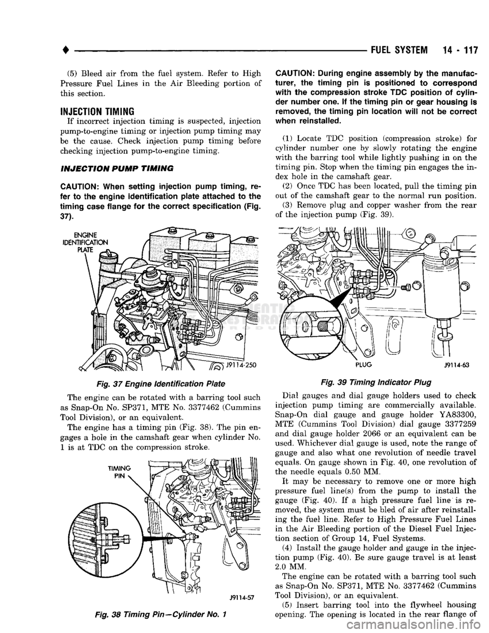
CAUTION;
When
setting
injection
pump
timing,
re
fer to the engine
identification
plate
attached
to the
timing
case
flange for the
correct
specification
(Fig.
37). Fig. 37
Engine
identification Plate
The engine can be rotated with a barring tool such
as Snap-On No.
SP371,
MTE No. 3377462 (Cummins
Tool Division), or an equivalent.
The engine has a timing pin (Fig. 38). The pin en
gages a hole in the camshaft gear when cylinder No.
1
is at TDC on the compression stroke.
J9114-57
Fig. 38
Timing
Pin—Cylinder
No. 1
CAUTION:
During engine
assembly
by the manufac
turer,
the
timing
pin is positioned to correspond
with
the compression stroke TDC position of cylinder number one. If the
timing
pin or
gear
housing
is
removed,
the
timing
pin
location
will
not be
correct
when reinstalled.
(1)
Locate TDC position (compression stroke) for
cylinder number one by slowly rotating the engine
with the barring tool while lightly pushing in on the
timing pin. Stop when the timing pin engages the in dex hole in the camshaft gear. (2) Once TDC has been located, pull the timing pin
out of the camshaft gear to the normal run position.
(3) Remove plug and copper washer from the rear
of the injection pump (Fig. 39).
PLUG
J9114-63
Fig. 39
Timing Indicator
Plug
Dial gauges and dial gauge holders used to check
injection pump timing are commercially available. Snap-On dial gauge and gauge holder YA83300,
MTE (Cummins Tool Division) dial gauge 3377259 and dial gauge holder 2066 or an equivalent can be
used. Whichever dial gauge is used, note the range of
gauge and also what one revolution of needle travel
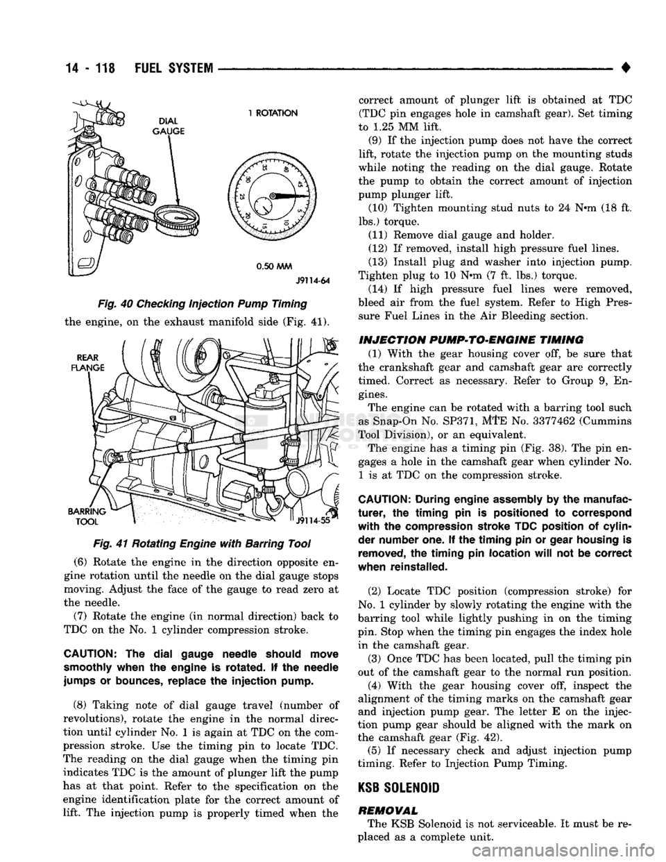
equals. On gauge shown in Fig. 40, one revolution of
the needle equals 0.50 MM.
It may be necessary to remove one or more high
pressure fuel line(s) from the pump to install the gauge (Fig. 40). If a high pressure fuel line is re
moved, the system must be bled of air after reinstall ing the fuel line. Refer to High Pressure Fuel Lines
in the Air Bleeding portion of the Diesel Fuel Injec
tion section of Group 14, Fuel Systems.
(4) Install the gauge holder and gauge in the injec
tion pump (Fig. 40). Be sure gauge travel is at least 2.0 MM. The engine can be rotated with a barring tool such
as Snap-On No. SP371, MTE No. 3377462 (Cummins
Tool Division), or an equivalent.
(5) Insert barring tool into the flywheel housing
opening. The opening is located in the rear flange of
Page 937 of 1502
14
- 118
FUEL
SYSTEM
•
J9114-64
Fig. 40 Checking injection Pump Timing
the engine, on the exhaust manifold side (Fig.
41).
Fig. 41 Rotating Engine with Barring Tool
(6)
Rotate the engine in the direction opposite en
gine rotation until the needle on the dial gauge stops
moving. Adjust the face of the gauge to read zero at
the needle.
(7) Rotate the engine (in normal direction) back to
TDC on the No. 1 cylinder compression stroke.
CAUTION:
The dial
gauge needle should move
smoothly when
the
engine
is
rotated.
If the
needle
jumps
or
bounces, replace
the injection
pump.
(8)
Taking note of dial gauge travel (number of
revolutions), rotate the engine in the normal direc
tion until cylinder No. 1 is again at TDC on the com
pression stroke. Use the timing pin to locate TDC.
The reading on the dial gauge when the timing pin indicates TDC is the amount of plunger lift the pump
has at that point. Refer to the specification on the
engine identification plate for the correct amount of lift. The injection pump is properly timed when the correct amount of plunger lift is obtained at TDC
(TDC pin engages hole in camshaft gear). Set timing
to
1.25
MM lift.
(9)
If the injection pump does not have the correct
lift, rotate the injection pump on the mounting studs
while noting the reading on the dial gauge. Rotate
the pump to obtain the correct amount of injection
pump plunger lift.
(10)
Tighten mounting stud nuts to
24
N*m
(18
ft.
lbs.) torque.
(11)
Remove dial gauge and holder.
(12)
If removed, install high pressure fuel lines.
(13)
Install plug tod washer into injection pump.
Tighten plug to
10
Nnn
(7
ft. lbs.) torque.
(14)
If high pressure fuel lines were removed,
bleed air from the fuel system. Refer to High Pres sure Fuel Lines in the Air Bleeding section.
INJECTION PVMP*>TO*ENGINE TIMING
(1)
With the gear housing cover off, be sure that
the crankshaft gear and camshaft gear are correctly
timed. Correct as necessary. Refer to Group
9,
En
gines.
The engine can be rotated with a barring tool such
as Snap-On No.
SP371,
MTE No.
3377462
(Cummins
Tool Division), or an equivalent. The engine has a timing pin (Fig.
38).
The pin en
gages a hole in the camshaft gear when cylinder No.
1
is at TDC on the compression stroke.
CAUTION;
During engine assembly
by the
manufac
turer, the timing pin is
positioned
to
correspond
with the
compression stroke TDC position
of
cylin
der number one.
If the timing pin or
gear housing
is
removed,
the timing pin
location
will
not be
correct
when reinstalled.
(2)
Locate TDC position (compression stroke) for
No.
1 cylinder by slowly rotating the engine with the
barring tool while lightly pushing in on the timing
pin. Stop when the timing pin engages the index hole in the camshaft gear.
(3)
Once TDC has been located, pull the timing pin
out of the camshaft gear to the normal run position.
(4)
With the gear housing cover off, inspect the
alignment of the timing marks on the camshaft gear
and injection pump gear. The letter E on the injec
tion pump gear should be aligned with the mark on
the camshaft gear (Fig.
42).
(5)
If necessary check and adjust injection pump
timing. Refer to Injection Pump Timing.
KSB
SOLENOID
REMOVAL The KSB Solenoid is not serviceable. It must be re
placed as a complete unit.
Page 995 of 1502
19
- 34
STEERING
• •
4WD vehicles; tighten gear frame reinforcement
bracket to frame bolts/nuts to 223 N-m (165 ft. lbs.)
torque.
(4) Align and install the pitman arm.
(5) Install the washer and retaining nut on the pit
man shaft. Tighten the nut to 251 N-m (185 ft. lbs.)
torque.
(6) Connect fluid hoses to steering gear, tighten to
28 N-m (21 ft. lbs.). Add fluid, refer to Power Steer
ing Pump Initial Operation.
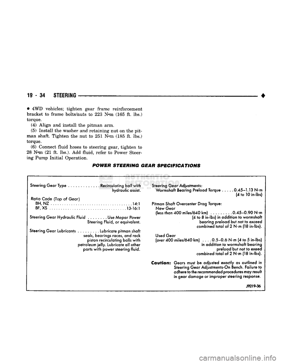
POWER STEERING GEAR SPECIFICATIONS
Steering Gear Type ............. Recirculating ball with hydraulic assist.
Ratio Code (Top
of
Gear) BH,NZ
14:1
BF,
XS 13-16:1
Steering Gear Hydraulic Fluid Use Mopar Power Steering Fluid,
or
equivalent.
Steering Gear Lubricants Lubricate pitman shaft
seals,
bearings races,
and
rack piston recirculating balls with
petroleum
jelly.
Lubricate all other parts with power steering fluid. Steering Gear Adjustments:
Wormshaft Bearing Preload Torque 0.45-1.13
Nm
(4
to
10 in-lbs)
Pitman Shaft Overcenter Drag Torque: New Gear
(less than 400 miles/640 km) ......... 0.45-0.90
Nm
(4
to 8
in-lbs)
in
addition
to
wormshaft bearing preload but not to exceed
combined total
of
2
Nm
(18 in-lbs).
Used Gear
(over 400 miles/640 km) 0.5-0.6
Nm
(4 to
5
in-lbs) in addition
to
wormshaft bearing preload but not to exeed
combined total
of
2 N-m (18 in-lbs).
Caution:
Gears must
be
adjusted exactly
as
outlined
in
Steering Gear Adjustments-On Bench. Failure
to
adhere
to
the recommended procedures may result
in gear damage
or
improper steering response.
J9219-36
Page 1024 of 1502
NV4500
TRANSMISSION OVERHAUL
21 - 23
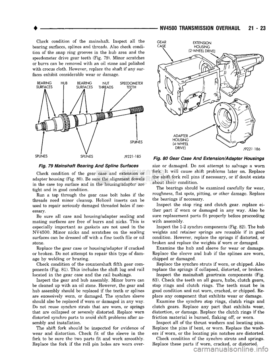
Check condition of the mainshaft. Inspect all the
bearing surfaces, splines and threads. Also check condi tion of the snap ring grooves in the hub area and the speedometer drive gear teeth (Fig. 79). Minor scratches
or burrs can be removed with an oil stone and polished
with crocus cloth. However, replace the shaft if any sur faces exhibit considerable wear or damage.
GEAR
CASE
BEARING
SURFACES HUB
BEARING
NUT
SURFACES THREADS SPEEDOMETER
TEETH
SPLINES SPLINES SPLINES
J922M85
Fig.
79 Mainshaft Bearing And
Spline
Surfaces
Check condition of the gear case and extension or
adapter housing (Fig. 80). Be sure the alignment dowels
in the case top surface and in the housing/adapter are
tight and in good condition.
Run a tap through the gear case bolt holes if the
threads need minor cleanup. Helicoil inserts can be used to repair seriously damaged threaded holes if nec
essary.
Be sure all case and housing/adapter sealing and
mating surfaces are free of burrs and nicks. This is especially important as gaskets are not used in the
NV4500. Minor nicks and scratches on the sealing surfaces can be dressed off with a fine tooth file or oil
stone.
Replace the gear case or housing/adapter if cracked
or broken. Do not attempt to repair this type of dam age by welding or brazing.
Check condition of the countershaft fifth gear com
ponents (Fig. 81). This includes the shift lug and rail located in the gear case and the rail bushings.
Inspect the gear and hub assembly. Minor burrs can
be cleaned up with an oil stone. However, the gear and hub assembly should be replaced if the teeth or splines are excessively worn, or damaged. The synchro sleeve
should also be replaced if worn or damaged in any way.
Do not reuse synchro struts that are worn, or springs
that are collapsed or severely distorted. Replace worn distorted synchro parts to avoid shift problems after as
sembly and installation.
The shift fork should be inspected for evidence of
wear and distortion. Check fit of the sleeve in the
fork to be sure the two parts fit and work smoothly.
Replace the fork if the roll pin holes are worn over-
EXTENSION
HOUSING
(2-WHEEL
DRIVE)
ADAPTER
HOUSING
(4-WHEEL
DRIVE)
J9221-186
Fig.
80 Gear
Case
And Extension/Adapter
Housings
size or damaged. Do not attempt to salvage a worn
fork. It will cause shift problems later on. Replace
the shift fork roll pins if necessary, or if doubt exists about their condition.
The bearings should be examined carefully for wear,
roughness, flat spots, pitting, or other damage. Replace
the bearings if necessary.
Inspect the stop ring and clutch gear, replace ei
ther part if worn or damaged in any way. Also be sure replacement parts fit properly before proceeding
with assembly.
Inspect the 1-2 synchro components (Fig. 82). The hub
weights and retainer springs are reusable if in good condition. However, replace the springs if distorted, or
broken and replace the weights if worn or damaged. Examine the hub and sleeve for wear or damage.
Replace the sleeve and hub if the splines are worn,
chipped or damaged. Replace the synchro struts if worn, or chipped. Also
replace the springs if collapsed, distorted, or broken. Inspect the mainshaft geartrain components (Fig.
83).
Check the teeth on all gears, hubs, clutch gears,
stop rings and clutch rings. The teeth must be in
good condition and not worn, cracked, or chipped. Re
place any component that exhibits wear or damage. Examine the synchro stop rings, clutch rings and
clutch gears. Replace any part that exhibits wear,
distortion, or damage. Replace the clutch rings if the
friction material is burned, flaking off, or worn. Inspect all of the thrust washers and locating pins.
Replace the pins if bent, or worn. Replace the wash ers if worn, or the locating pin notches are distorted. Check condition of the synchro struts and springs.
Replace these parts if worn, cracked, or distorted.
Page 1087 of 1502
21 - 86
AUTOMATIC
TRANSMISSION-32RH/36RH/37RH/42RH/46RH
•
(6)
Remove dipstick and check fluid
level
as fol
lows:
(a) Dipstick has three fluid level indicating
marks which are a MIN dot mark, an OK mark and a MAX fill arrow mark:
(b) Correct level is to MAX arrow nark on dip
stick. This is correct maximum hot fluid level. Ac
ceptable level is between OK mark and max arrow
mark on dipstick.
(c) If level is at, or below MIN level dot on dip
stick, add only enough fluid to restore correct level.
Mopar ATF Plus, type 7176 is the preferred fluid.
Mopar Dexron II can be used if ATF Plus is not
readily available.
CAUTION:
Do not
overfill
the
transmission.
Overfill
ing
may
cause
leakage out the
pump
vent which
can
be mistaken for a
pump
seal
leak. In addition,
overfilling
will
also
cause
fluid
aeration
and
foam
ing
as the
excess
fluid is picked up and churned by
the
gear
train.
This
will
significantly
reduce fluid
life.
(7) Check and note fluid condition as follows: (a) Fluid should be dark to light red in color and
free of particles and sludge.
(b) If fluid is orange, brown, or smells slightly
burned, flow test and reverse flush cooler and lines. Then change fluid and filter and road test again to
confirm proper operation.
(c) If fluid is black, dark brown, turned to sludge,
contains extensive amount of metal or friction ma
terial particles, transmission will need overhaul. Main and auxiliary coolers will have to be flow
tested and reverse flushed as well.
Effects
Of Incorrect Fluid Level A low fluid level allows the pump to take in air
along with the fluid. Air in the fluid will cause fluid
pressures to be low and develop slower than normal.
If the transmission is overfilled, the gears churn
the fluid into foam, aerating the fluid and causing
the same conditions that occur with a low level.
In either case, air bubbles cause fluid overheating,
oxidation and varnish buildup which interferes with
valve, clutch and servo operation. Foaming also causes fluid expansion which can result in fluid over
flow from the transmission vent or fill tube. Fluid
overflow can easily be mistaken for a leak if inspec
tion is not careful.
FLUID
CONTAMINATION
Transmission fluid contamination is generally a re
sult of:
• adding incorrect fluid
• failure to clean dipstick and fill tube when check ing level
• engine coolant entering the fluid • internal failure that generates debris
• overheat that generates sludge (fluid breakdown)
• failure to reverse flush cooler and lines after re
pair
• failure to replace contaminated converter after re
pair
The use of non recommended fluids can result in
transmission failure. The usual results are erratic
shifts,
slippage, abnormal wear and eventual failure
due to fluid breakdown and sludge formation. Avoid
this condition by using recommended fluids only.
The dipstick cap and fill tube should be wiped
clean before checking fluid level. Dirt, grease and
other foreign material on the cap and tube could fall
into the tube if not removed beforehand. Take the
time to wipe the cap and tube clean before withdraw ing the dipstick.
Engine coolant in the transmission fluid is gener
ally caused by a cooler malfunction. The only remedy
is to replace the radiator as the cooler in the radiator
is not a serviceable part. If coolant has circulated
through the transmission for some time, an overhaul may also be necessary; especially if shift problems
had developed.
The transmission cooler and lines should be reverse
flushed whenever a malfunction generates sludge and/or debris. The torque converter should also be re
placed at the same time.
Failure to flush the cooler and lines will result in
re-contamination and a shop comeback. Flushing ap
plies to auxiliary coolers as well. The torque con verter should also be replaced whenever a failure
generates sludge and debris. This is necessary be
cause normal converter flushing procedures will not
remove al of the contaminants.
OVERDRIVE
FOURTH
GEAR
ELECTRICAL
CONTROLS
The electrical controls governing the shift into
fourth gear consist of the control switch on the in strument panel and the overdrive solenoid on the
valve body. The control switch is in circuit with the solenoid and must be in the On position to energize
the solenoid. The transmission must also have
reached third gear range before the shift to fourth gear will occur. The control switch, valve body solenoid, case con
nectors and related wiring can all be tested with a 12
volt test lamp or a multimeter. Check continuity of each component when diagnosis indicates this is nec
essary. Switch and solejioid continuity should be checked
whenever the transmission fails to shift into fourth
gear range.
THROTTLE
VALVE
CABLE
Throttle valve cable adjustment is important to
proper operation. This adjustment positions the
Page 1090 of 1502
•
AUTOMATIC
TRANSMISSION—32RH/36RH/37RH/42RH/46RH
21 - 89
Fig.
5
Pressure
Test Port
Locations—42RH/46RH
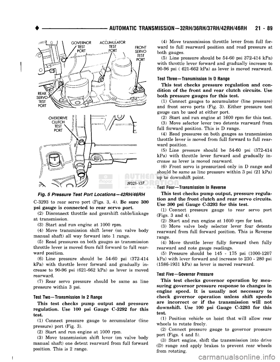
C-3293 to rear servo port (Figs. 3, 4). Be sure 300
psi gauge is connected to rear servo port.
(2) Disconnect throttle and gearshift cable/linkage
at transmission. (3) Start and run engine at 1000 rpm.
(4) Move transmission shift lever (on valve body
manual shaft) all way forward into 1 range.
(5) Read pressures on both gauges as transmission
throttle lever is moved from full forward to full rear
ward position.
(6) Line pressure should be 54-60 psi (372-414
kPa) with throttle lever forward and gradually in
crease to 90-96 psi (621-662 kPa) as lever is moved
rearward.
(7) Rear servo pressure should be same as line
pressure within 3 psi.
Test
Two—Transmission
In 2
Range
This test checks pump output and pressure
regulation. Use 100 psi Gauge C-3292 for this test. (1) Connect pressure gauge to accumulator (line
pressure) port (Fig. 3).
(2) Start and run engine at 1000 rpm.
(3) Move transmission shift lever (on valve body
manual shaft) one detent rearward from full forward
position. This is 2 range. (4) Move transmission throttle lever from full for
ward to full rearward position and read pressure at
both gauges.
(5) Line pressure should be 54-60 psi 372-414 kPa)
with throttle lever forward and gradually increase to 90-96 psi ( 621-662 kPa) as lever is moved rearward.
Test
Three—Transmission
In D
Range
This test checks pressure regulation and con
dition of the front and rear clutch circuits. Use
both pressure gauges for this test.
(1) Connect gauges to accumulator (line pressure)
and front servo ports (Fig. 3). Either pressure test
gauge can be used at either port.
(2) Start and run engine at 1600 rpm for this test.
(3) Move selector lever two detents rearward from
full forward position. This is D range.
(4) Read pressures on both gauges as transmission
throttle lever is moved from full forward to full rear
ward position.
(5) Line pressure should be 54-60 psi (372-414
kPa) with throttle lever forward and gradually in crease as lever is moved rearward. (6) Front servo is pressurized only in D range and
should be same as line pressure within 3 psi (21 kPa)
up to downshift point.
Test
Four—Transmission
In
Reverse
This test checks pump output, pressure regula
tion and the front clutch and rear servo circuits.
Use 300 psi Gauge C-3293 for this test.
(1) Connect pressure gauge to rear servo port
(Figs.
3 and 4). (2) Start and run engine at 1600 rpm for test. (3) Move valve body selector lever four detents
rearward from full forward position. This is Reverse
range.
(4) Move throttle lever fully forward then fully
rearward and note gauge readings.
(5) Pressure should be 145 - 175 psi (1000-1207
kPa) with lever forward and increase to 230 - 280 psi (1586-1931 kPa) as lever is moved rearward.
Test
Five—Governor
Pressure
This test checks governor operation by mea
suring governor pressure response to changes in
engine speed. It is usually not necessary to check governor operation unless shift speeds
are incorrect or if the transmission will not
downshift. Use 100 psi Gauge C-3293 for this
test.
(1) Position vehicle on hoist that will allow rear
wheels to rotate freely.
(2) Connect pressure gauge to governor pressure
port (Figs. 4 and 5). (3) Start engine, shift the transmission into drive
(D) range and apply brakes to prevent rear wheels
from rotating.
Page 1105 of 1502
21 - 104
AUTOMATIC
TRANSMISSION—32RH/36RH/37RH/42RH/46RH
•
Condition
POMIOSO
Ccwse
Correction
NO
START
IN
PARK
OR
NEUTRAL
1.
Gearshift
linkage
out
of
adjustment
2.
Neutral
switch
wire
broken
or
open
3.
Faulty
neutral
switch
4.
Valve
body
manual
lever
assembly
bent,
worn,
broken,
or not
aligned
with
switch
1.
Adjust linkage
2.
Check continuity
with
test lamp; repair as required
3.
Refer to service section for test and replacement procedure
4.
inspect lever
assembly
and replace if damaged
SLUGGISH
ACCELERATION
AT
LOW
SPEEDS
OR
REQUIRES
EXCESSIVE
THROTTLE
OPENING
TO MAINTAIN
HIGHWAY
SPEEDS
1.
Poor
engine
performance
2.
Gearshift
or
throttle
linkage
out of adjustment
3.
Transmission
clutches slipping
4.
Overrunning clutch in converter not holding
5. Converter overrunning clutch stuck
1.
Check engine and repair as required
2. Adjust linkage
3. Perform stall test and repair as required
4.
Perform stall test and replace converter if clutch
has
failed
5. Replace converter
FLUID
CONTAMINATED
(DISCOLORED,
FULL
OF
SLUDGE
AND/OR
METAL
AND
FRICTION
MATERIAL
PARTICULAR)
1.
If contamination occurred shortly
after
overhaul,
fluid cooler and
lines
were
not
flushed
and flow rested. This is especially
true
when original overhaul
was
to correct a problem
that
generated a large
amount of debris,
such
as a gear
failure
or a clutch
pack
failure
Note: Flushing the cooler and lines is mandatory
after
a
failure
of the converter lockup clutch
2.
Incorrect fluid used in transmission
3. Main cooler in radiator is cracked, allowing engine coolant to
enter
transmission
4.
Severe overload results in overheat, fluid break
down,
and accelerated wear, especially in high
ambient temperatures.
Most
frequent
causes
are:
• Vehicle is not properly equipped for heavy duty
service
• Tow vehicle and boat or
trailer
are both overloaded
•
Trailer
or boat are too large for tow vehicle (load exceeds rated capacity of tow vehicle)
1.
If contamination is severe, cooler flushing,
converter replacement, and another overhaul may be
necessary;
particularly so if shift
problems
were
also
present
2.
If
transmission
is operating properly, drain fluid, reverse flush cooler and lines, and change fluid
and
filter.
However, if shift problem has
developed, converter replacement and
transmission
overhaul may be required
3.
Replace radiator (and cooler) and flush lines. If problem was
diagnosed
early
enough,
fluid and
filter
change
may
only
be
necessary.
If
contamination perioa was prolonged, overhaul
and
converter replacement may be required
4.
Repair
transmission,
flush cooler, and lines.
Replace
converter if
necessary.
Install auxiliary
cooler if needed.
Also
install HD cooling system if needed. If tow vehicle and unit being towed
are both overloaded, the only repair is to reduce
the load to
rated
limits. However, if
trailer
or boat is too large for tow vehicle, the only option
is
for the owner to move up to properly-
equipped and load-rated tow vehicle
J9121-449
TRANSMISSION DIAGNOSIS