1993 DODGE TRUCK ESP
[x] Cancel search: ESPPage 365 of 1502

8D
- 14
IGNITION SYSTEMS
• (5) Test the MAP sensor ground circuit at sensor
connector terminal-A (Fig. 19) and PCM connector
terminal-4. Repair the wire harness if necessary.
(6) Test the MAP sensor ground circuit at the
PCM connector between terminal-4 and terminal-11
with an ohmmeter. If the ohmmeter indicates an
open circuit, inspect for a defective sensor ground
connection. Refer to Group 8W, Wiring for location of
this connection. If the ground connection is good, re
place the PCM. If terminal-4 has a short circuit to 12 volts +, correct this condition before replacing the
PCM.
POWERTRAIN
CONTROL MODULE {PCM)
The PCM (formerly called the SBEC or engine -con
troller) is located in the engine compartment (Fig.
20). DATA UNK CONTROL
CONNECTOR MODULE
J9314-164
Fig.
20 PCM Location The ignition system is controlled by the PCM.
For removal and installation of this component, re
fer to the Component Removal/Installation section of
this group.
For diagnostics, refer to the appropriate Powertrain
Diagnostic Procedures service manual for operation
of the DRB II scan tool.
SPARK
PLUGS
For spark plug removal, cleaning, gap adjustment
and installation, refer to the Component Removal/In
stallation section of this group. Spark plug cable boot heat shields are pressed into
the cylinder head to surround each cable boot and
spark plug (Fig. 21). These shields protect the spark
plug boots from damage (due to intense engine heat
generated by the exhaust manifolds) and should not
be removed. After the spark plug cable has been in stalled, the lip of the cable boot should have a small
air gap to the top of the heat shield (Fig. 21). Faulty carbon and/or gas fouled plugs generally
cause hard starting, but they will clean up at higher
engine speeds. Faulty plugs can be identified in a
Fig.
21 Heat
Shields
number of ways: poor fuel economy, power loss, de
crease in engine speed, hard starting and, in general,
poor engine performance.
Remove the spark plugs and examine them for
burned electrodes and fouled, cracked or broken por celain insulators. Keep plugs arranged in the order
in which they were removed from the engine. An iso
lated plug displaying an abnormal condition indi
cates that a problem exists in the corresponding
cylinder. Replace spark plugs at the intervals recom
mended in the maintenance chart in Group 0, Lubri
cation and Maintenance.
Spark plugs that have low mileage may be cleaned
and reused if not otherwise defective. Refer to the
following Spark Plug Condition section of this group.
CONDITION
NORMAL OPERATING
The few deposits present on the spark plug will
probably be light tan or slightly gray in color. This is evident with most grades of commercial gasoline (Fig. 22). There will not be evidence of electrode
burning. Gap growth will not average more than ap proximately 0.025 mm (.001 in) per 1600 km (1000
miles) of operation. Spark plugs that have normal
wear can usually be cleaned, have the electrodes filed, have the gap set and then be installed.
Some fuel refiners in several areas of the United
States have introduced a manganese additive (MMT)
for unleaded fuel. During combustion, fuel with
MMT causes the entire tip of the spark plug to be coated with a rust colored deposit. This rust color can
be misdiagnosed as being caused by coolant in the combustion chamber. Spark plug performance is not affected by MMT deposits.
COLD
FOULING/CARBON FOULING
Cold fouling is sometimes referred to as carbon
fouling. The deposits that cause cold fouling are ba-
Page 368 of 1502
•
IGNITION SYSTEMS
80-17
or punctured, there will
be a
noticeable spark jump
from
the
damaged area
to the
test probe.
The
cable
running from
the
ignition coil
to the
distributor
cap
can
be
checked
in the
same manner. Cracked, dam aged
or
faulty cables should
be
replaced with resis
tance type cable. This
can be
identified
by the
words ELECTRONIC SUPPRESSION printed
on the
cable
jacket.
Use
an
ohmmeter
to
test
for
open circuits, exces
sive resistance
or
loose terminals. Remove
the
dis
tributor
cap
from
the
distributor.
Do not
remove cables from
cap.
Remove cable from spark plug.
Connect ohmmeter
to
spark plug terminal
end of ca
ble
and to
corresponding electrode
in
distributor
cap.
Resistance should
be 250 to 1000
Ohms
per
inch
of
cable.
If not,
remove cable from distributor
cap
tower and connect ohmmeter
to the
terminal ends
of
cable.
If resistance
is not
within specifications
as
found
in
the Spark Plug Cable Resistance chart, replace
the
cable. Test
all
spark plug cables
in
this manner.
SPARK
PLUG CABLE RESISTANCE
MINIMUM
MAXIMUM
250
Ohms
Per
Inch
1000
Ohms
Per
Inch
3000
Ohms
Per
Foot
12,000
Ohms
Per
Foot
J908D-43 To test ignition coil-to-distributor
cap
cable,
do not
remove
the
cable from
the cap.
Connect ohmmeter
to
rotor button (center contact)
of
distributor
cap and
terminal
at
ignition coil
end of
cable.
If
resistance
is
not within specifications
as
found
in the
Spark Plug
Cable Resistance chart, remove
the
cable from
the
distributor
cap.
Connect
the
ohmmeter
to the
termi
nal ends
of the
cable.
If
resistance
is not
within spec
ifications
as
found
in the
Spark Plug Cable
Resistance chart, replace
the
cable. Inspect
the
igni
tion coil tower
for
cracks, burns
or
corrosion.
For removal
and
installation
of
spark plug cables,
refer
to
Spark Plug Secondary Cables
in the
Compo nent Removal/Installation section.
THROTTLE POSITION
SENSOR
TEST
To perform
a
complete test
of
this sensor
and its
circuitry, refer
to the DRB II
diagnostic scan tool.
Also refer
to the
appropriate Powertrain Diagnostics
Procedures manual.
To
test
the
sensor only, refer
to
the following: The throttle position sensor
can be
tested with
a
digital voltmeter.
The
center terminal
of the
sensor
connector
is the
output terminal
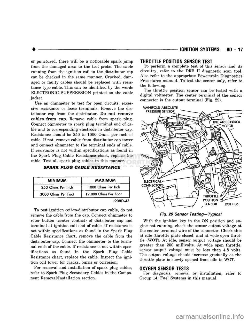
(Fig. 29).
MANIFOLD ABSOLUTE
Fig.
29
Sensor
Testing—Typical With
the
ignition
key in the ON
position
and en
gine
not
running, check
the
sensor output voltage
at
the center terminal wire
of the
connector. Check this at idle (throttle plate closed)
and at
wide open throt
tle (WOT).
At
idle, sensor output voltage should
be
greater than
200
millivolts.
At
wide open throttle, sensor output voltage must
be
less than
4,8
volts.
The output voltage should increase gradually
as the
throttle plate
is
slowly opened from idle
to WOT.
OXYGEN
SENSOR
TESTS
For diagnosis, removal
or
installation, refer
to
Group
14,
Fuel Systems
in
this manual.
Page 407 of 1502
8F - 4
AUDIO SYSTEMS
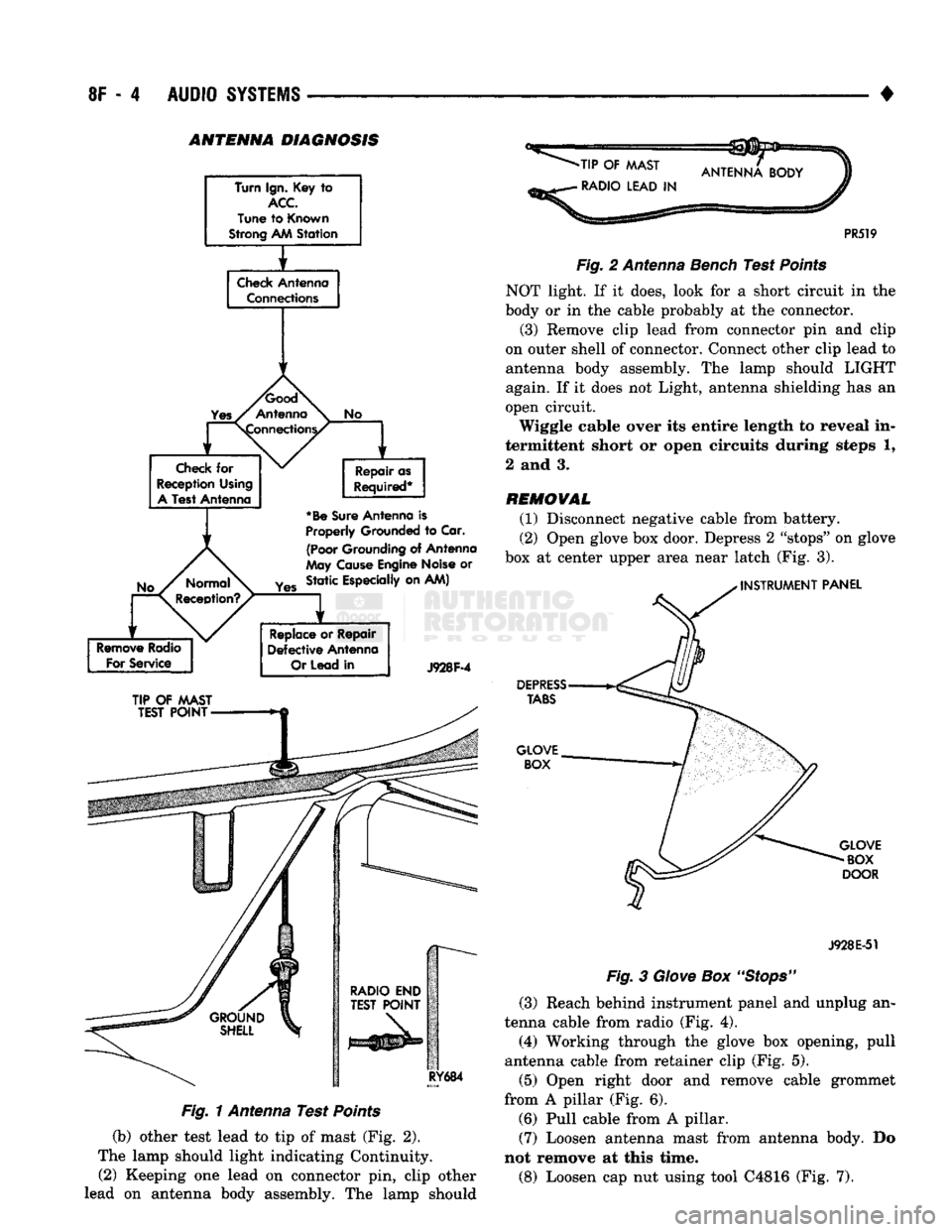
• ANTENNA DIAGNOSIS
Turn Ign. Key
to
ACC
Tune
to
Known
Strong AM
Station
f
Check
Antenna Connections
1
1
No
Check
for
Reception Using
A
Test Antenna Repair as
Required*
*Be
Sure
Antenna
is
Properly
Grounded
to
Car.
(Poor
Grounding
of
Antenna
May
Cause
Engine Noise
or
Yes
Static Especially on AM)
Remove
Radio
For
Service
Replace
or
Repair
Defective
Antenna
Or
Lead
in
J928F-4
TIP
OF
MAST
TEST
POINT
RY684
Fig. 1 Antenna Test Points
(b) other test lead to tip of mast (Fig. 2).
The lamp should light indicating Continuity. (2) Keeping one lead on connector pin, clip other
lead on antenna body assembly. The lamp should
-TIP
OF
MAST
•
RADIO LEAD
IN
PR519
Fig.
2 Antenna Bench Test
Points
NOT light. If it does, look for a short circuit in the
body or in the cable probably at the connector.
(3) Remove clip lead from connector pin and clip
on outer shell of connector. Connect other clip lead to
antenna body assembly. The lamp should LIGHT
again. If it does not Light, antenna shielding has an
open circuit.
Wiggle cable over its entire length to reveal in
termittent short or open circuits during steps 1,
2 and 3.
REMOVAL
(1) Disconnect negative cable from battery.
(2) Open glove box door. Depress 2 "stops" on glove
box at center upper area near latch (Fig. 3).
INSTRUMENT
PANEL
DEPRESS
TABS
GLOVE BOX
GLOVE
BOX
DOOR
J928E-51
Fig.
3
Glove
Box
"Stops"
(3) Reach behind instrument panel and unplug an
tenna cable from radio (Fig. 4).
(4) Working through the glove box opening, pull
antenna cable from retainer clip (Fig. 5).
(5) Open right door and remove cable grommet
from A pillar (Fig. 6). (6) Pull cable from A pillar. (7) Loosen antenna mast from antenna body. Do
not remove at this time.
(8) Loosen cap nut using tool C4816 (Fig. 7).
Page 417 of 1502
8H - 2
VEHICLE SPEED CONTROL SYSTEM
• TO RESUME: After disengaging the speed control
system by tapping the brake or clutch pedal, push
the RESUME/ACCEL button to return vehicle to the
previously set speed. TO ACCELERATE: While speed control is en
gaged, hold the RESUME/ACCEL button depressed and release at a new desired speed. This will allow
the vehicle to continuously accelerate and set at a
higher speed setting.
TAP-UP: When the speed control system is en
gaged, tapping the RESUME/ACCEL button will in
crease the speed setting by 2 mph (3 km/h). The system will respond to multiple tap-ups.
TO ACCELERATE for PASSING: Depress the
accelerator as you would normally. When the pedal
is released the vehicle will return to the speed set
ting in memory.
SERVO
CONNECTOR
J918H-20
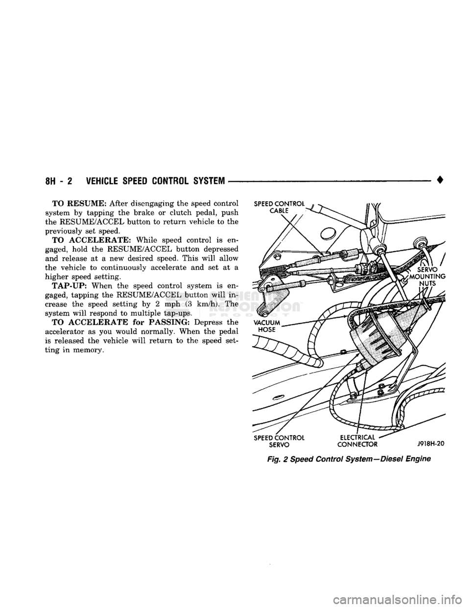
Fig.
2
Speed
Control
System
—Diesel
Engine
Page 616 of 1502
•
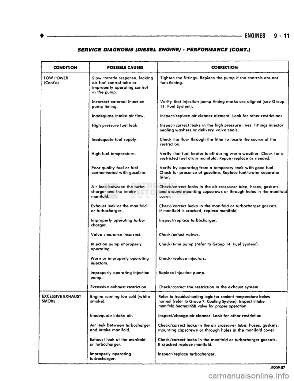
ENGINES
9 - 11 SERVICE DIAGNOSIS (DIESEL ENGINE) - PERFORMANCE (CONT.)
CONDITION
POSSIBLE
CAUSES
CORRECTION
LOW
POWER
(Cont'd)
SJow
throttle
response, leaking
air
fuel
control
tube
or
improperly
operating
control
in the pump. Tighten the fittings. Replace the pump if the controls are not
functioning.
Incorrect
external
injection
pump
timing. Verify
that
injection pump timing marks are aligned (see Group
14, Fuel System).
Inadequate intake air flow. Inspect/replace air cleaner element. Look for other restrictions.
High
pressure
fuel
leak. Inspect/correct leaks in the high pressure lines, fittings
injector
sealing
washers or delivery valve
seals.
Inadequate
fuel
supply.
Check
the flow through the
filter
to locate the source of the
restriction.
High
fuel
temperature. Verify
that
fuel
heater is off during warm weather. Check for a
restricted
fuel
drain manifold. Repair/replace as needed.
Poor
quality
fuel
or
fuel
contaminated
with
gasoline. Verify by operating from a temporary tank
with
good
fuel.
Check
for presence of
gasoline.
Replace
fuel/water
separator
filter.
Air
leak between the turbo- charger and the intake manifold. Check/correct leaks in the air crossover tube,
hoses,
gaskets,
and
around mounting capscrews or through holes in the manifold
cover.
Exhaust
leak at the manifold
or turbocharger. Check/correct leaks in the manifold or turbocharger
gaskets.
If manifold is cracked, replace manifold.
Improperly operating turbo-
charger. Inspect/replace turbocharger.
Valve clearance incorrect.
Check/adjust
valves.
Injection pump improperly
operating. Check/time pump
(refer
to Group 14, Fuel System).
Worn
or improperly operating injectors. Check/replace injectors.
Improperly operating injection
pump.
Replace
injection pump.
Excessive
exhaust restriction. Check/correct the restriction in the exhaust system.
EXCESSIVE
EXHAUST
SMOKE
Engine
running too cold
(white
smoke).
Refer to troubleshooting logic for coolant
temperature
below
normal
(refer
to Group 7,
Cooling
System).
Inspect intake
manifold heater/KSB valve for proper operation.
Inadequate intake air.
Inspect/change
air cleaner. Look for other restriction.
Air
leak between turbocharger
and
intake manifold. Check/correct leaks in the air crossover tube,
hoses,
gaskets,
mounting capscrews or through holes in the manifold cover.
Exhaust
leak at the manifold
or turbocharger. Check/correct leaks in the manifold or turbocharger
gaskets.
If cracked replace manifold.
Improperly operating
turbocharger. Inspect/replace turbocharger.
J9209-57
Page 632 of 1502
•
3.9L
ENGINE
9 - 27 (2) If valves or seats are reground, check valve
stem height. If valve is too long, replace cylinder
head.
(3) Install new seals on all valve guides. Install
valve springs and valve retainers.
(4) Compress valve springs with Valve Spring
Compressor Tool MD-998772A, install locks and re
lease tool. If valves and/or seats are ground, measure
the installed height of springs. Make sure the mea surement is taken from bottom of spring seat in cyl
inder head to the bottom surface of spring retainer. If
spacers are installed, measure from the top of spacer.
If height is greater than 42.86 mm (1-11/16 inches), install a 1.587 mm (1/16 inch) spacer in head coun-
terbore. This should bring spring height back to nor
mal 41.27 to 42.86 mm (1-5/8 to
1-11/16
inch).
VALVE STEM SEAL
/
SPRING REPLACEMENT
This procedure is done with the cylinder head in
stalled. (1) Set engine basic timing to TDC and remove air
cleaner. (2) Remove cylinder head covers and spark plugs.
(3) Remove coil wire from distributor and secure to
good ground to prevent engine from starting. (4) Using suitable socket and flex handle at crank
shaft retaining bolt, turn engine so the No.l piston is
at Top Dead Center on the compression stroke. (5) Remove rocker arms.
(6) With air hose attached to an adapter installed
in No.l spark plug hole, apply 620-689 kPa (90-100
psi) air pressure. (7) Using Valve Spring Compressor Tool
MD-998772A, compress valve spring and remove re
tainer valve locks and valve spring. (8) Install seals on the exhaust valve stem and po
sition down against valve guides. (9) The intake valve stem seals should be pushed
firmly and squarely over the valve guide using the valve stem as a guide. DO NOT force seal against
top of guide. When installing the valve retainer
locks,
compress the spring only enough to install the
locks.
(10) Follow the same procedure on the remaining 5
cylinders using the firing sequence
1-6-5-4-3-2.
Make sure piston in cylinder is at TDC on the valve spring
that is being removed. (11) Remove adapter from the No.l spark plug
hole.
(12) Install rocker arms.
(13) Install covers and coil wire to distributor.
(14) Install air cleaner.
(15) Road test vehicle.
HYDRAULIC
TAPPETS
Before disassembling any part of the engine to cor
rect tappet noise, check the oil pressure. If vehicle
has no oil pressure gauge, install a reliable gauge at the pressure sending unit. The pressure should be be
tween 207-552 kPa (30-80 psi) at 3,000 RPM.
Check the oil level after the engine reaches normal
operating temperature. Allow 5 minutes to stabilize
oil level, check dipstick.
The oil level in the pan should never be above the
FULL mark or below the ADD OIL mark on dipstick.
Either of these 2 conditions could be responsible for
noisy tappets.
OIL
LEWEL
HIGH
If oil level is above the FULL mark, it is possible
for the connecting rods to dip into the oil. With the engine running, this condition could create foam in
the oil pan. Foam in oil pan would be fed to the hy draulic tappets by the oil pump causing them to lose
length and allow valves to seat noisily.
LOW
Low oil level may allow oil pump to take in air.
When air is fed to the tappets, they lose length
which allows valves to seat noisily. Any leaks on in
take side of oil pump through which air can be drawn will create the same tappet action. Check the
lubrication system from the intake strainer to the
pump cover, including the relief valve retainer cap.
When tappet noise is due to aeration, it may be in
termittent or constant, and usually more than 1 tap
pet will be noisy. When oil level and leaks have been corrected, operate the engine at fast idle. Run engine
for a sufficient time to allow all of the air inside the
tappets to be bled out.
TAPPET
NOISE DIAGNOSIS
(1) To determine source of tappet noise, operate en
gine at idle with cylinder head covers removed. (2) Feel each valve spring or rocker arm to detect
noisy tappet. The noisy tappet will cause the affected
spring and/or rocker arm to vibrate or feel rough in
operation.
Worn valve guides or cocked springs are some
times mistaken for noisy tappets. If such is the
case, noise may be dampened by applying side
thrust on the valve spring. If noise is not appre ciably reduced, it can be assumed the noise is in
the tappet. Inspect the rocker arm push rod sockets and push rod ends for wear.
(3) Valve tappet noise ranges from light noise to a
heavy click. A light noise is usually caused by exces sive leak down around the unit plunger or by the
plunger partially sticking in the tappet body cylin der. The tappet should be replaced. A heavy click is
caused by a tappet check valve not seating or by for
eign particles becoming wedged between the plunger
and the tappet body. This will cause the plunger to
stick in the down position. This heavy click will be
Page 635 of 1502
i - 30
3.9L
ENGINE
J9209-130
Fig.
4
Measuring
Timing
Chain
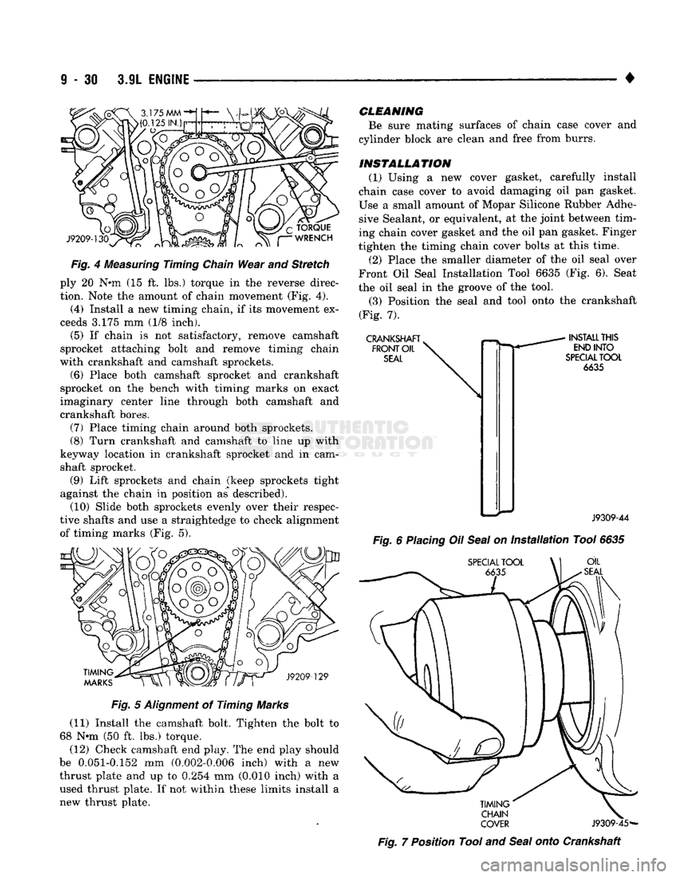
Wear and Stretch ply 20 N*m (15 ft. lbs.) torque in the reverse direc
tion. Note the amount of chain movement (Fig. 4).
(4) Install a new timing chain, if its movement ex
ceeds 3.175 mm (1/8 inch).
(5) If chain is not satisfactory, remove camshaft
sprocket attaching bolt and remove timing chain
with crankshaft and camshaft sprockets. (6) Place both camshaft sprocket and crankshaft
sprocket on the bench with timing marks on exact
imaginary center line through both camshaft and
crankshaft bores.
(7) Place timing chain around both sprockets. (8) Turn crankshaft and camshaft to line up with
keyway location in crankshaft sprocket and in cam
shaft sprocket.
(9) Lift sprockets and chain (keep sprockets tight
against the chain in position as described). (10) Slide both sprockets evenly over their respec
tive shafts and use a straightedge to check alignment of timing marks (Fig. 5).
TIMING
MARKS
J9209-129
Fig.
5
Alignment
of Timing Marks
(11) Install the camshaft bolt. Tighten the bolt to
68 Nnn (50 ft. lbs.) torque. (12) Check camshaft end play. The end play should
be 0.051-0.152 mm (0.002-0.006 inch) with a new
thrust plate and up to 0.254 mm (0.010 inch) with a used thrust plate. If not within these limits install a
new thrust plate.
CLEANING
Be sure mating surfaces of chain case cover and
cylinder block are clean and free from burrs.
INSTALLATION
(1) Using a new cover gasket, carefully install
chain case cover to avoid damaging oil pan gasket.
Use a small amount of Mopar Silicone Rubber Adhe
sive Sealant, or equivalent, at the joint between tim ing chain cover gasket and the oil pan gasket. Finger
tighten the timing chain cover bolts at this time.
(2) Place the smaller diameter of the oil seal over
Front Oil Seal Installation Tool 6635 (Fig. 6). Seat
the oil seal in the groove of the tool.
(3) Position the seal and tool onto the crankshaft
(Fig. 7).
CRANKSHAFT
>
FRONT
OIL
SEAL
INSTALL
THIS
END
INTO
SPECIAL
TOOL
6635
J9309-44
Fig.
6
Placing
Oil
Seal
on
Installation
Tool
6635
SPECIAL
TOOL
\\ OIL
SEAL
TIMING'
CHAIN
COVER
J9309-45-
Fig.
7 Position Tool and
Seal
onto Crankshaft
Page 637 of 1502
9
- 32 3.9L
ENGINE
•
Fig,
10 timing
Chain
Oil Tab installation
Fig,
11 Camshaft Bearings Removal and Installation
with
Tool
C-3132-A
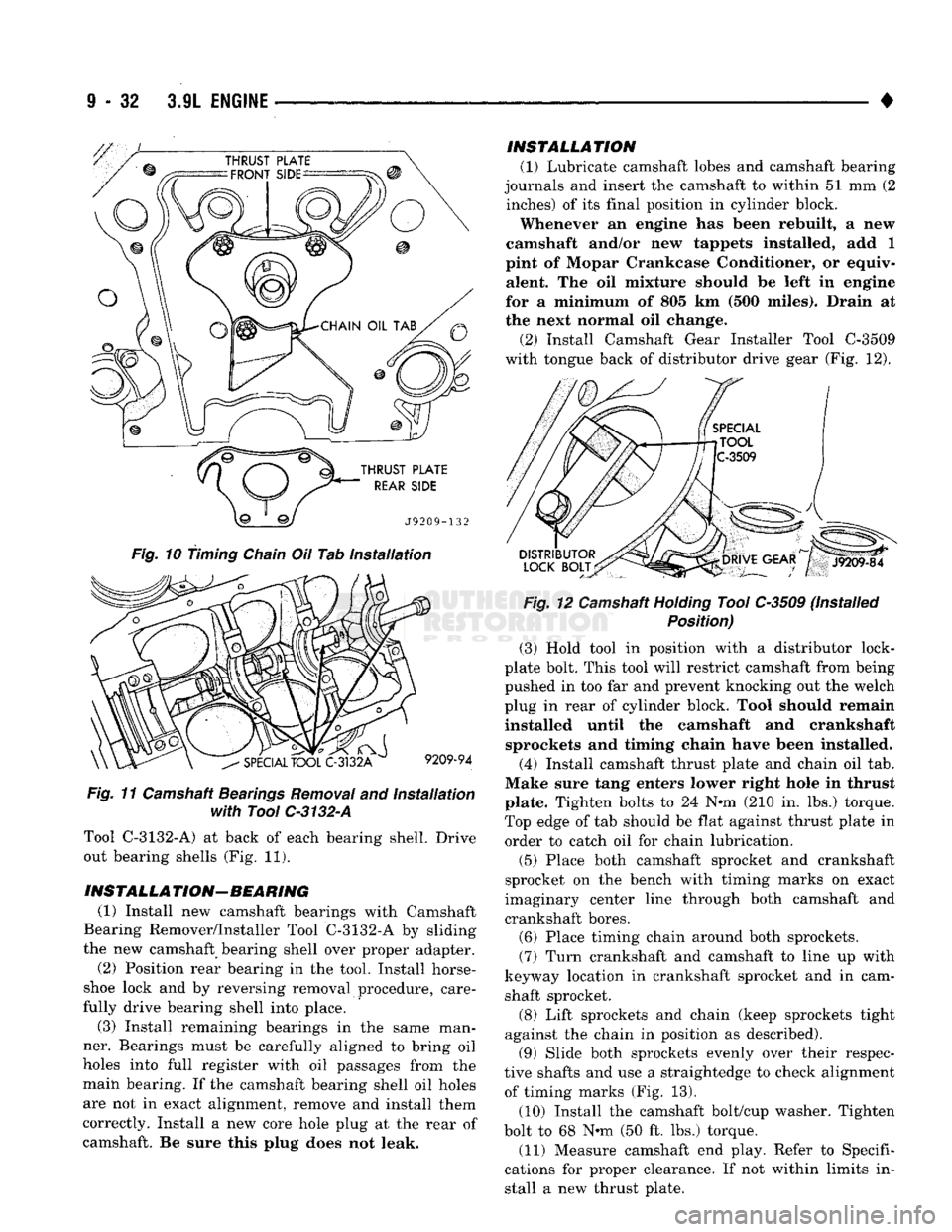
Tool C-3132-A) at back of each bearing shell. Drive out bearing shells (Fig. 11).
INSTALLA
TION— BEARING (1) Install new camshaft bearings with Camshaft
Bearing Remover/Installer Tool C-3132-A by sliding
the new camshaft bearing shell over proper adapter.
(2) Position rear bearing in the tool. Install horse
shoe lock and by reversing removal procedure, care
fully drive bearing shell into place.
(3) Install remaining bearings in the same man
ner. Bearings must be carefully aligned to bring oil
holes into full register with oil passages from the main bearing. If the camshaft bearing shell oil holes
are not in exact alignment, remove and install them
correctly. Install a new core hole plug at the rear of
camshaft. Be sure this plug does not leak. INSTALLATION
(1) Lubricate camshaft lobes and camshaft bearing
journals and insert the camshaft to within 51 mm (2 inches) of its final position in cylinder block.
Whenever an engine has been rebuilt, a new
camshaft and/or new tappets installed, add 1
pint of Mopar Crankcase Conditioner, or equiv alent. The oil mixture should be left in engine
for a minimum of 805 km (500 miles). Drain at
the next normal oil change.
(2) Install Camshaft Gear Installer Tool C-3509
with tongue back of distributor drive gear (Fig. 12).
Fig.
12 Camshaft
Holding
Tool C-3509 (Installed
Position)
(3) Hold tool in position with a distributor lock-
plate bolt. This tool will restrict camshaft from being
pushed in too far and prevent knocking out the welch
plug in rear of cylinder block. Tool should remain
installed until the camshaft and crankshaft sprockets and timing chain have been installed.
(4) Install camshaft thrust plate and chain oil tab.
Make sure tang enters lower right hole in thrust plate. Tighten bolts to 24 N*m (210 in. lbs.) torque.
Top edge of tab should be flat against thrust plate in order to catch oil for chain lubrication.
(5) Place both camshaft sprocket and crankshaft
sprocket on the bench with timing marks on exact
imaginary center line through both camshaft and
crankshaft bores.
(6) Place timing chain around both sprockets.
(7)
Turn crankshaft and camshaft to line up with
keyway location in crankshaft sprocket and in cam shaft sprocket.
(8) Lift sprockets and chain (keep sprockets tight
against the chain in position as described).
(9) Slide both sprockets evenly over their respec
tive shafts and use a straightedge to check alignment of timing marks (Fig. 13).
(10) Install the camshaft bolt/cup washer. Tighten
bolt to 68 N*m (50 ft. lbs.) torque.
(11) Measure camshaft end play. Refer to Specifi
cations for proper clearance. If not within limits in stall a new thrust plate.