1993 DODGE TRUCK ESP
[x] Cancel search: ESPPage 729 of 1502
9
- 124 5.9L
(DIESEL)
ENGINE
Fig.
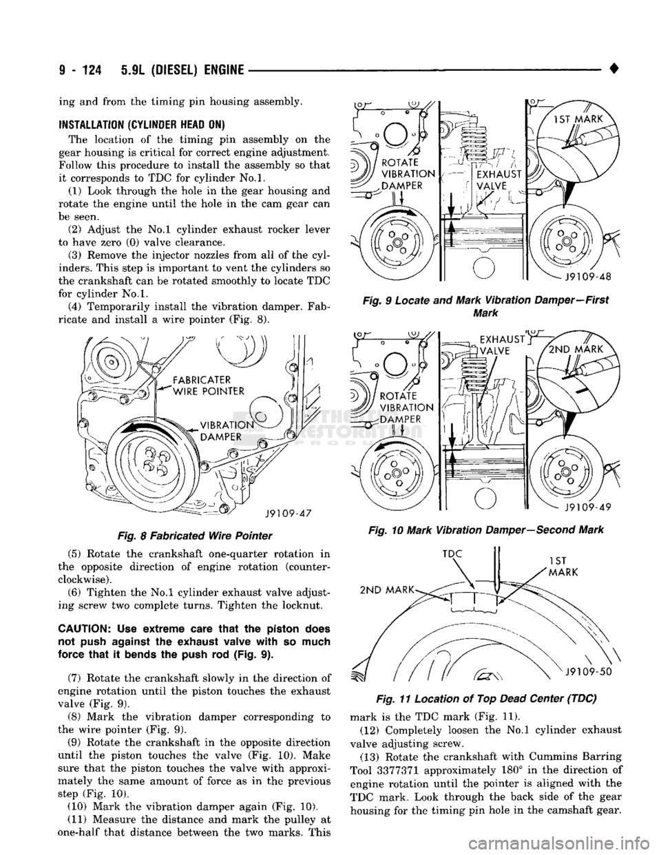
8 Fabricated Wire Pointer (5) Rotate the crankshaft one-quarter rotation in
the opposite direction of engine rotation (counter clockwise).
(6) Tighten the No.l cylinder exhaust valve adjust
ing screw two complete turns. Tighten the locknut.
CAUTION; Use extreme
care
that
the
piston
does
not
push
against
the
exhaust
valve with so
much
force that it
bends
the
push
rod (Fig. 9).
(7) Rotate the crankshaft slowly in the direction of
engine rotation until the piston touches the exhaust
valve (Fig. 9). (8) Mark the vibration damper corresponding to
the wire pointer (Fig. 9).
(9) Rotate the crankshaft in the opposite direction
until the piston touches the valve (Fig. 10). Make sure that the piston touches the valve with approxi
mately the same amount of force as in the previous step (Fig. 10).
(10) Mark the vibration damper again (Fig. 10). (11) Measure the distance and mark the pulley at
one-half that distance between the two marks. This •
Fig.
9 Locate and Mark
Vibration
Damper—First
Mark
Fig.
10 Mark
Vibration
Damper—Second
Mark
Fig.
11 Location of Top
Dead
Center (TDC) mark is the TDC mark (Fig. 11).
(12) Completely loosen the No.l cylinder exhaust
valve adjusting screw. (13) Rotate the crankshaft with Cummins Barring
Tool 3377371 approximately 180° in the direction of engine rotation until the pointer is aligned with the
TDC mark. Look through the back side of the gear housing for the timing pin hole in the camshaft gear.
ing and from the timing pin housing assembly.
INSTALLATION
(CYLINDER
HEAD
ON) The location of the timing pin assembly on the
gear housing is critical for correct engine adjustment.
Follow this procedure to install the assembly so that it corresponds to TDC for cylinder No.l. (1) Look through the hole in the gear housing and
rotate the engine until the hole in the cam gear can
be seen. (2) Adjust the No.l cylinder exhaust rocker lever
to have zero (0) valve clearance.
(3) Remove the injector nozzles from all of the cyl
inders. This step is important to vent the cylinders so
the crankshaft can be rotated smoothly to locate TDC
for cylinder No.l.
(4) Temporarily install the vibration damper. Fab
ricate and install a wire pointer (Fig. 8).
Page 730 of 1502
•
5JL
(DIESEL) ENGINE
9 - 125 (14) Reset the valves on No.l cylinder and install
valve cover.
(15) Install timing pin housing assembly and a
new gasket.
(16) Apply a coat of Loctite 59241 Liquid Teflon, or
equivalent to the threads of the Torx head bolts. (17) Hold the timing pin in the hole to align the
housing and install the Torx head bolts. Tighten the
Torx bolts to 5 N»m (44 in. lbs.) torque.
(18) Install the injectors and bleed the fuel system
(refer to Group 14, Fuel System).
INSTALLATION
(CYLINDER
HEAD
OFF) The timing pin assembly is precisely located on the
gear housing to correspond to TDC for Cylinder No.l.
The timing pin assembly must be relocated if the gear housing is interchanged.
(1) Temporarily install the vibration damper and a
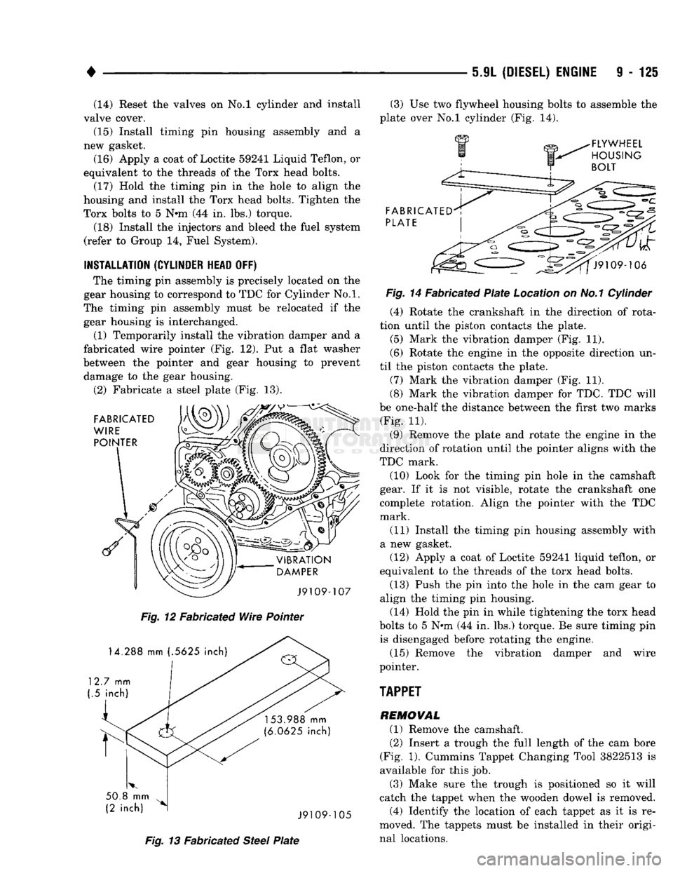
fabricated wire pointer (Fig. 12). Put a flat washer
between the pointer and gear housing to prevent damage to the gear housing.
(2) Fabricate a steel plate (Fig. 13).
Fig.
12 Fabricated
Wire
Pointer
Fig.
13 Fabricated
Steel
Plate
(3) Use two flywheel housing bolts to assemble the
plate over No.l cylinder (Fig. 14).
Fig.
14 Fabricated
Plate
Location on No.1 Cylinder (4) Rotate the crankshaft in the direction of rota
tion until the piston contacts the plate.
(5) Mark the vibration damper (Fig. 11).
(6) Rotate the engine in the opposite direction un
til the piston contacts the plate. (7) Mark the vibration damper (Fig. 11).
(8) Mark the vibration damper for TDC. TDC will
be one-half the distance between the first two marks (Fig. 11).
(9) Remove the plate and rotate the engine in the
direction of rotation until the pointer aligns with the
TDC mark. (10) Look for the timing pin hole in the camshaft
gear. If it is not visible, rotate the crankshaft one
complete rotation. Align the pointer with the TDC
mark.
(11) Install the timing pin housing assembly with
a new gasket. (12) Apply a coat of Loctite 59241 liquid teflon, or
equivalent to the threads of the torx head bolts.
(13) Push the pin into the hole in the cam gear to
align the timing pin housing.
(14) Hold the pin in while tightening the torx head
bolts to 5 Nnn (44 in. lbs.) torque. Be sure timing pin is disengaged before rotating the engine.
(15) Remove the vibration damper and wire
pointer.
TAPPET
REMOVAL (1) Remove the camshaft. (2) Insert a trough the full length of the cam bore
(Fig. 1). Cummins Tappet Changing Tool 3822513 is
available for this job.
(3) Make sure the trough is positioned so it will
catch the tappet when the wooden dowel is removed. (4) Identify the location of each tappet as it is re
moved. The tappets must be installed in their origi
nal locations.
Page 812 of 1502
FRAME
AND
BUMPERS
13 - 25
FUNCTION
The frame is the foundation and the structural cen
ter of the vehicle. The primary function of a frame is
to provide support and attachment locations: • For all the chassis/drivetrain components
• For the cab/body
• For the vehicle payload While limiting deflections and twisting of the
frame members. The frame maintains the correct relationship and
alignment of the powertrain. This relationship and
alignment ensures normal operation of the attached
units.
CONSTRUCTION MATERIAL High-strength, carbon steel with a minimum yield
strength of 32,000 psi is used to construct frame side
rails.
A frame made of 32,000 psi minimum yield
strength steel has, in reality, a range of 32,000 to
44,000 psi yield strength.
For 4WD vehicle applications, the frame side rails
reinforcements are constructed of the same high- strength, carbon steel as the side rails.
BENDING RESISTANCE A frame reacts to its load and the road surface de
viations by deflecting and twisting. The primary de
flecting frame members are the side rails. Resistance
to frame twist is provided by the crossmembers.
FRAME
INSPECTION/MEASUREMENTS
INSPECTION Inspect the frame members for visible damage and
metal deformations. Inspect all riveted, bolted and
welded connections for looseness and/or missing hardware. All damaged areas must be repaired and/or the
frame members replaced, as necessary.
MEASUREMENTS Measure the frame for mis-alignment with the cab/
body and cargo box attached to the frame. Figures 7, 8, 9 provide the frame alignment reference dimen
sions.
The following information applies to all measure
ments.
(1) Place the vehicle on a level surface.
(2) If the vehicle is loaded, verify the vehicle does
not exceed the gross vehicle weight rating (GVWR).
Verify the load is distributed in the vehicle as evenly as possible. For better measurement results, remove
the cargo/payload from the vehicle.
(3) Measure the tire inflation pressures. Adjust as
necessary.
HORIZONTAL/DIAGONAL
FRAME MEASUREMENTS
Determine the frame horizontal, according to the
following procedure.
(1) Select several reference points along one frame
side rail, preferably at the crossmember junctions.
(2) Transfer these reference points to the surface/
floor. Paper sheets can be attached to the surface be low the reference points.
(3) Locate the same reference points on the other
frame side rail. Transfer them to the surface/floor.
(4) Move the vehicle away. Measure between all
the reference points diagonally from and parallel to
the side rails (Fig. 10). The corresponding measure ments should not differ by more than 6 mm (1/4 in).
(5)
Measure the distance between the two front
reference points. Measure the distance between the
two rear reference points. Divide each distance in
half and indicate the two half-way points on the sur
face/floor. Designate the front point as 1 and the rear
point as 2 (Fig. 10).
(6) Place a chalk-line between points 1 and 2 (Fig.
10) and snap the string.
(7) Determine how close the center line is to the
diagonal intersection points in Figure 10.
(8) The marks on the floor will show the amount of
frame misalignment.
(9) The reference point transferred from one side
rail should be within 3 mm (1/8 in) of the opposite
reference point.
(10) Frame bow to the side should not exceed 3
mm per 2540 mm (1/8 inch per 100 inches) in frame
length.
(11) The overall width of the frame should not
vary more than 3 mm (1/8 in). (12) Repeat steps (1) through (11) after straighten
ing the frame.
Refer to Figures 7, 8, and 9 for frame horizon
tal alignment reference dimensions.
TWIST
AND PARALLEL FRAME MEASUREMENTS
Determine the amount of frame twist using the fol
lowing procedure.
(1) Mark the vertical reference points under the
frame side rails at 305-mm (12-in) intervals. Start at
the rear frame crossmember.
(2) Measure the distance up from a level surface/
floor to each corresponding reference point. (3) The distance to a reference point under one
side rail should be a maximum of 3 mm (1/8 in)
dif
ference than the opposite side rail.
Refer to Figures 7, 8 and 9 for frame vertical
alignment reference dimensions.
Page 821 of 1502
14
- 2
FUEL SYSTEM
•
GASOLINE/OXYGENATE
BLENDS
Some fuel suppliers blend unleaded gasoline with
materials that contain oxygen such as alcohol, MTBE and ETBE. The type and amount of oxygenate used
in the blend is important. The following are gener
ally used in gasoline blends:
ETHANOL
Ethanol (Ethyl or Grain Alcohol) properly blended,
is used as a mixture of 10 percent ethanol and 90
percent gasoline. Gasoline with ethanol may be
used in your vehicle.
METHANOL
CAUTION:
DO NOT USE
GASOLINES CONTAINING
METHANOL.
Use of methanol/gasoline blends may re
sult in starting and driveability problems. In addition,
damage may be done to critical fuel system compo
nents.
Methanol (Methyl or Wood Alcohol) is used in a va
riety of concentrations blended with unleaded gaso
line.
You may encounter fuels containing 3 percent
or more methanol along with other alcohols called co-
solvents.
Problems that are the result of using methanol/gas
oline blends are not the responsibility of Chrysler Corporation. They may not be covered by the vehicle
warranty.
MTBE/ETBE
Gasoline and MTBE (Methyl Tertiary Butyl Ether)
blends are a mixture of unleaded gasoline and up to 15 percent
MTBE.
Gasoline and
ETBE
(Ethyl
Ter
tiary Butyl Ether) are blends of gasoline and up to 17 percent ETBE. Gasoline blended with MTBE or
ETBE may be used in your vehicle.
CLEAN
AIR GASOLINE Many gasolines are now being blended that con
tribute to cleaner air, especially in those areas of the
country where air pollution levels are high. These
new blends provide a cleaner burning fuel and some are referred to as Reformulated Gasoline.
In areas of the country where carbon monoxide lev
els are high, gasolines are being treated with oxy
genated materials such as MTBE, ETBE and ethanol.
Chrysler Corporation supports these efforts toward
cleaner air and recommends that you use these gas
olines as they become available.
FUEL
REQUIREMENTS-DIESEL ENGINE
Use good quality diesel fuel from a reputable sup
plier in your Chrysler Corporation vehicle. For most
year-round service, number 2 (two) diesel fuel meet ing ASTM specification D-975 will provide good per
formance. If the vehicle is exposed to extreme cold (below -18°C - 0°F), or for any reason is required to
operate at colder than normal conditions for pro longed periods, then dilution of the 2D fuel with 50
percent kerosine or number ID diesel fuel will pro
vide better protection from fuel gelling or wax-plug ging of the fuel filters. Diesel fuel is seldom
completely free of water. To prevent fuel system
trouble, including fuel tube (line) freezing in winter, drain the accumulated water using the drain pro
vided. If you buy good quality fuel and follow the cold weather advice above, fuel conditioners should
not be required in your vehicle.
Page 842 of 1502
•
FUEL SYSTEM
14 - 23
USED
WITH
7-INCH
RAIL TIGHTENING TORQUE
A
30 FT
LBS
(41 N-m)
B
TIGHTEN
TO
SECURE TANK
C
100 IN
LBS
(11 N-m)
REAR
STRAP
VIEW
IN
CIRCLE
Z (30 GAL
TANK)
PRESSURE
RELIEF/
ROLLOVER
VALVE
LOCKNUT Fig.
4 Mid-Frame Mounted
Fuel
Tank Removal/Installation—Typical
PUMP/GAUGE
SENDING
UNIT
ELECTRICAL
CONNECTOR FUEL
SUPPLY
TUBE
FUEL
RETURN TUBE
J9114-232
J9014-183
NUT
(2)
ASSEMBLY
(200
INCH-POUNDS)
Fig.
5
Fuel Pump
Module Connections—Typical
FUEL
RESERVOIR
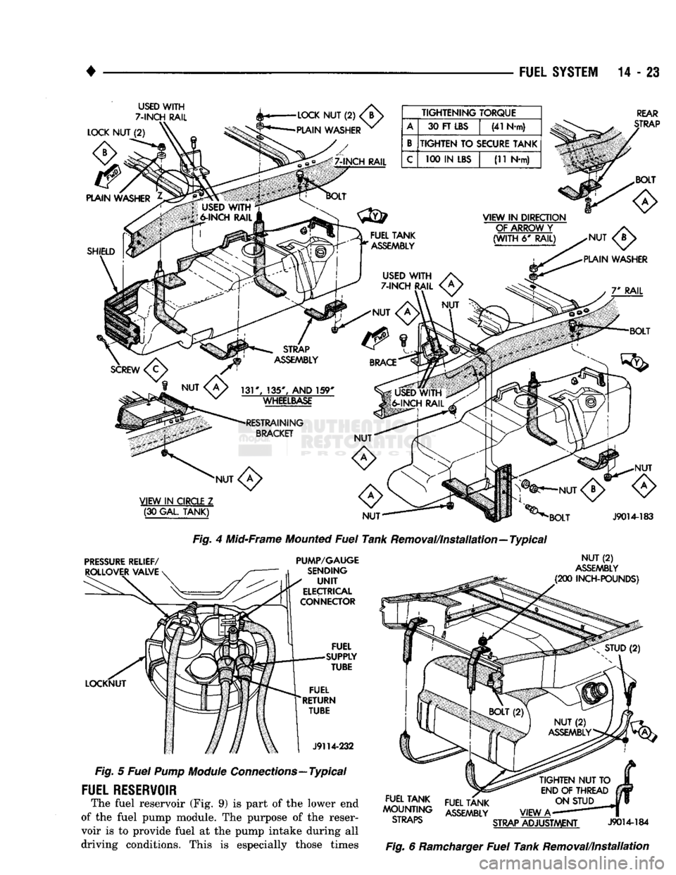
The fuel reservoir (Fig. 9) is part of the lower end
of the fuel pump module. The purpose of the reser
voir is to provide fuel at the pump intake during all
driving conditions. This is especially those times
TIGHTEN
NUT TO
END
OF
THREAD ON STUD
VIEW
A-
STRAP
ADJUSTMENT
J9014-184
Fig.
6 Ramcharger
Fuel
Tank Removal/Installation
FUEL TANK
^OUNTWG ASSEMBLY
ol
KAP5>
Page 851 of 1502
14
- 32
FUEL SYSTEM
•
BATTERY VOLTAGE—PCM
INPUT
The battery voltage input provides power
to the
powertrain control module (PCM).
It
also informs
the
PCM what voltage level
is
supplied
to the
ignition
coil
and
fuel injectors. If battery voltage
is low, the PCM
will increase injec
tor pulse width (period
of
time that
the
injector
is
ener
gized).
This
is
done
to
compensate
for the
reduced flow
through injector caused
by the
lowered voltage.
BRAKE
SWITCH-PCM
INPUT
When
the
brake light switch
is
activated,
the
pow
ertrain control module
(PCM)
receives
an
input indi
cating that
the
brakes
are
being applied. After
receiving this input,
the PCM
maintains idle speed
to
a
scheduled
rpm
through control
of the
idle
air
control
(IAC)
motor.
The
brake switch input
is
also
used
to
operate
the
speed control system.
CAMSHAFT POSITION SENSOR—PCM
INPUT
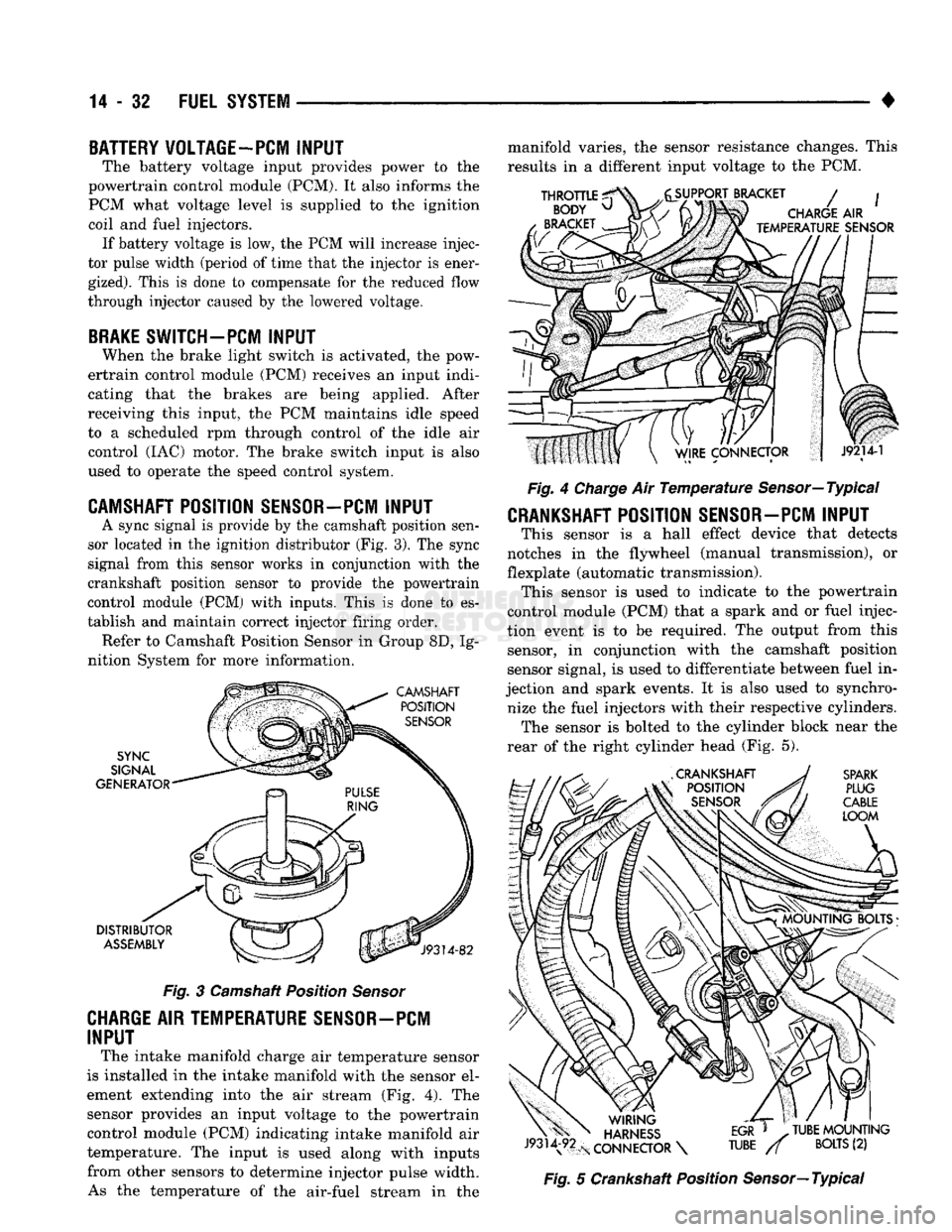
A sync signal
is
provide
by the
camshaft position sen
sor located
in the
ignition distributor
(Fig.
3).
The
sync
signal from this sensor works
in
conjunction with
the
crankshaft position sensor
to
provide
the
powertrain
control module
(PCM)
with inputs. This
is
done
to es
tablish
and
maintain correct injector firing order. Refer
to
Camshaft Position Sensor
in
Group
8D, Ig
nition System
for
more information.
Fig.
3
Camshaft Position
Sensor
CHARGE AIR TEMPERATURE SENSOR-PCM
INPUT
The intake manifold charge
air
temperature sensor
is installed
in the
intake manifold with
the
sensor
el
ement extending into
the air
stream
(Fig. 4). The
sensor provides
an
input voltage
to the
powertrain control module
(PCM)
indicating intake manifold
air
temperature.
The
input
is
used along with inputs from other sensors
to
determine injector pulse width. As
the
temperature
of the
air-fuel stream
in the
manifold varies,
the
sensor resistance changes. This
results
in a
different input voltage
to the PCM.
Fig.
4
Charge
Air
Temperature
Sensor—Typical
CRANKSHAFT POSITION SENSOR-PCM INPUT
This sensor
is a
hall effect device that detects
notches
in the
flywheel (manual transmission),
or
flexplate (automatic transmission). This sensor
is
used
to
indicate
to the
powertrain
control module
(PCM)
that
a
spark
and or
fuel injec
tion event
is to be
required.
The
output from this sensor,
in
conjunction with
the
camshaft position
sensor signal,
is
used
to
differentiate between fuel
in
jection
and
spark events.
It is
also used
to
synchro nize
the
fuel injectors with their respective cylinders. The sensor
is
bolted
to the
cylinder block near
the
rear
of the
right cylinder head
(Fig. 5).
Fig.
5
Crankshaft Position Sensor—Typical
Page 854 of 1502
•
FUEL SYSTEM
14 - 35
SENSOR
RETURN—PCM
INPUT
Sensor Return provides a low noise ground refer
ence for all system sensors.
THROTTLE POSITION
SENSOR
(TPS)-PCM
INPUT
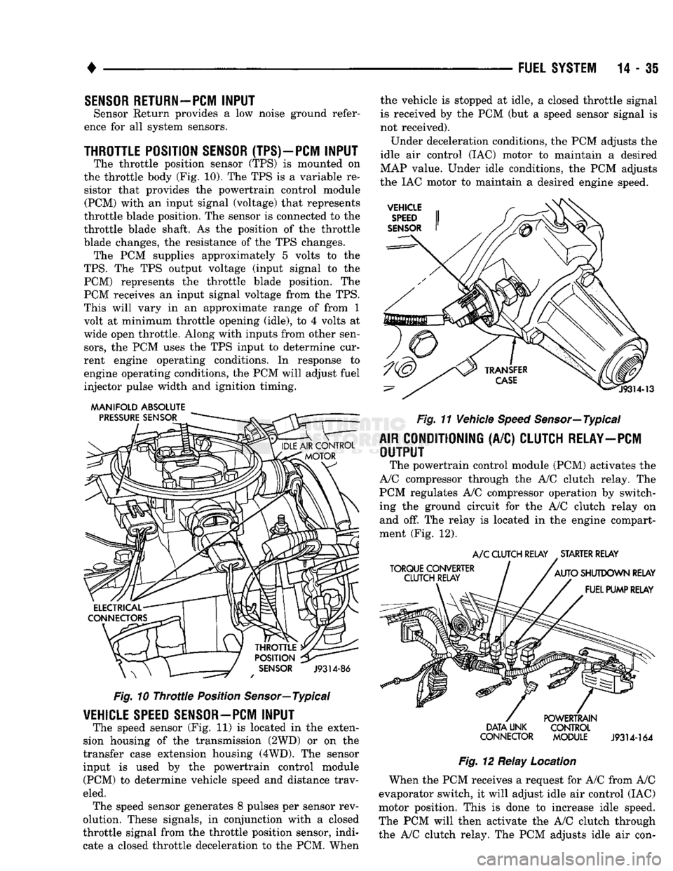
The throttle position sensor (TPS) is mounted on
the throttle body (Fig. 10). The TPS is a variable re sistor that provides the powertrain control module (PCM) with an input signal (voltage) that represents
throttle blade position. The sensor is connected to the
throttle blade shaft. As the position of the throttle
blade changes, the resistance of the TPS changes. The PCM supplies approximately 5 volts to the
TPS.
The TPS output voltage (input signal to the PCM) represents the throttle blade position. The
PCM receives an input signal voltage from the TPS.
This will vary in an approximate range of from 1
volt at minimum throttle opening (idle), to 4 volts at
wide open throttle. Along with inputs from other sen
sors,
the PCM uses the TPS input to determine cur
rent engine operating conditions. In response to
engine operating conditions, the PCM will adjust fuel
injector pulse width and ignition timing.
MANIFOLD ABSOLUTE
Fig.
10
Throttle
Position Sensor—Typical
VEHICLE
SPEED
SENSOR—PCM
INPUT
The speed sensor (Fig. 11) is located in the exten
sion housing of the transmission (2WD) or on the
transfer case extension housing (4WD). The sensor input is used by the powertrain control module (PCM) to determine vehicle speed and distance trav
eled. The speed sensor generates 8 pulses per sensor rev
olution. These signals, in conjunction with a closed
throttle signal from the throttle position sensor, indi
cate a closed throttle deceleration to the PCM. When the vehicle is stopped at idle, a closed throttle signal
is received by the PCM (but a speed sensor signal is
not received).
Under deceleration conditions, the PCM adjusts the
idle air control (IAC) motor to maintain a desired
MAP value. Under idle conditions, the PCM adjusts
the IAC motor to maintain a desired engine speed.
Fig.
11 Vehicle
Speed
Sensor—Typical
AIR
CONDITIONING
(A/C)
CLUTCH RELAY—PCM
OUTPUT
The powertrain control module (PCM) activates the
A/C compressor through the A/C clutch relay. The
PCM regulates A/C compressor operation by switch
ing the ground circuit for the A/C clutch relay on and off. The relay is located in the engine compart
ment (Fig. 12).
A/C
CLUTCH RELAY STARTER RELAY
DATA LINK CONTROL
CONNECTOR MODULE
J9314-164
Fig.
12 Relay Location
When the PCM receives a request for A/C from A/C
evaporator switch, it will adjust idle air control (IAC)
motor position. This is done to increase idle speed.
The PCM will then activate the A/C clutch through
the A/C clutch relay. The PCM adjusts idle air con-
Page 856 of 1502
•
FUEL SYSTEM
14 - 37 used only on vehicles equipped with the 5.9L heavy
duty cycle (HDC) engine. Refer to Group 25, Emis
sion Control System for information.
EVAP CANISTER PURGE SOLENOID-PCM
OUTPUT
Refer to Group 25, Emission Control System. See
EVAP Canister Purge Solenoid.
FUEL INJECTORS-PCM
OUTPUT
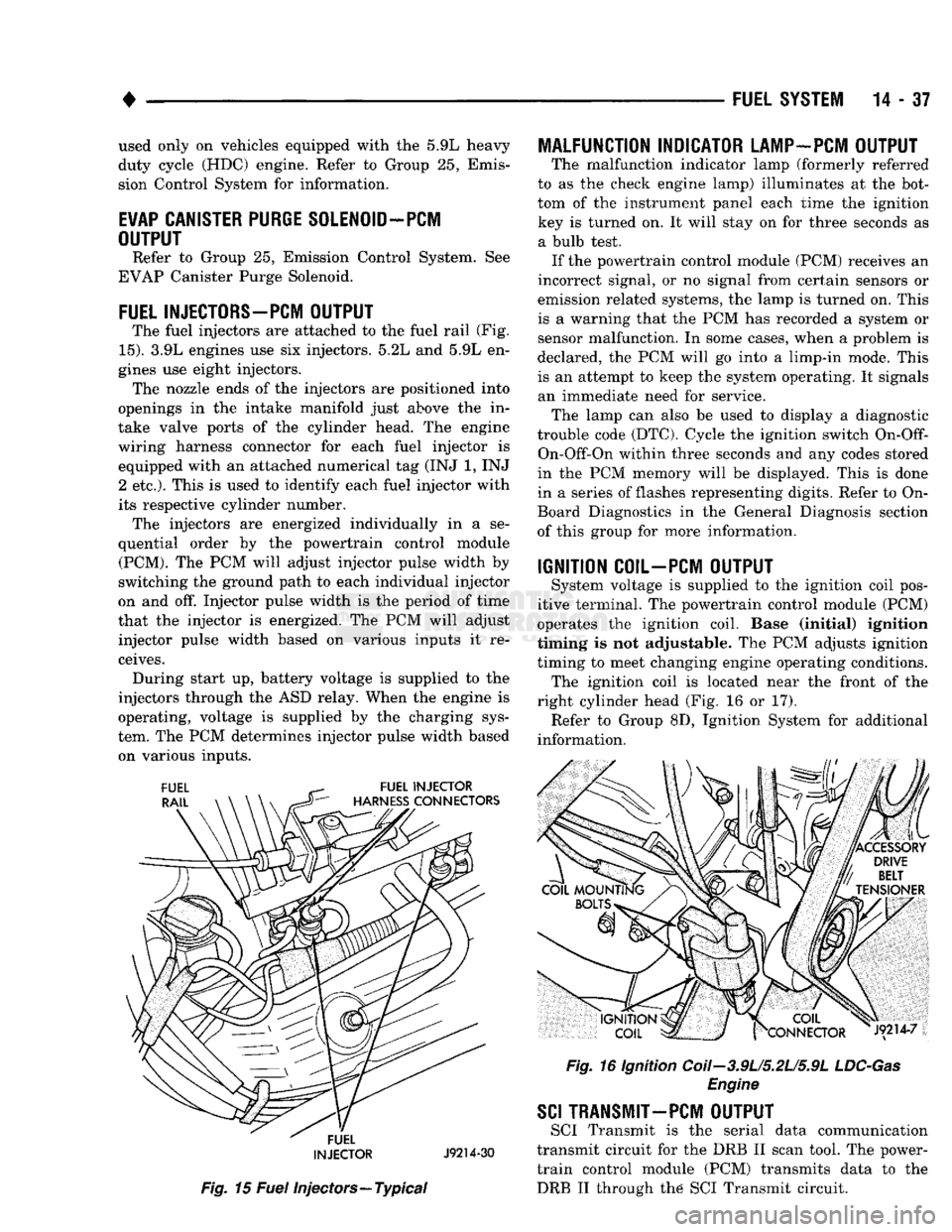
The fuel injectors are attached to the fuel rail (Fig.
15).
3.9L engines use six injectors. 5.2L and 5.9L en
gines use eight injectors. The nozzle ends of the injectors are positioned into
openings in the intake manifold just above the in
take valve ports of the cylinder head. The engine
wiring harness connector for each fuel injector is equipped with an attached numerical tag (INJ 1, INJ 2 etc.). This is used to identify each fuel injector with
its respective cylinder number. The injectors are energized individually in a se
quential order by the powertrain control module (PCM). The PCM will adjust injector pulse width by
switching the ground path to each individual injector
on and off. Injector pulse width is the period of time
that the injector is energized. The PCM will adjust injector pulse width based on various inputs it re
ceives. During start up, battery voltage is supplied to the
injectors through the ASD relay. When the engine is
operating, voltage is supplied by the charging sys
tem. The PCM determines injector pulse width based on various inputs.
FUEL
INJECTOR
J9214-30
Fig.
15
Fuel
injectors—Typical
MALFUNCTION INDICATOR LAMP-PCM OUTPUT
The malfunction indicator lamp (formerly referred
to as the check engine lamp) illuminates at the bot
tom of the instrument panel each time the ignition key is turned on. It will stay on for three seconds as a bulb test. If the powertrain control module (PCM) receives an
incorrect signal, or no signal from certain sensors or
emission related systems, the lamp is turned on. This
is a warning that the PCM has recorded a system or
sensor malfunction. In some cases, when a problem is
declared, the PCM will go into a limp-in mode. This
is an attempt to keep the system operating. It signals an immediate need for service. The lamp can also be used to display a diagnostic
trouble code (DTC). Cycle the ignition switch
On-Off-
On-Off-On within three seconds and any codes stored
in the PCM memory will be displayed. This is done
in a series of flashes representing digits. Refer to On-
Board Diagnostics in the General Diagnosis section
of this group for more information.
IGNITION COIL-PCM OUTPUT
System voltage is supplied to the ignition coil pos
itive terminal. The powertrain control module (PCM)
operates the ignition coil. Base (initial) ignition
timing is not adjustable. The PCM adjusts ignition
timing to meet changing engine operating conditions. The ignition coil is located near the front of the
right cylinder head (Fig. 16 or 17). Refer to Group 8D, Ignition System for additional
information.
Fig.
16 Ignition Coii-3.9U5.2U5.9L
LDC-Gas
Engine
SCI
TRANSMIT—PCM OUTPUT
SCI Transmit is the serial data communication
transmit circuit for the DRB II scan tool. The power- train control module (PCM) transmits data to the DRB II through the SCI Transmit circuit.