1993 DODGE TRUCK ESP
[x] Cancel search: ESPPage 857 of 1502
14 - 38
FUEL SYSTEM
•
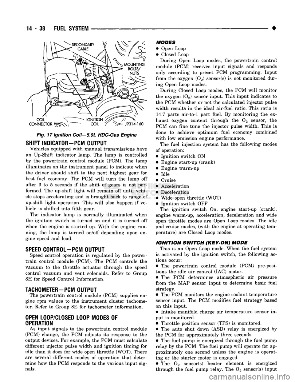
Fig.
17 Ignition Coil—5.9L
HDC-Gas
Engine
SHIFT INDICATOR-PCM
OUTPUT
Vehicles equipped with manual transmissions have
an Up-Shift indicator lamp. The lamp is controlled
by the powertrain control module (PCM). The lamp illuminates on the instrument panel to indicate when
the driver should shift to the next highest gear for
best fuel economy. The PCM will turn the lamp off after 3 to 5 seconds if the shift of gears is not per
formed. The up-shift light will remain off until vehi cle stops accelerating and is brought back to range of
up-shift light operation. This will also happen if ve
hicle is shifted into fifth gear. The indicator lamp is normally illuminated when
the ignition switch is turned on and it is turned off
when the engine is started up. With the engine run
ning, the lamp is turned on/off depending upon en
gine speed and load.
SPEED
CONTROL-PCM
OUTPUT
Speed control operation is regulated by the power-
train control module (PCM). The PCM controls the
vacuum to the throttle actuator through the speed
control vacuum and vent solenoids. Refer to Group
8H for Speed Control Information.
TACHOMETER—PCM
OUTPUT
The powertrain control module (PCM) supplies en
gine rpm values to the instrument cluster tachome ter. Refer to Group 8E for tachometer information.
OPEN
LOOP/CLOSED LOOP MODES
OF
OPERATION
As input signals to the powertrain control module
(PCM) change, the PCM adjusts its response to the
output devices. For example, the PCM must calculate
different injector pulse width and ignition timing for
idle than it does for wide open throttle (WOT). There
are several different modes of operation that deter
mine how the PCM responds to the various input sig
nals.
MODES
• Open Loop
• Closed Loop During Open Loop modes, the powertrain control
module (PCM) receives input signals and responds
only according to preset PCM programming. Input
from the oxygen (02) sensor(s) is not monitored dur
ing Open Loop modes.
During Closed Loop modes, the PCM will monitor
the oxygen (02) sensor input. This input indicates to
the PCM whether or not the calculated injector pulse width results in the ideal air-fuel ratio. This ratio is 14.7 parts air-to-1 part fuel. By monitoring the ex
haust oxygen content through the 02 sensor, the
PCM can fine tune the injector pulse width. This is done to achieve optimum fuel economy combined
with low emission engine performance.
The fuel injection system has the following modes
of operation:
• Ignition switch ON • Engine start-up (crank)
• Engine warm-up
• Idle
• Cruise • Acceleration
• Deceleration
• Wide open throttle (WOT)
• Ignition switch OFF The ignition switch On, engine start-up (crank),
engine warm-up, acceleration, deceleration and wide
open throttle modes are Open Loop modes. The idle and cruise modes, (with the engine at operating tem
perature) are Closed Loop modes.
IGNITION
SWITCH
(KEY-ON)
MODE
This is an Open Loop mode. When the fuel system
is activated by the ignition switch, the following ac
tions occur:
• The powertrain control module (PCM) pre-posi-
tions the idle air control (IAC) motor. • The PCM determines atmospheric air pressure
from the MAP sensor input to determine basic fuel strategy.
• The PCM monitors the engine coolant temperature sensor input. The PCM modifies fuel strategy based
on this input.
• Intake manifold charge air temperature sensor in
put is monitored.
• Throttle position sensor (TPS) is monitored. • The auto shut down (ASD) relay is energized by
the PCM for approximately three seconds. • The fuel pump is energized through the fuel pump
relay by the PCM. The fuel pump will operate for ap
proximately one second unless the engine is operat ing or the starter motor is engaged.
• The 02 sensor(s) heater element is energized
through the fuel pump relay. The 02 sensor(s) input
Page 859 of 1502
14
- 40
FUEL
SYSTEM
• • Park/Neutral switch (gear indicator signal—auto,
trans,
only)
• Oxygen (02) sensor(s) Based on these inputs, the following occurs:
• Voltage is applied to the fuel injectors with the
PCM. The PCM will then adjust the injector pulse
width by turning the ground circuit to each individ
ual injector on and off.
• The PCM monitors the 02 sensor(s) input and ad
justs air-fuel ratio. It also adjusts engine idle speed through the idle air control (IAC) motor.
• The PCM adjusts ignition timing by turning the
ground path to the coil on and off.
• The PCM operates the A/C compressor clutch
through the clutch relay. This happens if A/C has
been selected by the vehicle operator and requested
by the A/C thermostat.
ACCELERATION MODE
This is an Open Loop mode. The powertrain control
module (PCM) recognizes an abrupt increase in
throttle position or MAP pressure as a demand for
increased engine output and vehicle acceleration.
The PCM increases injector pulse width in response
to increased throttle opening.
DECELERATION MODE
When the engine is at operating temperature, this
is an Open Loop mode. During hard deceleration, the
powertrain control module (PCM) receives the follow ing inputs.
• Air conditioning select signal (if equipped)
• Air conditioning request signal (if equipped)
• Battery voltage
• Engine coolant temperature sensor
• Crankshaft position sensor
• Intake manifold charge air temperature sensor
• Manifold absolute pressure (MAP) sensor
• Throttle position sensor (TPS)
• Camshaft position sensor signal (in the distributor)
• Park/Neutral switch (gear indicator signal —auto,
trans,
only)
If the vehicle is under hard deceleration with the
proper rpm and closed throttle conditions, the PCM
will ignore the oxygen sensor input signal. The PCM
will enter a fuel cut-off strategy in which it will not supply battery voltage to the injectors. If a hard de
celeration does not exist, the PCM will determine the
proper injector pulse width and continue injection.
Based on the above inputs, the PCM will adjust en
gine idle speed through the idle air control (IAC) mo
tor. The PCM adjusts ignition timing by turning the
ground path to the coil on and off.
The PCM opens the ground circuit to the A/C
clutch relay to disengage the A/C compressor clutch.
This is done until the vehicle is no longer under de
celeration (if the A/C system is operating).
WIDE OPEN
THROTTLE
MODE
This is an Open Loop mode. During wide open
throttle operation, the powertrain control module (PCM) receives the following inputs.
• Battery voltage
• Crankshaft position sensor
• Engine coolant temperature sensor
• Intake manifold charge air temperature sensor
• Manifold absolute pressure (MAP) sensor
• Throttle position sensor (TPS) • Camshaft position sensor signal (in the distributor) During wide open throttle conditions, the following
occurs:
• Voltage is applied to the fuel injectors with the
powertrain control module (PCM). The PCM will
then control the injection sequence and injector pulse
width by turning the ground circuit to each individ ual injector on and off. The PCM ignores the oxygen sensor input signal and provides a predetermined amount of additional fuel. This is done by adjusting
injector pulse width.
• The PCM adjusts ignition timing by turning the
ground path to the coil on and off.
• The PCM opens the ground circuit to the A/C
clutch relay to disengage the A/C compressor clutch.
This will be done for approximately 15 seconds (if the air conditioning system is operating).
If the vehicle has a manual transmission, the up
shift light is operated by the PCM.
IGNITION
SWITCH
OFF
MODE
When ignition switch is turned to OFF position,
the PCM stops operating the injectors, ignition coil,
ASD relay and fuel pump relay.
THROTTLE
BODY
Filtered air from the air cleaner enters the intake
manifold through the throttle body (Fig. 18). Fuel does not enter the intake manifold through the throt
tle body. Fuel is sprayed into the manifold by the fuel injectors. The throttle body is mounted on the
intake manifold. It contains an air control passage (Fig. 19) controlled by an idle air control (IAC) mo
tor. The air control passage is used to supply air for idle conditions. A throttle valve (plate) is used to supply air for above idle conditions. The throttle position sensor (TPS), idle air control
(IAC) motor and manifold absolute pressure sensor
(MAP) are attached to the throttle body. The acceler
ator pedal cable, speed control cable and transmis
sion control cable (when equipped) are connected to
the throttle arm. A (factory adjusted) set screw is used to mechani
cally limit the position of the throttle body throttle
plate. Never attempt to adjust the engine idle speed using this screw. All idle speed functions are
controlled by the PCM.
Page 864 of 1502
•
FUEL
SYSTEM
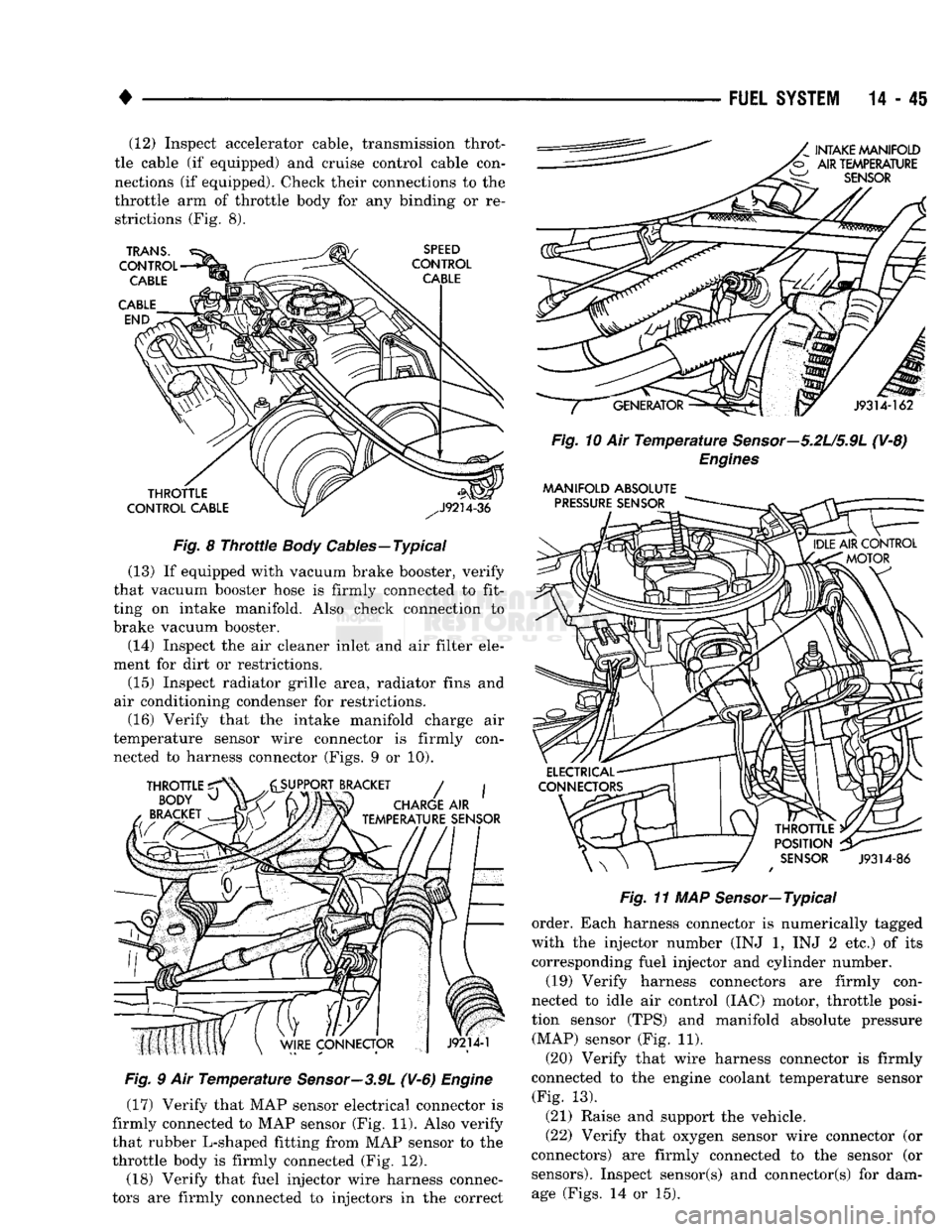
14-45 (12) Inspect accelerator cable, transmission throt
tle cable (if equipped) and cruise control cable con
nections (if equipped). Check their connections to the
throttle arm of throttle body for any binding or re strictions (Fig. 8).
Fig.
8
Throttle
Body
Cables—Typical
(13) If equipped with vacuum brake booster, verify
that vacuum booster hose is firmly connected to fit
ting on intake manifold. Also check connection to
brake vacuum booster.
(14) Inspect the air cleaner inlet and air filter ele
ment for dirt or restrictions.
(15) Inspect radiator grille area, radiator fins and
air conditioning condenser for restrictions. (16) Verify that the intake manifold charge air
temperature sensor wire connector is firmly con nected to harness connector (Figs. 9 or 10).
Fig.
9 Air
Temperature
Sensor—3.9L
(V-6)
Engine
(17) Verify that MAP sensor electrical connector is
firmly connected to MAP sensor (Fig. 11). Also verify
that rubber L-shaped fitting from MAP sensor to the
throttle body is firmly connected (Fig. 12).
(18) Verify that fuel injector wire harness connec
tors are firmly connected to injectors in the correct
Fig.
10 Air
Temperature
Sensor—5.2U5.9L
(V-8)
Engines
MANIFOLD
ABSOLUTE
Fig.
11 MAP Sensor—Typical
order. Each harness connector is numerically tagged
with the injector number (INJ 1, INJ 2 etc.) of its
corresponding fuel injector and cylinder number.
(19) Verify harness connectors are firmly con
nected to idle air control (IAC) motor, throttle posi
tion sensor (TPS) and manifold absolute pressure (MAP) sensor (Fig. 11).
(20) Verify that wire harness connector is firmly
connected to the engine coolant temperature sensor (Fig. 13).
(21) Raise and support the vehicle.
(22) Verify that oxygen sensor wire connector (or
connectors) are firmly connected to the sensor (or sensors). Inspect sensor(s) and connector(s) for damage (Figs. 14 or 15).
Page 881 of 1502
14-62 FUEL
SYSTEM
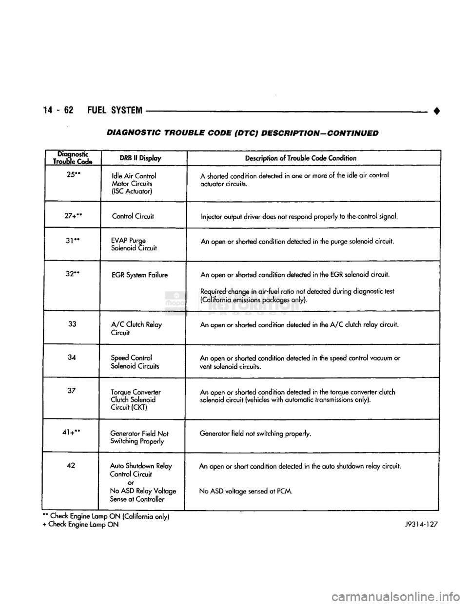
• DIAGNOSTIC TROUBLE CODE (DTC) DESCRIPTION-CONTINUED
Diagnostic
Trouble Code
DRB
If Display
Description of Trouble Code Condition
25**
Idle Air Control
Motor Circuits
(ISC
Actuator) A shorted condition detected in one or more of the idle air control
actuator circuits.
27+**
Control
Circuit
Injector output driver does not
respond
properly to the control
signal.
31**
EVAP
Purge
Solenoid Circuit An open or shorted condition detected in the purge solenoid circuit.
32**
EGR System Failure An open or shorted condition detected in the EGR solenoid circuit.
Required change in air-fuel ratio not detected during diagnostic test
(California emissions packages only).
33 A/C Clutch Relay
Circuit An open or shorted condition detected in the A/C clutch relay circuit.
34 Speed Control
Solenoid Circuits An open or shorted condition detected in the speed control vacuum or
vent solenoid circuits.
37 Torque Converter
Clutch Solenoid Circuit
(CKT)
An open or shorted condition detected in the torque converter clutch
solenoid circuit (vehicles with automatic transmissions only).
41+** Generator Field Not
Switching Properly Generator field not switching properly.
42 Auto Shutdown Relay
Control Circuit
or
No
ASD
Relay Voltage
Sense at Controller An open or short condition detected in the auto shutdown relay circuit.
No
ASD
voltage sensed at PCM.
**
Check Engine Lamp ON (California only)
+ Check Engine Lamp ON J9314-127
Page 919 of 1502
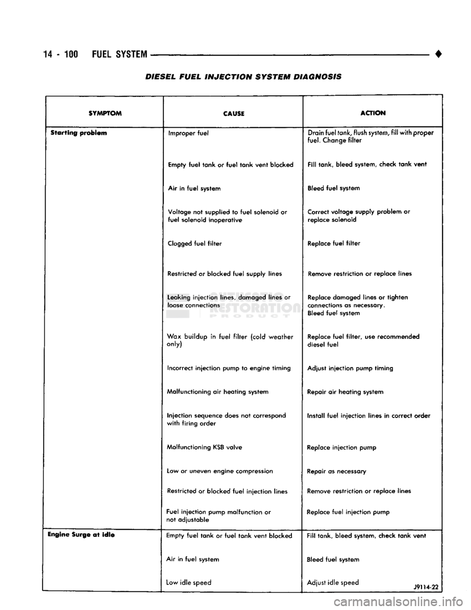
14-100
FUEL
SYSTEM
•
DIESEL
FUEL
INJECTION
SYSTEM DIAGNOSIS
SYMPTOM CAUSE
ACTION
Starting problem Improper
fuel
Drain
fuel
tank,
flush
system,
fill
with
proper
fuel.
Change
filter
Empty
fuel
tank
or
fuel
tank
vent
blocked
Fill
tank, bleed system, check
tank
vent
Air in
fuel
system Bleed
fuel
system
Voltage not supplied to
fuel
solenoid or
fuel
solenoid
inoperative
Correct voltage supply problem or
replace solenoid
Clogged
fuel
filter
Replace
fuel
filter
Restricted or blocked
fuel
supply lines Remove restriction or replace lines
Leaking
injection
lines, damaged lines or
loose
connections Replace damaged lines or tighten
connections as necessary. Bleed
fuel
system
Wax buildup in
fuel
filter
(cold
weather
only) Replace
fuel
filter,
use recommended
diesel
fuel
Incorrect
injection
pump to engine timing Adjust
injection
pump timing
Malfunctioning air heating system Repair air heating system
Injection
sequence does not correspond
with
firing
order Install
fuel
injection
lines in correct order
Malfunctioning
KSB
valve Replace
injection
pump
Low or uneven engine compression Repair as necessary
Restricted or blocked
fuel
injection
lines Remove restriction or replace lines
Fuel
injection
pump malfunction or not adjustable Replace
fuel
injection
pump
Engine
Surge at
idle
Empty
fuel
tank
or
fuel
tank
vent
blocked
Fill
tank, bleed system, check
tank
vent
Air in
fuel
system Bleed
fuel
system
Low
idle
speed Adjust
idle
speed
J9H4-22
Page 920 of 1502
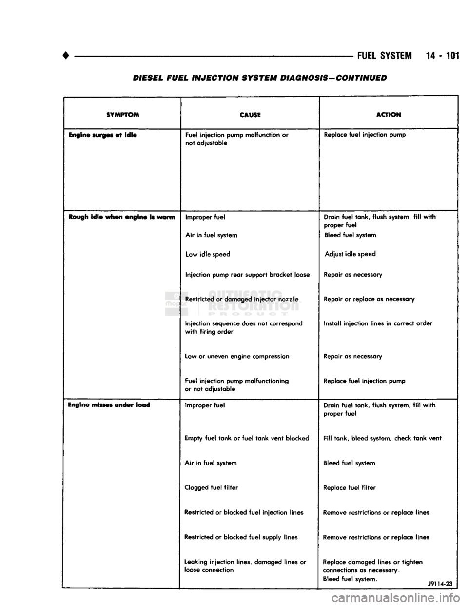
•
FUEL
SYSTEM
14 - 101
DIESEL FUEL
INJECTION
SYSTEM DIAGNOSIS-CONTINUED
SYMPTOM
CAUSE
ACTION
Engine
surges
at
idle
Fuel
injection
pump malfunction or
not adjustable Replace
fuel
injection
pump
Rough
idle
when engine Is warm Improper
fuel
Air in
fuel
system Drain
fuel
tank, flush system,
fill
with
proper
fuel
Bleed
fuel
system
Low
idle
speed Adjust
idle
speed
Injection
pump
rear
support bracket loose Repair as necessary
Restricted or damaged
injector
nozzle
Repair or replace as necessary
Injection
sequence does not correspond
with
firing
order Install
injection
lines in correct order
Low or uneven engine compression Repair as necessary
Fuel
injection
pump malfunctioning
or not adjustable Replace
fuel
injection
pump
Engine
mines under lead Improper
fuel
Drain
fuel
tank, flush system,
fill
with
proper
fuel
Empty
fuel
tank
or
fuel
tank
vent
blocked
Fill
tank, bleed system, check
tank
vent
Air in
fuel
system Bleed
fuel
system
Clogged
fuel
filter
Replace
fuel
filter
Restricted or blocked
fuel
injection
lines Remove restrictions or replace lines
Restricted or blocked
fuel
supply lines Remove restrictions or replace lines
Leaking
injection
lines, damaged lines or
loose
connection Replace damaged lines or
tighten
connections as necessary. Bleed
fuel
system. 1
J9114-23
Page 921 of 1502
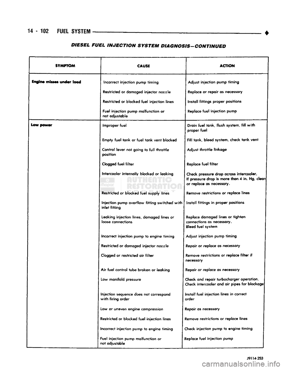
14
- 102
FUEL
SYSTEM
—
•
SYMPTOM
CAUSI
ACTION
lupin*
mimes under Im4 Incorrect
injection
pump
timing
Adjust
injection
pump
timing
Restricted
or
damaged
injector
nozzle
Replace
or
repair
as
necessary
Restricted
or
blocked
fuel
injection
lines Install
fittings
proper positions
Fuel
Injection
pump malfunction
or
not adjustable
Replace
fuel
injection
pump
lew power Improper
fuel
Drain
fuel
tank, flush
system,
fill
with
proper
fuel
Empty
fuel
tank or
fuel
tank vent blocked
Fill
tank, bleed
system,
check tank vent
Control lever not going
to full throttle
position Adjust
throttle
linkage
Clogged
fuel
filter
Replace
fuel
filter
Intercooler
internally
blocked
or
leaking
Check
pressure
drop
across
intercooler.
If
pressure
drop is more than
4
in.
Hg,
clean
or replace
as
necessary.
Restricted
or
blocked
fuel
supply lines
Remove
restrictions
or
replace lines
Injection
pump overflow
fitting
switched
with
inlet
fitting
Install
fittings
in
proper positions
Leaking
injection
lines, damaged lines
or
loose
connections
Replace
damaged
lines
or
tighten
connections
as
necessary.
Bleed
fuel
system
Incorrect
injection
pump
to
engine
timing
Adjust
injection
pump
timing
Restricted or
damaged
injector
nozzle
Repair
or replace as
necessary
Clogged
or
restricted
air filter
Remove
restrictions
or
replace
filter if
necessary
Air
fuel
control
tube broken
or
leaking
Repair
or replace
as
necessary
Low
manifold pressure
Check
and repair turbocharger operation.
Check
intercooler and
air
pipes
for
blockage
Injection
sequence
does
not correspond
with
firing
order Install
fuel
injection
lines in correct
order
Low
or
uneven
engine
compression
Repair
as
necessary
Restricted or blocked
fuel
injection
lines
Remove
restrictions
or
replace lines
Incorrect
injection
pump
to
engine
timing
Check
injection
pump
to
engine
timing
Fuel
injection
pump malfunction
or
not adjustable
Replace
fuel
injection
pump J9114-253
DIESEL
FUEL
INJECTION
SYSTEM
DIAGNOSIS-CONTINUED
Page 922 of 1502
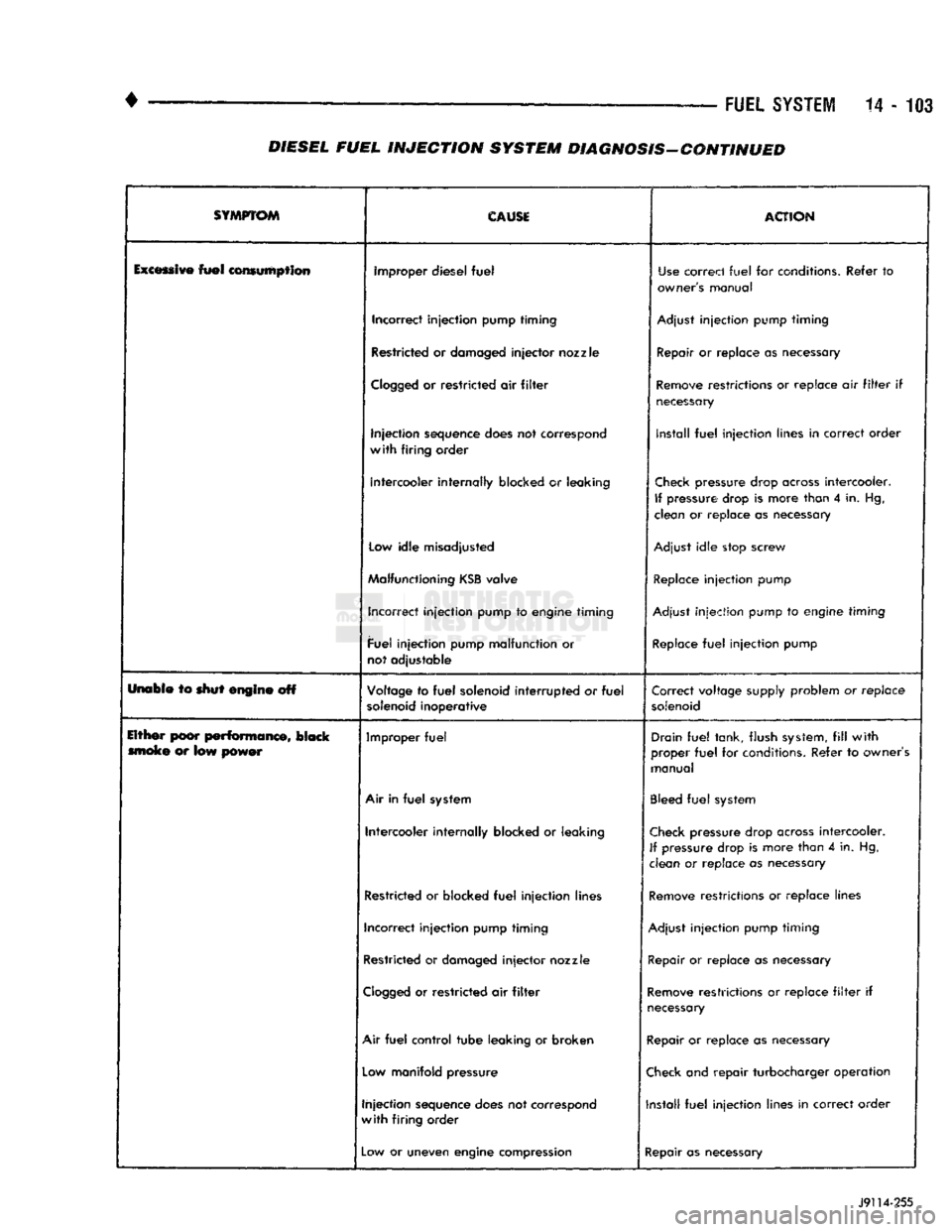
FUEL
SYSTEM
14-103
DIESEL FUEL
INJECTION
SYSTEM DIAGNOSIS-CONTINUED
SYMPTOM
CAUSE
ACTION
Excessive
fuel
consumption improper diesel
fuel
Use
correct
fuel
for conditions. Refer
to
owner's manual
Incorrect injection pump timing
Adjust
injection pump timing
Restricted or damaged
injector
nozzle Repair or replace as necessary
Clogged
or
restricted air
filter
Remove
restrictions or replace air
filter
if
necessary
Injection sequence does not correspond
with
firing order install
fuel
injection lines in correct order
Intercooler internally blocked
or
leaking
Check
pressure drop
across
intercooler.
If
pressure drop
is
more than
4
in. Hg,
clean or replace as necessary
Low
idle misadjusted
Adjust
idle stop screw
Malfunctioning
KSB
valve
Replace
injection pump
Incorrect injection pump to engine timing
Adjust
injection pump to engine timing
Fuel injection pump malfunction or
not adjustable
Replace
fuel
injection pump
Unabie to shut engine off Voltage to
fuel
solenoid
interrupted
or
fuel
solenoid
inoperative Correct voltage supply problem or
replace
solenoid
Either poor
performance,
black moke
or
low power Improper
fuel
Drain
fuel
tank, flush
system,
fill
with
proper
fuel
for conditions. Refer to owner's
manual
Air
in
fuel
system
Bleed
fuel
system
Intercooler internally blocked
or
leaking
Check
pressure drop
across
intercooler.
If
pressure drop is more than
4
in. Hg,
clean
or
replace
as
necessary
Restricted or blocked
fuel
injection lines
Remove
restrictions or replace lines
Incorrect injection pump timing
Adjust
injection pump timing
Restricted or damaged
injector
nozzle
Repair
or replace as necessary
Clogged
or restricted air
filter
Remove
restrictions or replace
filter
if
necessary
Air
fuel
control tube leaking or broken Repair or replace as necessary
Low
manifold pressure
Check
and repair turbocharger operation
Injection sequence does not correspond
with
firing order Install
fuel
injection lines in correct order
—
Low
or uneven engine compression
Repair as necessary
J9114-255