Page 1057 of 1164

GENERAL INFORMATION
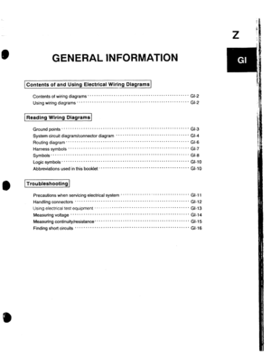
Contents of and Using Electrical Wiring Diagrams
Contents of wiring diagrams . . . . . . . . . . . . . ..I.............................
Using wiring diagrams * * * * * . * * . . . . . . . . . . . . . ..I..........................
I
( Reading Wiring Diagrams
* GI-2
* GI-2
Ground points . * .........................................................
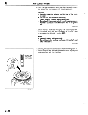
GI-3
System circuit diagram/connector diagram * * . * ..............................
GI-4
Routing diagram ............................... ..........................
GI-6
Harness symbo,s ................................. ....................... G,-,
Symbols”““” ........................................................
GI-8
Logic symbols ...........................................................
GI-10
Abbreviationsusedinthisbook,et..........................................GI-, 0
Troubleshooting
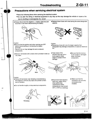
Precautionswhenservicingelectricalsystem”””””””““““““““” GI-11
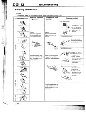
Handling connectors .....................................................
GI-12
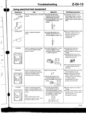
“sing electrical test equipment ............................................. Gl-13
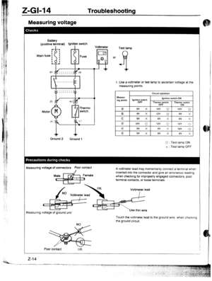
Measuring voltage .......................................................
GI-14
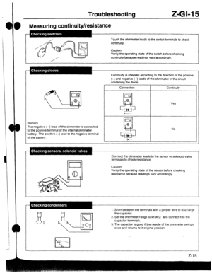
Measuring continuity/resistance ............................................
GI-15
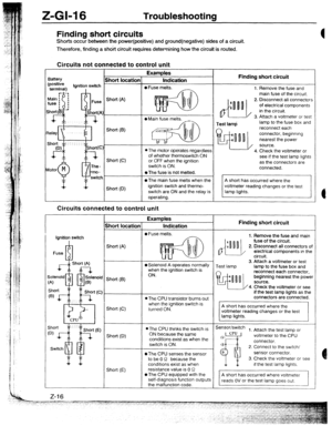
Finding short circuits .....................................................
GI-16
Page 1058 of 1164

Z-Gl-2 Contents of and Using Electrical Wiring Diagrams
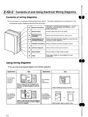
Contents of wiring diagrams
l This document is composed of the 8 groups shown below. The main components are summarized in the
components location diagram at the end of the document.
Tells how to: use and read wiring dragrams, use test
GI General information equipment, check harnesses and connectors, and
locate trouble spots.
Y Ground points Ground routes from and to the battery.
I
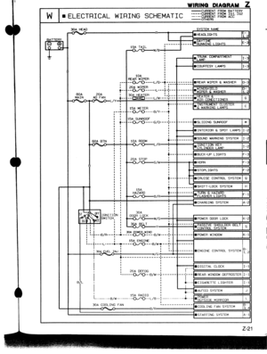
w
I Electrical wiring
schematic
I Shows main and other fuses for each system.
lndlvidual systems
I Shows circuit and connector diagrams, component and
connector location diagrams.
1
X
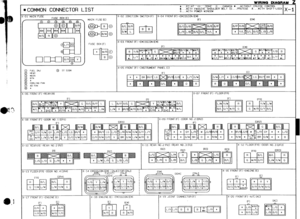
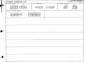
I Common connectors
I Shows connectors common throughout system.
I
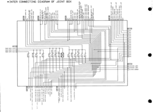
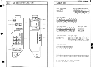
JB Joint box diagrams Shows internal circuits and connectors.
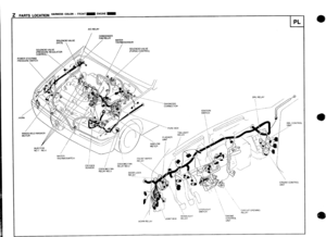
PL Parts location Shows location of major electrical parts.
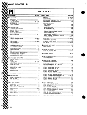
PI Index
I
I
Gives page number of circuit diagram for each
component.
Using wiring diagrams
l The use of the wiring diagram depends on its intended application. Application
For checking
circuits of
individual
systems
For checking
ground circuit
of individual
systems 7-3 Use
II Application
Open to page with circuit diagram and
harness routing to be used and fold out
common connector diagram or joint box
diagram. For checking
fuse
connections Use
Open to electrical wiring schematic.
Open to page with ground point diagram
and fold out common connector diagram
or joint box diagram. For locating
page numbers
of systems and
components Parts Index
H
Open to parts index or system index.
Page 1059 of 1164
I
E
,
1
I
i
t
1
I
!
!
I
t:
I.
1.
i
i
Reading Wiring Diagrams Z-Gl-3
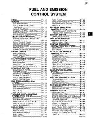
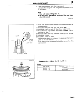
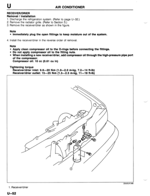
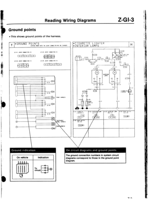
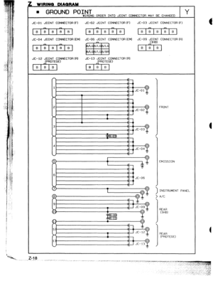
Ground points
l This shows ground points of the harness.
CIGARETTE LIGHTER
INTERIOR LAMPS
H
I On vehicle
I Indication
I
To circuit The ground connection numbers in system circuit
diagrams correspond to those in the ground point
diagram.
Page 1060 of 1164

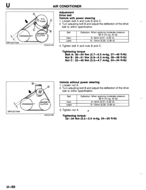
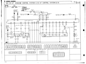
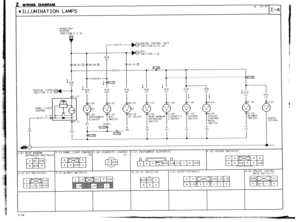
Z-Gl-4 Reading Wiring Diagrams
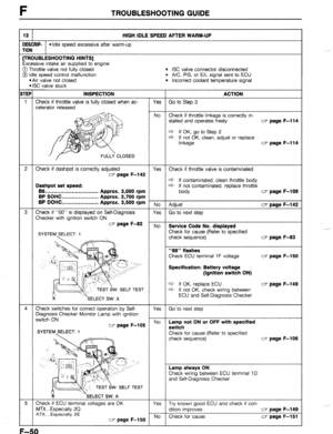
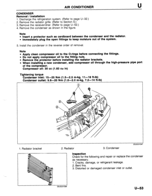
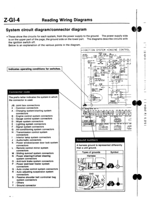
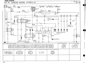
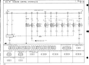
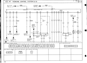
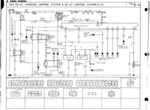
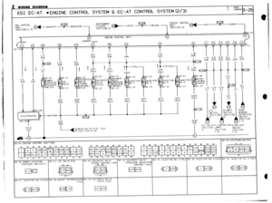
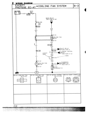
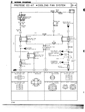
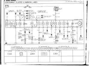
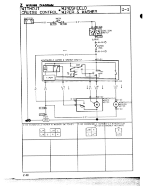
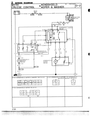
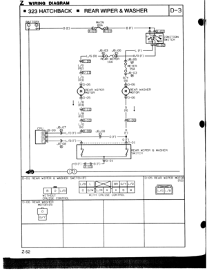
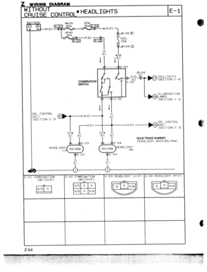
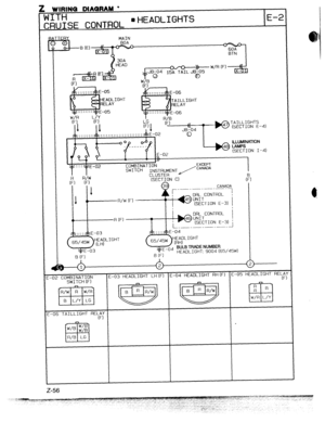
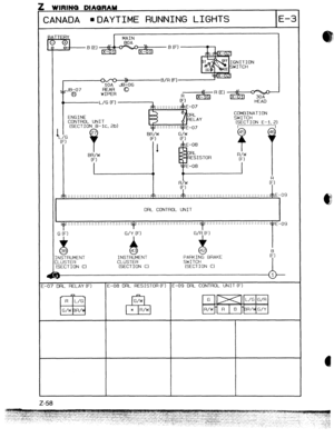
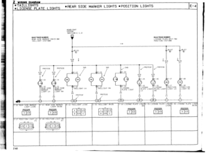
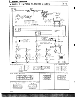
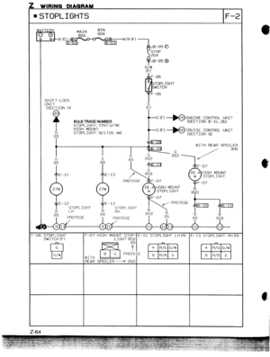
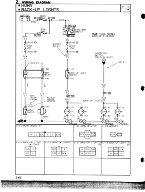
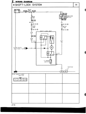
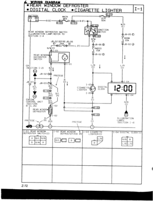
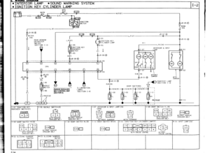
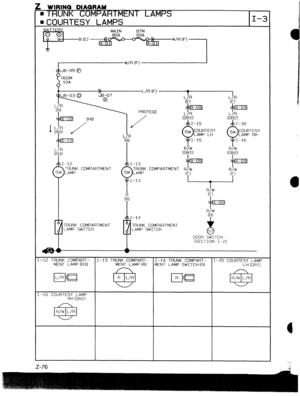
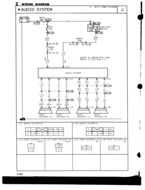
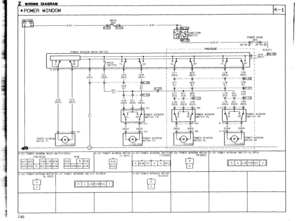
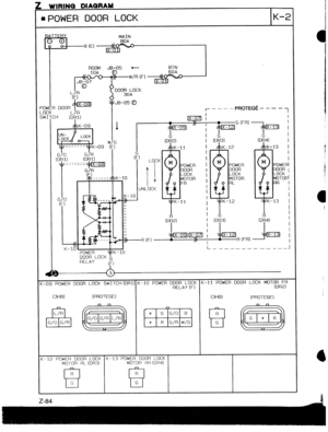
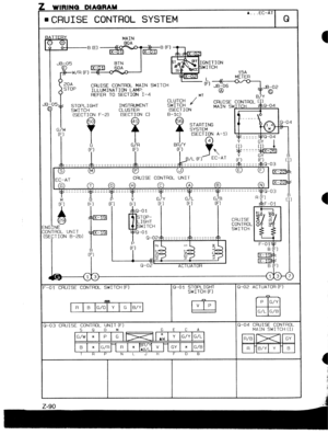
System circuit diagram/connector diagram
l These show the circuits for each system, from the power supply to the ground. The power supply side
is on the upper part of the page, the ground side on the lower part. The diagrams describe circuits with
the ignition switch off.
Below is an explanation of the various points in the diagram.
) Indicates operating conditions for switches.
The prefix letter indicates the system in which
:he connector is used.
JB: Joint box connections
X : Common connectors
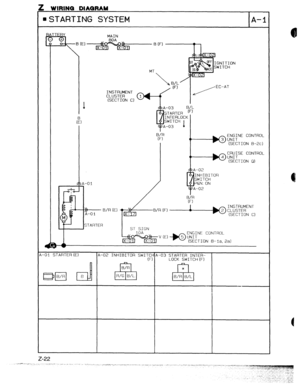
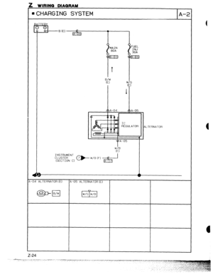
A : Charging system/starting system
connectors
B : Engine control system connectors
C : Gauge control system connectors
D : Wiper system connectors
E : Lighting system connectors
F : Signal system connectors
G : Air-conditioning system connectors
H : Transmission control system
connectors
I : Interior lamp system connectors
J : Audio/radio connectors
K : Power window/power door lock system
connectors
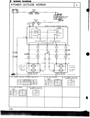
L : Remote control mirror system
connectors
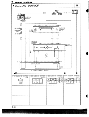
M : Sliding sunroof system connectors
N : Power steering/4-wheel steering
system connectors
0 : Anti-lock brake system connectors
P : Power seat/seat heater system
connectors
Cl : Auto cruise control system connectors
R : Auto adjusting suspension system
connectors
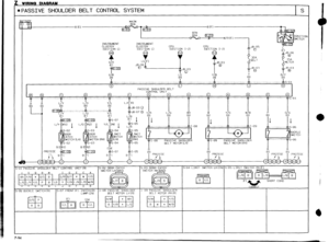
S : Passive shoulder belt control/air bag
system connectors
T : Others
Y : Ground connector
- .
1
\\‘
IGNITION SYSTEM l ENGINE CONTROL 9 harness ground is represented differently
:han a unit ground.
Types of grounds Symbol
Harness
I
-
-
-
-
‘“G:
si-
P
7:’
.I
I
I
.i
-
-
-
f
9
Tiii
zs
LL
Y
a
EE
-
Page 1061 of 1164

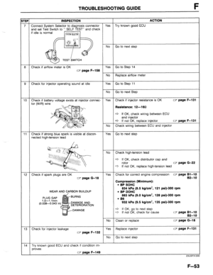
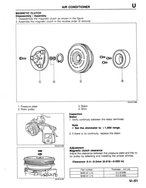
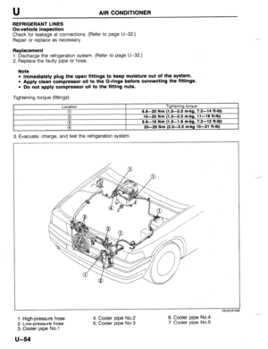
Reading Wiring Diagrams Z-GI-5
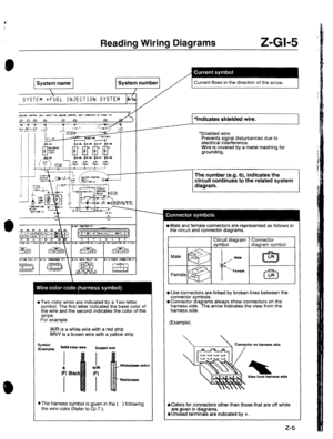
System name
SYSTEM l FUEL INJECTION SYSTEM f
B-lc py,p -
Current flows in the direction of the arrow.
L
::::y...:::..: ::::;IF::::::I::::.:I:I~-. I :I::- .::
F
~~-;..~~~-~-~~~-~-~-~-~-~~~~~-:~-. t /
*Indicates shielded wire.
*Shielded wire:
Prevents signal disturbances due to
electrical interference.
Wire is covered by a metal meshing for
grounding.
*Two-color wires are indicated by a Two-letter
symbol. The first letter indicates the base color of
the wire and the second indicates the color of the
stripe.
For example
W/R is a white wire with a red strip
BR/Y is a brown wire with a yellow strip
Symbol
(Example) solid color wire
Striped wire
Red&ripe)
l
The harness symbol is given in the (
the wire color (Refer to GI-7.). ) following The number (e.g. 6), indicates the
circuit continues to the related system
diagram.
0 Male and female connectors are represented as follows in
the circuit and connector diagrams.
C3r3r;$,diagram
l Like connectors are linked by broken lines between the
connector symbols.
oconnector diagrams always show connectors on the
harness side. The arrow Indicates the view from the
harness side.
(Example)
View horn harness ride
@Colors for connectors other than those that are off white
are given in dia rams.
0 Unused termrn d s are
indicated by $ .
Page 1062 of 1164
z-GI-6 Reading Wiring Diagrams
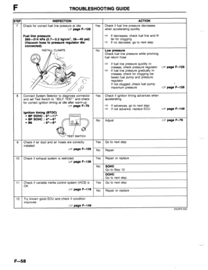
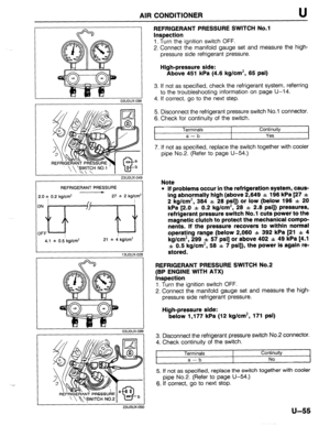
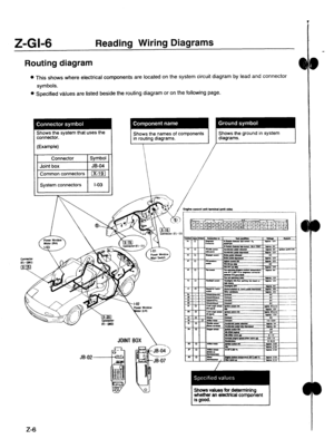
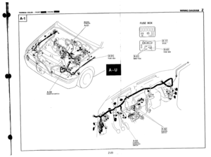
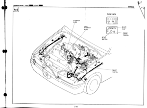
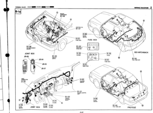
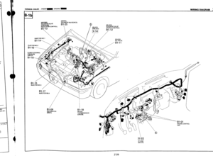
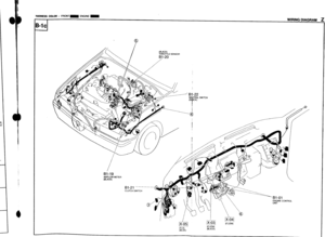
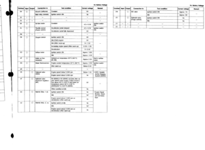
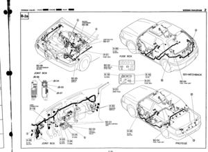
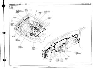
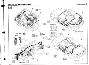
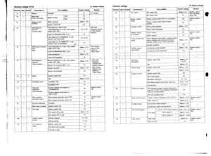
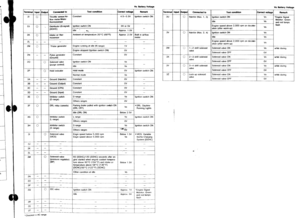
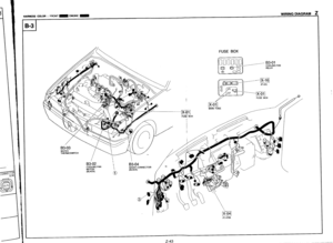
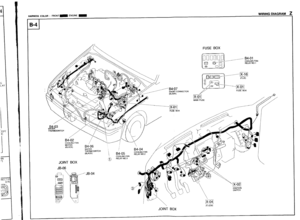
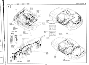
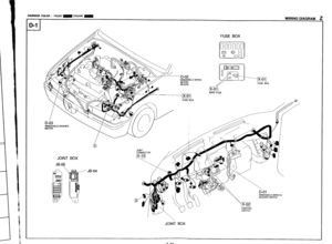
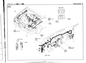
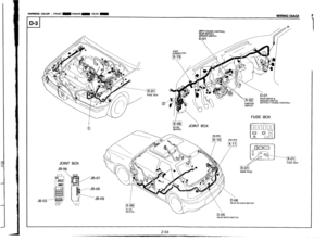
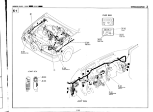
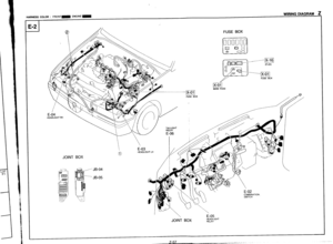
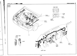
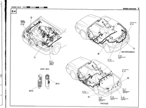
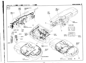
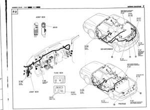
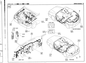
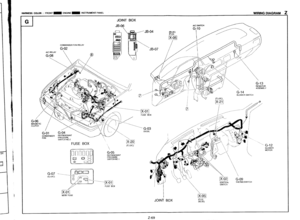
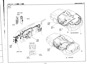
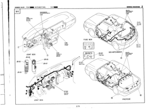
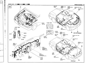
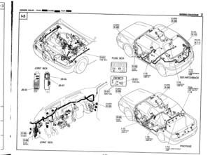
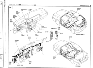
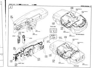
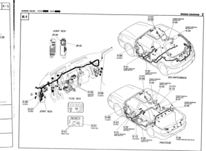
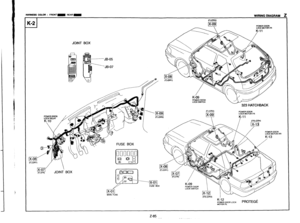
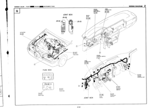
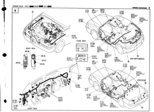
Routing diagram
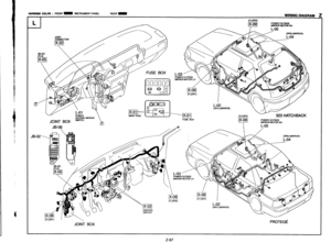
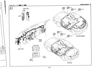
l This shows where electrical components are located on the system circuit diagram by lead and connector
symbols.
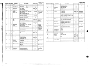
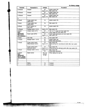
l Specified values are listed beside the routing diagram or on the following page.
Shows the system that uses the
connector.
Shows the names of components in routing diagrams.
(Example)
I Connector 1 Symbol 1
Joint box JB-04
Common connectors lXi?U
System connectors I-03 Shows the ground in system diagrams.
JOINT Shows values for determining
whether an electrkal component
is good.
Z-6
Page 1063 of 1164
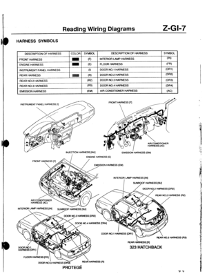
Reading Wiring Diagrams Z-GI-7
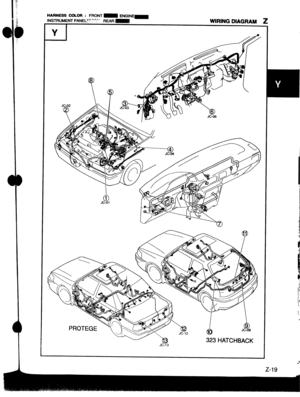
HARNESS SYMBOLS
DESCRIPTION OF HARNESS
FRONT HARNESS
ENGINE HARNESS
INSTRUMENT PANEL HARNESS
REAR HARNESS
REAR NO.2 HARNE COLOR SYMBOL DESCRIPTION OF HARNESS SYMBOL
(F) INTERIOR LAMP HARNESS (IN)
(El FLOOR HARNESS
FW
(1) DOOR NO.1 HARNESS Ml)
DOOR NO.2 HARNESS
WW
EMISSION HARNESS AIR CONDITIONER HARNESS
INSTRUMENT PANEL HARNESS
FRONT HARNESS [a ,&<\I INJECTION HARNESS [INJ]
EMISSION’ HARNESS (EM)
I ENGINE HARNESS [E]
/
EMISSION HARNESS (EM)
INTERlOq IAMP HARNESS [IN]
- INTERlO? LAMP HARNESS [IN]
SUNRGOF GESS [SU]
REAR HklNESS [R]
323 HATCHBACK
IARNESS (R3)
FL00F4 HAdNEss(FR1 -,A HARNESS (Rl DOOR NO.3 HARNESS [DRS]
PROTE&
Page 1064 of 1164

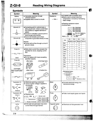
Z-Gl-8 Reading Wiring Diagrams
Svmbols I
Symbol Meaning Symbol Meaning
Battery (I, Generates electricity through Resistance l A resistor with a constant value
chemical reaction l Mainly used to protect electrical
l Supplies direct current to circuits components in circuits by maintaining
rated voltage
l Reading resistance values
Ground (1)
l Connecting point to vehicle body or No.1 Cobr band
-A- other ground wire where current flows -No.2 Cobr band
from positive to negative terminal of -No.3 Cobr band
battery No.4 Cobr band
1
l Ground (1) indicates a ground point to Flnt color. Rerkrancs
body through wire harness
Ground (2) l Gound (2) indicates point where
component is grounded directly to body
Remark
oCurrent wilt not flow through a circuit if
ground is faulty
Fuse (1)
(box)
Fuse (2)
l Melts when current flow exceeds that
specified for circuit, stopping current
flow
Precautions
o Do not replace with fuses exceeding
specified capacity
.
(Cartridge)
vlain fuse/Fusible
Transistor (1)
l Electrical switching component
a Turns on when voltage is applied to Motor
0 Converts electrical energy into
mechanical energy
Transistor (2)
coiibmr (Cl
l Reading code l Pulls in and expels gases and liquids
Lamp
Number of terminals O:Low- frequency NPN
l Emits light and generates heat when
Cigarette lighter
current flows through filament a Electrical coil that generates heat