2006 LAND ROVER FRELANDER 2 key
[x] Cancel search: keyPage 2313 of 3229
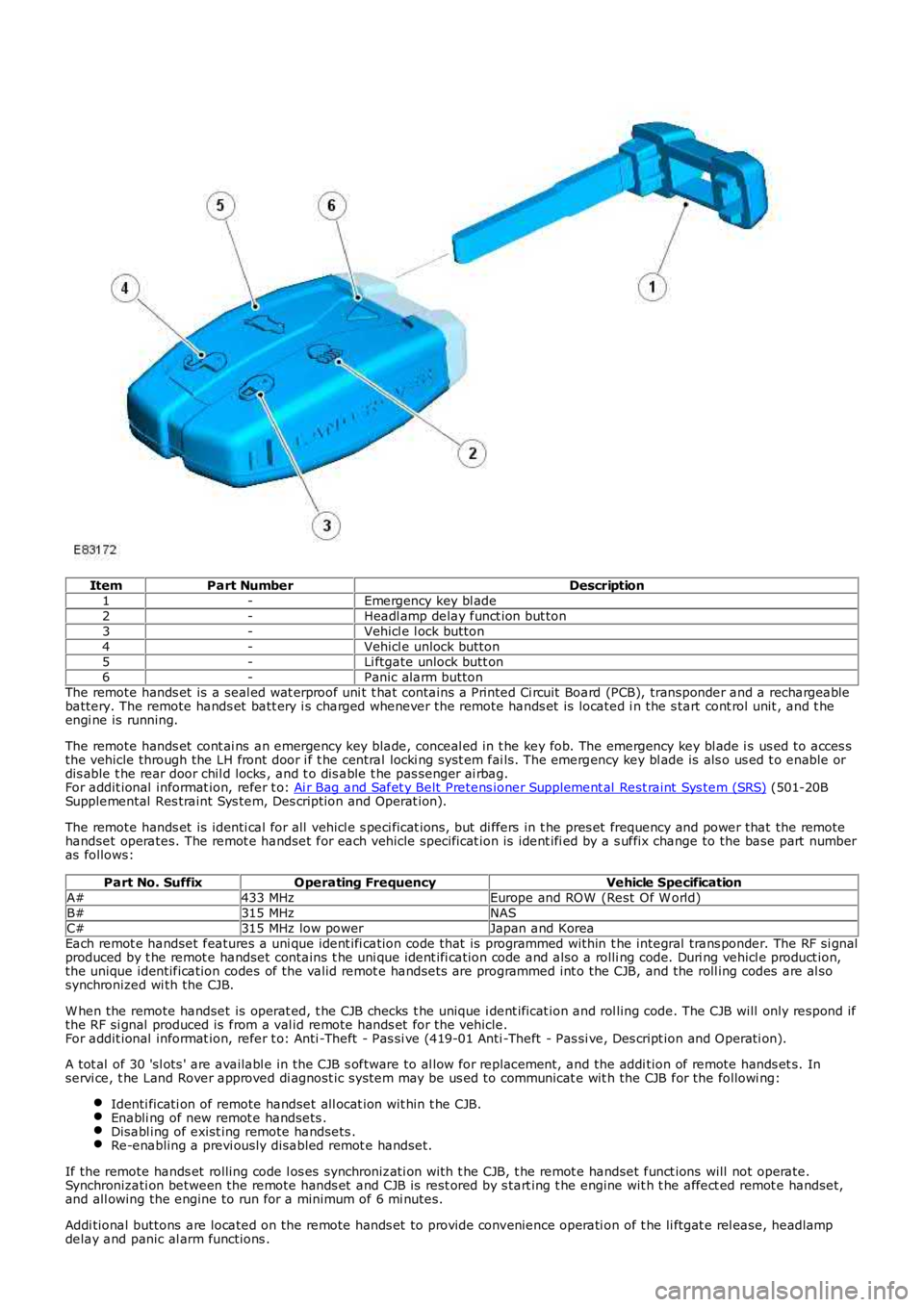
ItemPart NumberDescription1-Emergency key bl ade2-Headl amp delay funct ion but ton3-Vehicl e l ock button4-Vehicl e unlock button5-Li ftgate unlock butt on6-Panic alarm buttonThe remote hands et is a seal ed wat erproof uni t t hat contains a Printed Ci rcuit Board (PCB), transponder and a rechargeablebattery. The remote hands et batt ery i s charged whenever the remote hands et is located i n the s tart cont rol unit , and t heengi ne is running.
The remote hands et cont ai ns an emergency key blade, conceal ed in t he key fob. The emergency key bl ade i s us ed to acces sthe vehicle through the LH front door i f t he central locki ng syst em fai ls. The emergency key bl ade is als o us ed t o enable ordis able t he rear door chil d locks , and t o dis able t he pas senger ai rbag.For addit ional informat ion, refer t o: Ai r Bag and Safet y Belt Pretens ioner Supplement al Rest raint Sys tem (SRS) (501-20BSupplemental Res traint Sys tem, Des cription and Operat ion).
The remote hands et is identi cal for all vehicl e s peci ficat ions, but di ffers in t he pres et frequency and power that the remotehandset operates. The remot e handset for each vehicle specificat ion is ident ifi ed by a s uffix change to the base part numberas follows:
Part No. SuffixOperating FrequencyVehicle SpecificationA#433 MHzEurope and ROW (Rest Of W orld)B#315 MHzNASC#315 MHz low powerJapan and KoreaEach remot e handset features a uni que ident ifi cation code that is programmed within t he integral trans ponder. The RF si gnalproduced by t he remot e handset contains t he uni que ident ifi cation code and also a rolli ng code. Duri ng vehicl e product ion,the unique identification codes of the valid remot e handsets are programmed int o the CJB, and the roll ing codes are al sosynchronized wi th the CJB.
W hen the remote handset is operat ed, t he CJB checks t he unique i dent ificat ion and rol ling code. The CJB will only respond ifthe RF si gnal produced is from a val id remote hands et for the vehicle.For addit ional informat ion, refer t o: Anti -Theft - Pas si ve (419-01 Anti -Theft - Pas si ve, Des cript ion and Operati on).
A tot al of 30 'sl ots ' are availabl e in the CJB s oftware to al low for repl acement, and the addi tion of remote hands et s. Inservi ce, t he Land Rover approved di agnost ic system may be us ed to communicat e wit h the CJB for the followi ng:
Identi ficati on of remote handset all ocat ion wit hin t he CJB.Enabli ng of new remot e handsets .Disabl ing of exist ing remote handsets .Re-enabling a previ ously disabled remot e handset.
If the remote hands et rolling code l os es synchronizati on with t he CJB, t he remot e handset funct ions will not operate.Synchronizati on between the remote hands et and CJB is rest ored by s tart ing t he engine wit h t he affect ed remot e handset,and all owing the engine to run for a minimum of 6 mi nutes.
Addi tional buttons are located on the remote hands et to provide convenience operati on of t he li ftgat e rel ease, headlampdelay and panic al arm functions .
Page 2320 of 3229
Publi s hed: 22-Nov-2011
Handles, Locks, Latches and Entry Systems - Locks, Latches and Entry
Systems
Diagnosi s and Tes ti ng
Principle of Operation
For a detail ed descripti on of the locks , lat ches and ent ry s ys tems and operat ion, refer to the relevant Des cri pt ion andOperat ion s ect ion of t he works hop manual. REFER to: Handles , Locks , Lat ches and Ent ry Sys tems (501-14 Handles , Locks ,Latches and Ent ry Sys t ems, Des cri pt ion and Operati on).
Inspection and Verification
CAUTION: Di agnos is by s ubs ti tut ion from a donor vehicle is NO T acceptabl e. Subs ti tut ion of cont rol modules doesnot guarant ee confirmat ion of a faul t and may al so caus e addit ional fault s in the vehicle bei ng checked and/or the donorvehi cl e.
• NOTE: Check and recti fy bas ic faul ts before beginni ng diagnos t ic rout ines i nvol vi ng pinpoint t es t s.
1. Verify t he cus t omer concern.1.
2. Vis ually ins pect for obvious s igns of mechani cal or electrical damage.2.
Visual Inspection
MechanicalElectricalIncorrectl y aligned door(s ), hood or tai lgateFuel fil ler door lock act uat orHood rel ease handleHood rel ease cablesHood l at ch(es )Exterior door handle(s)Interi or door handle(s )Cable(s)Tail gat e release swit chRear window release s wit ch
Fus esW i ri ng harnessW i ri ng connect or(s )Door l ock act uat or(s )Remote trans mi tt er (key-fob or smart key)Cent ral l ocking s wi tchesCont rol ler Area Net work (CAN) circui tsRadi o frequency (RF) recei verCent ral junct ion box (CJB)Loos e or corroded connect ions
3. If an obvious cause for an obs erved or report ed concern is found, correct t he caus e (if pos s ible) beforeproceeding t o t he next s t ep.3.
4. If t he caus e is not vis ually evi dent , verify t he sympt om and refer t o t he Sympt om Chart, al ternat ively check forDi agnos ti c Trouble Codes (DTCs) and refer t o t he DTC Index.4.
Symptom Chart
SymptomPossible causesActionDoor(s ) wil l not openfrom out s ideExt erior door handl econdit ion/i nst all at ionExt erior release cabl edi s connect ed from ext eriordoor handl e or door l atchDoor l at ch fai lure
Check the ext eri or door handl e condi ti on andi nst all at ionCheck the condit ion and s ecurit y of t he ext eri orreleas e cabl eCheck the operat ion of t he l at ch GO to Pi npoi nt Tes tA.
Door(s ) wil l not openfrom ins ideChi ld l ock(s) engagedInt erior door handlecondit ion/i nst all at ionInt erior rel ease cabledi s connect ed from interiordoor handl e or door l atchDoor l at ch fai lure
Check that t he chi ld locks are dis engagedCheck the interior door handle condit ion andi nst all at ionCheck the condit ion and s ecurit y of t he int eriorreleas e cabl eCheck the operat ion of t he l at ch. GO t o Pinpoint Tes tA.
The mes s age cent eri ndi cat es that t he hood,t he tai lgate or a door i sopen when it appears t obe clos ed
Incorrect s trikeral ignment/adjus tmentAjar s wit ch ci rcuit s hortci rcuit t o groundAjar s wit ch fail ure
Check/adjus t the st ri kers as neces s aryCheck for DTCs i ndi cat ing an ajar swit ch fault . Refert o t he DTC i ndex
Vehicle indicates ami s s-lock when t hehood, t ail gat e and doorsappear t o be clos ed
Fuel flap does notl ock/unlockFuel fl ap cabl e detached frombodyFuel fl ap act uator detachedfrom mounti ng bracketFuel fl ap act uatordi s connect edFuel fl ap act uator fai lure
Check the condit ion and i nst all at ion of t he fuel flapcableCheck the securi ty of t he fuel flap actuat or andbracketCheck the securi ty of t he actuator elect ricalconnect orCheck for DTCs i ndi cat ing a fuel fl ap act uator faul t.Refer t o t he DTC i ndex
Page 2321 of 3229
1
2
1
SymptomPossible causesAction
Door lat chi ng andl ocking funct ion t es tDoor l at chCabl e faultDoor handleDoor l ock s wi tchW iring harnes sCent ral juncti on box (CJB)
• NOTE: Complete the diagnostic steps below to confirmany concern prior replacing the component
Check for relevant s t ored DTCsOnce any DTC relat ed fault s have been recti fi edconti nue wit h t he diagnos t ic s t eps bel owThe firs t component that s houl d be checked whenexperi encing l ocki ng or latching i s sues are t he doorl atch release cables , t hen the door lat ch. These canbe tes ted as a dis crete components to confi rm if t hes peci fi c component is working as des igned or isdemons trati ng a faul tSingle door will not open from the outside (butopens from the inside)GO t o Pi npoi nt Tes t A.Single Door Will Not Open From T he Inside (butopens from the outside)GO to Pi npoi nt Tes t B.Door Latching and Locking Function T estGO t oPi npoi nt Tes t C.No lock / unlock function from key-fobGO t oPi npoi nt Tes t E.
Latch mount ed door ajars wit ch t es tDoor l at chW iring harnes sIns trument cl ust er
Latch Mounted Door Ajar Switch T estGO t oPi npoi nt Tes t D.
Vehicle el ect ri cal s yst emt estFus esW iring harnes sW iring connect or(s)
Vehicle Electrical System T estGO t o Pi npoi nt Tes tE.Check for relevant s t ored DTCsRefer t o t he electrical ci rcuit di agrams t o locate thefaultCarry out cont inui ty t es t to confi rm circui t integrit y
DTC Index
For a li st of Di agnos ti c Trouble Codes (DTCs) t hat coul d be logged on t his vehicle, pleas e refer to Sect ion 100-00.REFER to: Di agnos ti c Trouble Code (DTC) Index - DTC: Body Cont rol Module (BCM) (100-00 General Informat ion,Des cript ion and Operat ion) /Diagnost ic Troubl e Code (DTC) Index - DTC: Dri ver/Pas s enger Door Modul e (DDM/PDM) (100-00 General Informat ion,Des cript ion and Operat ion).
Pinpoint Test
PINPOINT TEST A : SINGLE DOOR WILL NOT OPEN FROM THE OUTSIDE (BUT OPENS FROM THE
INSIDE)
T EST CO NDIT IONSDET AILS/RESULT S/ACT IONSA1: CHECK T HE EXT ERIO R DOOR RELEASE CABLE T O EXT ERIOR DOOR HANDLE IS INST ALLED CORRECT LY
Remove the door trim panel as necess ary.REFER t o: Front Door Trim Panel (501-05 Interior Tri m andOrnamentat ion, Removal and Inst all ati on) /Rear Door Tri m Panel (501-05 Int erior Tri m andOrnamentat ion, Removal and Inst all ati on).
Confirm t he exterior door releas e cabl e is correctl y ins t al ledto the ext erior door handle
Is t he cabl e correct ly i nst all ed?YesGO t o A2.NoConnect the door rel eas e cable correctl y. If the cable isdamaged, install a new door release cable. Tes t t hesys t em for normal operat ion.
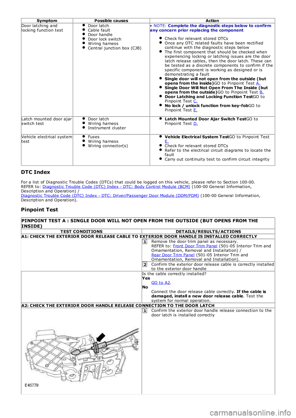
A2: CHECK T HE EXT ERIO R DOOR HANDLE RELEASE CO NNECT ION T O T HE DOOR LAT CHConfirm t he exterior door handle releas e connecti on to thedoor l at ch is ins tal led correct ly
Page 2324 of 3229
10
11
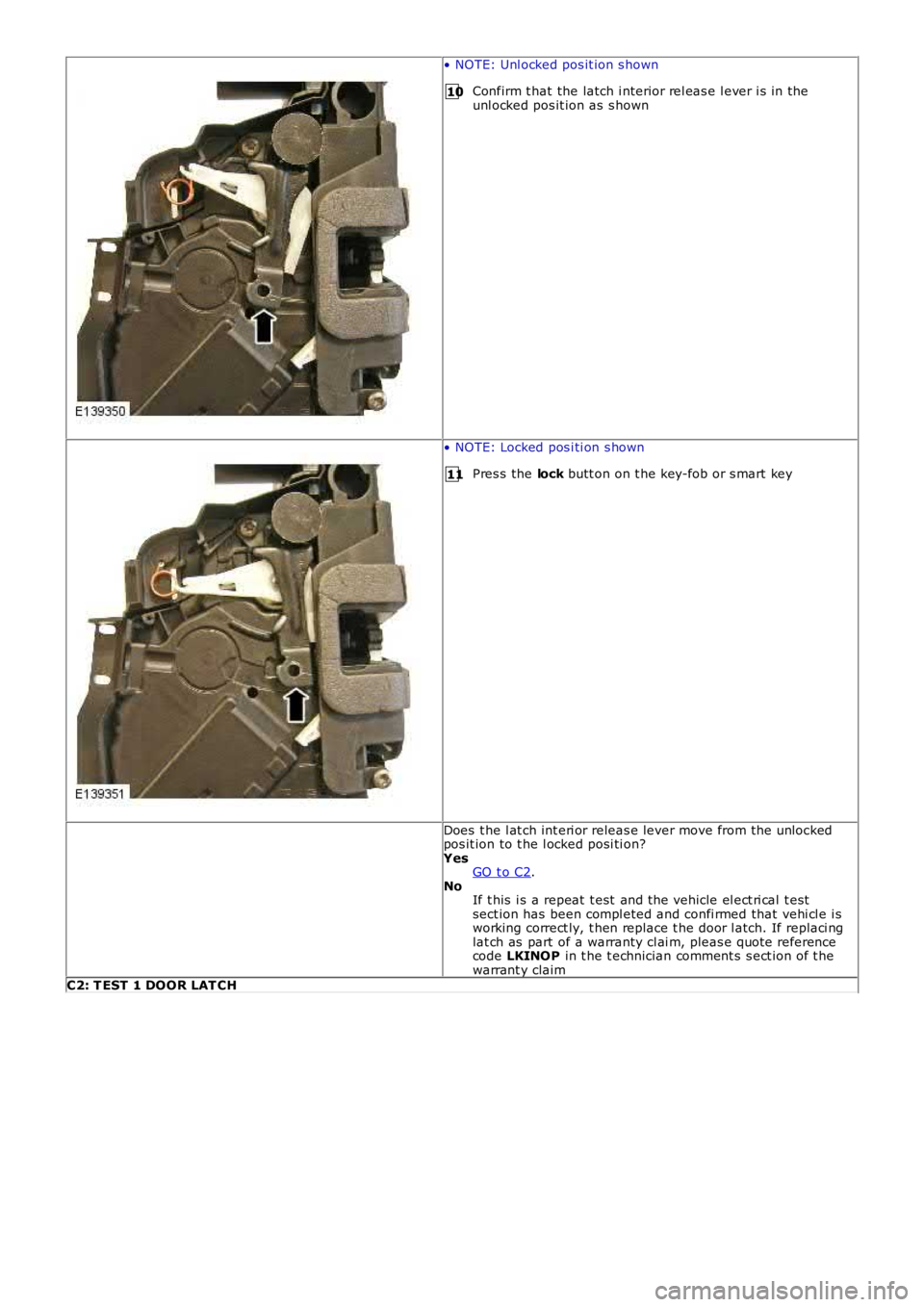
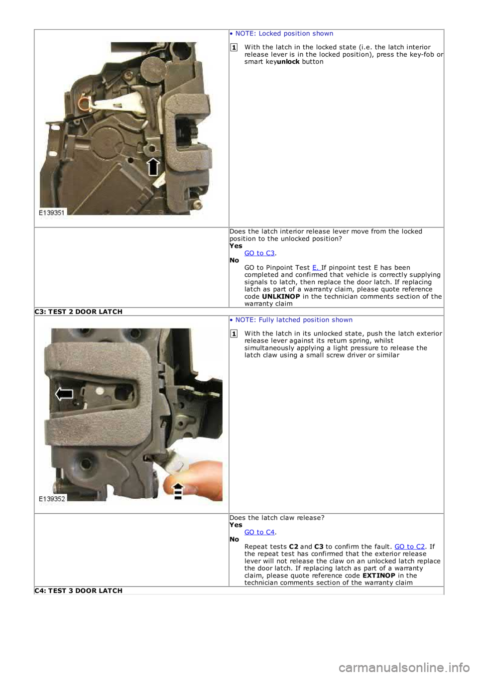
• NOTE: Unl ocked pos it ion s hown
Confirm t hat the latch i nterior rel eas e l ever i s in theunl ocked pos it ion as s hown
• NOTE: Locked pos i ti on s hown
Pres s the lock butt on on t he key-fob or s mart key
Does t he l at ch int eri or releas e lever move from the unlockedpos it ion to t he l ocked posi ti on?YesGO t o C2.NoIf t his i s a repeat t est and the vehicle el ect ri cal t estsect ion has been compl eted and confi rmed that vehi cl e i sworking correct ly, t hen replace t he door l atch. If replaci nglat ch as part of a warranty cl ai m, pleas e quote referencecode LKINOP in t he t echnician comment s s ect ion of t hewarrant y claimC2: T EST 1 DOOR LAT CH
Page 2325 of 3229
1
1
• NOTE: Locked pos i ti on s hown
W i th t he l at ch in the locked s t ate (i.e. the latch i nteriorreleas e l ever is in t he l ocked posi ti on), pres s t he key-fob orsmart keyunlock but ton
Does t he l at ch int eri or releas e lever move from the l ockedpos it ion to t he unlocked pos i ti on?YesGO t o C3.NoGO t o Pinpoint Tes t E. If pinpoint t est E has beencompl eted and confi rmed t hat vehi cl e is correctl y s uppl yi ngsi gnal s t o lat ch, t hen replace t he door latch. If replacinglat ch as part of a warranty cl ai m, pleas e quote referencecode UNLKINOP in the t echnici an comment s s ect ion of t hewarrant y claim
C3: T EST 2 DOOR LAT CH
• NOTE: Ful ly l atched pos i ti on s hown
W i th t he l at ch in it s unlocked st ate, pus h the latch ext eriorreleas e l ever agains t it s ret urn s pring, whils tsi mult aneous ly applyi ng a l ight pres sure t o rel eas e t helat ch cl aw us ing a smal l screw dri ver or s imilar
Does t he l at ch claw releas e?YesGO t o C4.NoRepeat t es t s C2 and C3 to confi rm t he fault . GO t o C2. Ifthe repeat t es t has confi rmed that t he ext eri or releas elever will not rel ease the claw on an unlocked lat ch replacethe door lat ch. If replacing latch as part of a warrant ycl aim, pl eas e quote reference code EXT INOP in t hetechni cian comments secti on of the warrant y claim
C4: T EST 3 DOOR LAT CH
Page 2329 of 3229
1
2
3
1
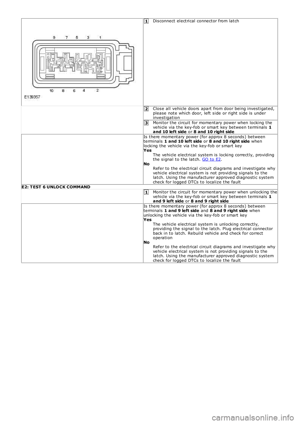
Dis connect el ect ri cal connect or from lat ch
Clos e all vehicle doors apart from door bei ng inves ti gat ed,please not e whi ch door, left s i de or ri ght s ide is underinvest igat ion
Moni tor t he circui t for moment ary power when locki ng t hevehi cl e via t he key-fob or smart key between t ermi nal s 1and 10 left side or 8 and 10 right side
Is t here moment ary power (for approx 8 seconds ) betweenterminals 1 and 10 left side or 8 and 10 right side whenlocki ng the vehicle via t he key-fob or s mart keyYesThe vehi cl e electrical sys tem is locki ng correct ly, providingthe s i gnal t o t he lat ch. GO to E2.NoRefer to the el ect ri cal circui t diagrams and i nves t igate whyvehi cl e electrical sys tem is not provi ding s ignals to t helat ch. Us ing t he manufacturer approved di agnos ti c s ys t emcheck for l ogged DTCs t o l ocali ze t he faultE2: T EST 6 UNLO CK COMMAND
Moni tor t he circui t for moment ary power when unl ocki ng thevehi cl e via t he key-fob or smart key between t ermi nal s 1and 9 left side or 8 and 9 right side
Is t here moment ary power (for approx 8 seconds ) betweenterminals 1 and 9 left side and 8 and 9 right side whenunl ocking t he vehicle vi a t he key-fob or s mart keyYesThe vehi cl e electrical sys tem is unl ocking correctl y,providing t he s ignal to the l atch. Plug elect rical connectorback i n t o lat ch. Rebuil d vehi cl e and check for correctoperati onNoRefer to the el ect ri cal circui t diagrams and i nves t igate whyvehi cl e electrical sys tem is not provi ding s ignals to t helat ch. Us ing t he manufacturer approved di agnos ti c s ys t emcheck for l ogged DTCs t o l ocali ze t he fault
Page 2452 of 3229
Publi s hed: 21-Nov-2011
Safety Belt System - Safety Belt System
Diagnosi s and Tes ti ng
Principle of Operation
For a detail ed descripti on of the safet y belt s ys tem and operati on, refer t o t he relevant des cri pti on and operati on s ect ionof the workshop manual REFER to: Safet y Belt Sys tem (501-20A Safety Bel t Sys t em, Des cri pti on and Operati on).
Safety Information
• W ARNINGS:
To avoid accidental depl oyment t he back-up power supply must be depl et ed before begi nning any work on the SRSs ys t em or i ts component s . Fai lure to foll ow t his i nst ruct ion may res ul t in pers onal injury
Do not us e a mult imet er to probe an SRS module. It is pos s ible for the power from the mult imet er bat tery t o triggert he act ivati on of the modul e. Fai lure to foll ow t his i ns t ructi on may resul t in personal injury
• NOTE: Do not t o us e a cell ul ar phone or t o have a cell ul ar phone i n clos e proximity when worki ng on the SRS sys t em orcomponents
Power supply deplet ion
Before begi nni ng any work on the SRS sys tem or rel at ed component s:
1. Remove the i gnit ion key1.
2. Dis connect the bat tery leads , ground fi rs t2.
3. W ait 2 mi nut es for t he power ci rcuit t o dis charge3.
There are comprehens i ve ins truct ions on t he correct procedures for SRS s ys tem repairs , refer t o t he rel evant s ect ion of t heworks hop manual
Inspection and Verification
CAUTION: Di agnos is by s ubs ti tut ion from a donor vehicle is NO T acceptabl e. Subs ti tut ion of cont rol modules doesnot guarant ee confirmat ion of a faul t and may al so caus e addit ional fault s in the vehicle bei ng checked and/or the donorvehi cl e
• NOTE: Check and recti fy bas ic faul ts before beginni ng diagnos t ic rout ines i ncl udi ng pinpoint t es t s
1. Verify t he cus t omer concern by operat ing t he s afet y belt1.
2. Vis ually ins pect for obvious s igns of mechani cal or electrical damage2.
Visual InspectionMechanicalElectrical
Check for t he ins tal lati on of non-s tandard acces s ori es which may affect orobs truct t he functi on of the safet y belt s ys temFrayed or damaged webbi ngMi ss i ng or damaged but ton s t opPret ensi oner(s ) Buckl es/Stal ks
FusesW iri ng harnes s faultCorrect engagement ofelectrical connect orsLoose or corroded connect ionsW arning l amp bulb(s)Impact s ens or(s )Buckl e s ens or(s )Pret ensi oner(s )Belt t ensi on s ens or(s )Res traints cont rol module
3. If an obvious cause for an obs erved or report ed concern is found, correct t he caus e (if pos s ible) beforeproceeding t o t he next s t ep3.
4. If t he caus e is not vis ually evi dent , carry out t he t es t met hods des cri bed bel ow, alternat ively check fordi agnos ti c troubl e codes and refer t o t he rel evant diagnost ic troubl e code index4.
For a compl ete lis t of all di agnos ti c troubl e codes that coul d be l ogged on t his vehicle, pleas e refer to s ect ion 100-00.REFER to: Di agnos ti c Trouble Code (DTC) Index - DTC: Res trai nts Cont rol Module (RCM) (100-00 General Informati on,Des cript ion and Operat ion).
Symptom Chart for Safety Belt Rows 1, 2 and 3
SymptomPossible CausesActionSafet y belt jammed -W ebbing ti ghtBackl ock effect-in act ion (webbing ret ract ed qui ckl yand came t o s udden st op)Safet y belt ret ract or not i ns t alled correctl yRear cent re bel t onl y. Mini-but t on (webbing travell imi t st op) mis s ing and seat s quab has been moved
GO t o Pi npoint Tes t A.GO t o Pi npoint Tes t F.GO t o Pi npoint Tes t H.See the aut omati c lockingret ractor des cript ion below
Page 2483 of 3229
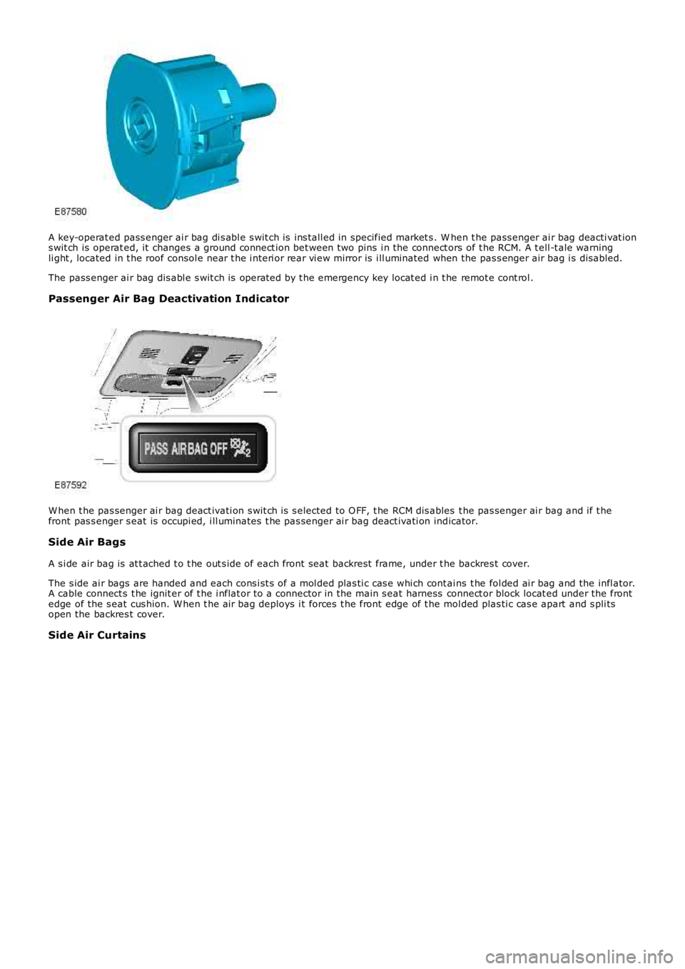
A key-operat ed pass enger ai r bag di s abl e s wit ch is ins tall ed in specified market s . When t he pass enger ai r bag deacti vat ions wit ch is operat ed, it changes a ground connect ion bet ween two pins i n the connect ors of t he RCM. A t ell -t ale warningli ght , located in t he roof consol e near t he i nt eri or rear vi ew mirror is i ll uminated when the pas s enger air bag i s dis abled.
The pass enger ai r bag dis abl e s wit ch is operat ed by t he emergency key locat ed i n t he remot e cont rol .
Passenger Air Bag Deactivation Indicator
W hen t he pas senger ai r bag deact ivati on s wit ch is s elected to O FF, t he RCM dis ables t he pas senger ai r bag and if t hefront pas s enger s eat is occupi ed, i ll uminates t he pas senger ai r bag deact ivati on indicator.
Side Air Bags
A s i de air bag is at t ached t o t he out s ide of each front seat backrest frame, under the backres t cover.
The s ide ai r bags are handed and each cons i st s of a mol ded plas ti c cas e whi ch cont ains t he fol ded ai r bag and the infl ator.A cable connect s t he ignit er of t he i nflat or to a connector in the main s eat harness connect or block locat ed under the frontedge of the s eat cus hion. W hen t he air bag deploys i t forces t he front edge of t he mol ded plas ti c cas e apart and s pli tsopen the backres t cover.
Side Air Curtains