2006 LAND ROVER FRELANDER 2 key
[x] Cancel search: keyPage 1827 of 3229
Publi s hed: 11-May-2011
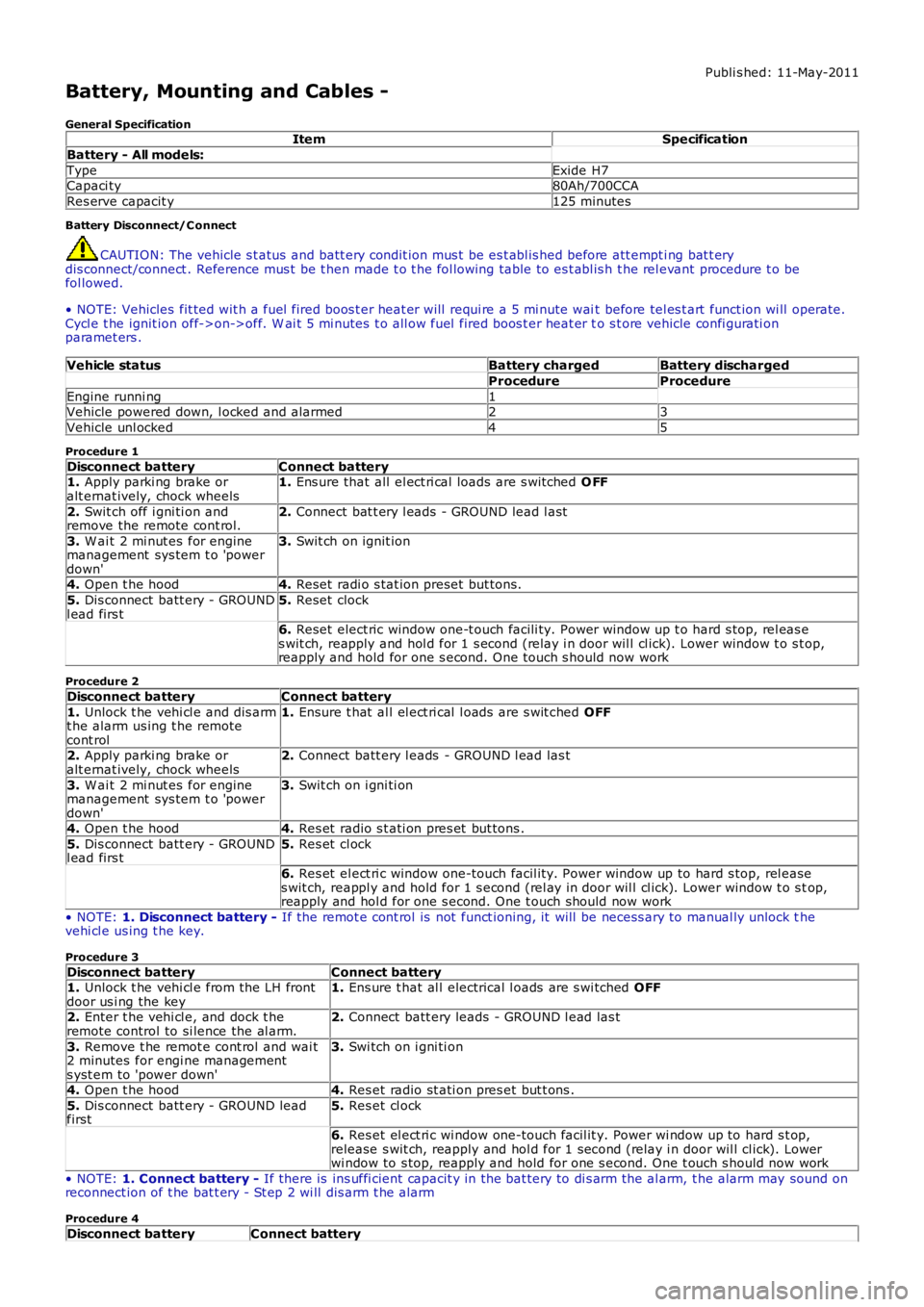
Battery, Mounting and Cables -
General SpecificationItemSpecification
Battery - All models:
TypeExide H7Capaci ty80Ah/700CCA
Res erve capacit y125 minutes
Battery Disconnect/C onnect
CAUTION: The vehicle s t atus and batt ery condit ion mus t be es t abl is hed before att empti ng bat t erydis connect/connect . Reference mus t be t hen made t o t he fol lowing table to es t abl is h t he rel evant procedure t o befol lowed.
• NOTE: Vehicles fit ted wit h a fuel fired boos t er heat er will requi re a 5 mi nute wait before tel es t art funct ion wi ll operate.Cycl e t he ignit ion off->on->off. W ai t 5 mi nutes t o all ow fuel fired boos t er heat er to s t ore vehicle confi gurati onparamet ers .
Vehicle statusBattery chargedBattery discharged
ProcedureProcedure
Engine runni ng1Vehicle powered down, l ocked and alarmed23
Vehicle unl ocked45
Procedure 1
Disconnect batteryConnect battery1. Apply parki ng brake oralt ernat ively, chock wheels1. Ens ure that all el ect ri cal loads are s wit ched O FF
2. Swit ch off i gni ti on andremove the remote cont rol.2. Connect bat t ery l eads - GROUND lead l ast
3. W ai t 2 mi nut es for enginemanagement sys tem t o 'powerdown'
3. Swit ch on ignit ion
4. Open t he hood4. Reset radi o s tat ion preset but tons .
5. Dis connect batt ery - GROUNDl ead firs t5. Reset clock
6. Reset elect ric window one-t ouch facili ty. Power window up t o hard s top, rel eas es wit ch, reapply and hol d for 1 s econd (relay i n door wil l cl ick). Lower window t o s top,reapply and hold for one s econd. One t ouch s hould now work
Procedure 2
Disconnect batteryConnect battery
1. Unlock t he vehi cl e and dis armt he alarm us ing t he remotecont rol
1. Ensure t hat al l el ect ri cal l oads are s wit ched OFF
2. Apply parki ng brake oralt ernat ively, chock wheels2. Connect batt ery l eads - GROUND l ead las t
3. W ai t 2 mi nut es for enginemanagement sys tem t o 'powerdown'
3. Swit ch on i gni ti on
4. Open t he hood4. Res et radio s t ati on pres et but tons .
5. Dis connect batt ery - GROUNDl ead firs t5. Res et cl ock
6. Res et el ect ri c window one-touch facil it y. Power window up to hard s top, rel eases wit ch, reappl y and hold for 1 s econd (rel ay in door wil l cl ick). Lower window t o s top,reapply and hol d for one s econd. One t ouch should now work
• NOTE: 1. Disconnect battery - If the remot e cont rol is not funct ioning, it will be necess ary to manual ly unlock thevehi cl e us ing t he key.
Procedure 3
Disconnect batteryConnect battery1. Unlock t he vehi cl e from the LH frontdoor us i ng the key1. Ens ure t hat al l electrical l oads are s wi tched OFF
2. Enter t he vehi cl e, and dock t heremote control to si lence the al arm.2. Connect batt ery leads - GROUND l ead las t
3. Remove t he remot e cont rol and wai t2 minutes for engi ne managements yst em to 'power down'
3. Swi tch on i gni ti on
4. Open t he hood4. Res et radio st ati on pres et but t ons .
5. Dis connect batt ery - GROUND leadfirst5. Res et cl ock
6. Res et el ect ri c wi ndow one-touch facil it y. Power wi ndow up to hard s t op,release s wit ch, reapply and hol d for 1 second (relay i n door wil l cl ick). Lowerwi ndow to s top, reapply and hold for one s econd. One t ouch s hould now work
• NOTE: 1. Connect battery - If there is ins uffi cient capacit y in the bat tery to di s arm the al arm, t he alarm may sound onreconnect ion of t he bat t ery - St ep 2 wi ll dis arm t he alarm
Procedure 4
Disconnect batteryConnect battery
Page 1860 of 3229
1
1
2
3
4
5
6
7
1
1
2
3
1
1
2
1
2
3
1
1
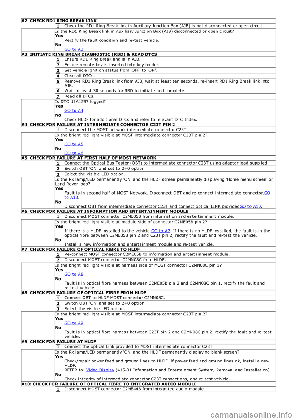
A2: CHECK RD1 RING BREAK LINK
Check the RD1 Ring Break link in Auxil iary Juncti on Box (AJB) is not dis connected or open circui t.
Is t he RD1 Ring Break li nk in Auxil iary Juncti on Box (AJB) dis connected or open circui t?YesRecti fy t he faul t condit ion and re-tes t vehi cl e.NoGO to A3.
A3: INIT IAT E RING BREAK DIAGNOST IC (RBD) & READ DT CSEns ure RD1 Ring Break l ink i s in AJB.
Ens ure remote key is i ns erted i nto key holder.
Set vehi cle i gni ti on s tat us from 'OFF' t o 'ON'.
Cl ear al l DTCs .
Remove RD1 Ri ng Break l ink from AJB, wai t at least t en s econds , re-ins ert RD1 Ri ng Break l ink int oAJB.
W ait at leas t 30 s econds for RBD to init iat e and complete.
Read all DTCs .
Is DTC U1A1587 logged?YesGO to A4.NoCheck HLDF for addit ional DTCs and refer t o rel evant DTC Index.
A4: CHECK FOR FAILURE AT INT ERMEDIAT E CONNECT O R C23T PIN 2
Di sconnect t he MOST net work i nt ermedi ate connect or C23T.
Is t he bright red li ght vi si ble at MOST intermediat e connector C23T pin 2?YesGO to A5.NoGO to A6.A5: CHECK FOR FAILURE AT FIRST HALF OF MOST NET WORK
Connect t he Opt ical Bus Tes ter (OBT) to intermediat e connector C23T usi ng adapt or lead s uppl ied.
Swi tch OBT 'ON' and s et t o 2+0 opt ion.
Select t he vi s ible LED opt ion.
Is t he Rx lamp/LED permanentl y 'ON' and t he HLDF s creen permanentl y dis playing 'Home menu s creen' orLand Rover l ogo?YesFault i s in second half of MOST Net work. Dis connect OBT and re-connect intermediat e connector.GOt o A13.NoDi sconnect OBT from i nt ermedi at e connect or C23T and connect opti cal LINK providedGO t o A10.
A6: CHECK FOR FAILURE AT INFORMAT ION AND ENT ERT AINMENT MODULE
Di sconnect MOST connect or C2ME05B from informat ion and ent ertai nment modul e.
Is t he bright red li ght vi si ble at module s ide of connector C2ME05B pin 2?YesIf there is a HLDF ins t al led t o t he vehi cle.GO to A7. If t here i s no HLDF ins t al led, t he fault i s in theopt ical fibre between C2ME05B pin 2 and C23T pin 2, rect ify t he fault and re-t es t the vehicle.NoInst all a new informat ion and entertai nment modul e and re-tes t vehi cle.
A7: CHECK FOR FAILURE OF OPT ICAL FIBRE T O HLDFRe-connect MO ST connect or C2ME05B to i nformati on and ent ert ainment module.
Di sconnect MOST connect or C2MN08C from HLDF.
Is t he bright red li ght vi si ble at harnes s s ide of MOST connect or C2MN08C pi n 1?YesGO to A8.NoFault i s in opt ical fi bre harnes s between C2ME05B pin 2 and C2MN08C pin 1, rect ify the faul t andre-t est vehicle.A8: CHECK FOR FAILURE OF OPT ICAL FIBRE FROM HLDF
Connect OBT to HLDF MOST connector C2MN08C.
Swi tch OBT 'ON' and s et t o 2+0 opt ion.
Select t he vi s ible LED opt ion.
Is t he bright red li ght vi si ble at MOST intermediat e connector C23T pin 2?YesGO to A9.NoFault i s in opt ical fi bre harnes s between C23T pi n 2 and C2MN08C pin 2, recti fy t he faul t and re-tes tvehicle.
A9: CHECK FOR FAILURE AT HLDFConnect t he opti cal Link provi ded to MOST int ermediat e connector C23T.
Is t he Rx lamp/LED permanentl y 'ON' and t he HLDF permanentl y dis playing bl ank s creen?YesCheck/repair power feed and ground lines t o HLDF. If power feed and ground lines ok, ins tal l a newHLDF.REFER t o: Vi deo Dis play (415-01 Informati on and Ent ert ainment Syst em, Removal and Inst all ati on).NoCheck int egrit y of int ermediat e connector C23T connecti ons , and re-t est vehicle.
A10: CHECK FOR FAILURE OF OPT ICAL FIBRE T O INT EGRAT ED AUDIO MODULEDi sconnect MOST connect or C2ME44B from int egrated audio module.
Page 1865 of 3229
1
1
1
1
1
1
1
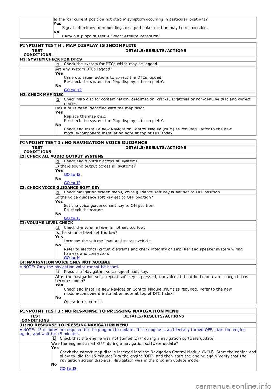
Is t he 'car current posi ti on not st able' sympt om occurri ng in part icul ar locat ions ?YesSi gnal reflecti ons from buil dings or a part icular locati on may be respons ible.NoCarry out pinpoint t est A "Poor Satell it e Recept ion"
PINPOINT TEST H : MAP DISPLAY IS INCOMPLETE
T ESTCONDIT IONSDET AILS/R ESULT S/ACT IONS
H1: SYST EM CHECK FOR DT CSCheck t he sys t em for DTCs whi ch may be l ogged.
Are any s yst em DTCs l ogged?YesCarry out repai r act ions t o correct t he DTCs logged.Re-check t he s ys t em for 'Map dis play i s i ncomplet e'.NoGO t o H2.H2: CHECK MAP DISC
Check map di sc for cont aminat ion, deformat ion, cracks , s cratches or non-genui ne dis c and correctmarket.Has a fault been i dent ified wi th the map dis c?YesReplace t he map di sc.Re-check t he s ys t em for 'Map dis play i s i ncomplet e'.NoCheck and ins t al l a new Navigat ion Control Modul e (NCM) as required. Refer t o t he newmodul e/component ins t al lat ion not e at top of DTC Index.
PINPOINT TEST I : NO NAVIGATION VOICE GUIDANCE
T ESTCONDIT IONSDET AILS/R ESULT S/ACT IONS
I1: CHECK ALL AUDIO OUT PUT SYST EMSCheck audi o output acros s all s yst ems .
Is t here s ound output across all s ys t ems ?YesGO t o I2.NoGO t o I3.
I2: CHECK VOICE GUIDANCE SO FT KEYCheck navi gat ion screen menu, voice guidance s oft key is not s et t o OFF posi ti on.
Is t he voice guidance soft key set t o OFF pos it ion?YesSet t he voice guidance soft key to O N posi ti on.Re-check t he s ys t emNoGO t o I3.I3: VOLUME LEVEL CHECK
Check t he vol ume l evel is not s et t oo low.
Is t he volume l evel s et too low?YesIncrease the vol ume level and re-tes t vehi cl e.NoRefer to el ect ri cal circui t diagrams and check int egrit y of ampli fier and s peaker s yst em wiringharnes s and connect ors .GO t o I4.
I4: NAVIGAT ION VOICE ONLY NOT AUDIBLE• NOTE: Onl y the navigat ion voice cannot be heard.
Press the 'Navi gat ion voi ce repeat ' s oft key.
After t he navi gat ion voi ce repeat soft key is pres s ed, can voice s t il l not be heard even t hough it hasbecome l ouder?YesCheck and ins t al l a new Navigat ion Control Modul e (NCM) as required. Refer t o t he newmodul e/component ins t al lat ion not e at top of DTC Index.NoO perati on is normal.
PINPOINT TEST J : NO RESPONSE TO PRESSING NAVIGATION MENU
T ESTCONDIT IONSDET AILS/RESULT S/ACT IONS
J1: NO RESPONSE T O PRESSING NAVIGAT ION MENU
• NOTE: 15 minutes are required for t he program t o update. If the engine i s acci dentally turned OFF, s tart the engi neagain, and wait for 15 minut es.
Check t hat t he engine was not t urned 'O FF' during a navi gat ion software updat e.
W as t he engi ne turned 'OFF' during a navigat ion s oft ware updat e?YesCheck t he correct map di sc is i ns erted i nto t he Navigati on Control Module (NCM). Start the engine andal low to idle for 15 mi nut es Turn t he engi ne 'OFF', and t hen s tart the engine again.Verify t hat t henavigat ion s creen dis plays . Navi gat ion was in the program update mode.NoGO t o J3.
Page 1870 of 3229
ClockAntenna powerLight Emit t ing Di ode (LED) il lumi nat ion.
In transi t mode t he CAN port and t he ON/OFF s wit ch are t he only ci rcuit s that are left act ive.
The CAN port is l eft open to allow the EXIT from transi t mode s ignal to be received. The O N/OFF s wit ch is left act ive t oall ow feedback to the driver vi a t he head uni t LCD (liqui d crys tal dis play), t hat the unit is i n t ransi t mode s houl d t he dri veratt empt t o power up the head unit . This wi ll only occur when t he vehicle engine is runni ng and the bat tery is above 12.3Volt s.
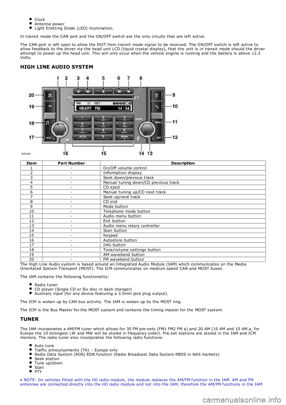
HIGH LINE AUDIO SYSTEM
ItemPart NumberDescription
1-On/O ff volume control2-Informat ion di spl ay
3-Seek down/previous t rack
4-Manual t uning down/CD previous t rack5-CD eject
6-Manual t uning up/CD next t rack
7-Seek up/next t rack8-CD s l ot
9-Mode butt on
10-Telephone mode but t on11-Audio menu but ton
12-Exit butt on
13-Audio menu rotary cont rol ler14-Scan but ton
15-Keypad
16-Autos tore butt on17-Info butt on
18-Tone/vol ume s ett ings but ton
19-AM waveband but t on20-FM waveband but ton
The High Li ne Audi o s yst em is bas ed around an Integrat ed Audio Module (IAM) which communicates on the Medi aOrientat ed Sys t em Trans port (MOST). The ICM communicat es on medium speed CAN and MOST buses .
The IAM cont ains t he fol lowi ng functi onali ty:
Radio t unerCD pl ayer (Si ngle CD or Si x dis c i n dash changer)Auxi li ary i nput (for any device feat uring a 3.5mm jack pl ug out put).
The ICM is woken up by CAN bus acti vi ty. The IAM i s woken up by the MOST ri ng.
The ICM is the Bus Mas t er for the MOST s ys t em and contai ns the t iming mas t er for the MOST s ys t em.
TUNER
The IAM incorporat es a AM/FM t uner whi ch al lows for 30 FM pre-s ets (FM1 FM2 FM a) and 20 AM (10 AM and 10 AM a, forEurope t he 10 s tronges t LW and MW wil l be st ored in frequency order). Pre-s et s tat ions are st ored i n t he IAM and ICMmemory. The radio t uner al so incorporat es the foll owi ng radi o functi ons :
Auto tuneTraffi c announcement s (TA) – Europe onlyRadio Dat a Syst em (RDS) EON funct ion (Radio Broadcast Dat a Sys tem RBDS in NAS markets)Seek st ati onTune up/downScanPTY
• NOTE: On vehicles fit t ed wit h t he HD radio module, t he module replaces the AM/FM funct ion i n t he IAM. AM and FMantennae are connect ed direct ly i nto the HD radio module and not int o t he IAM; therefore t he AM/FM functi ons in the IAM
Page 1885 of 3229
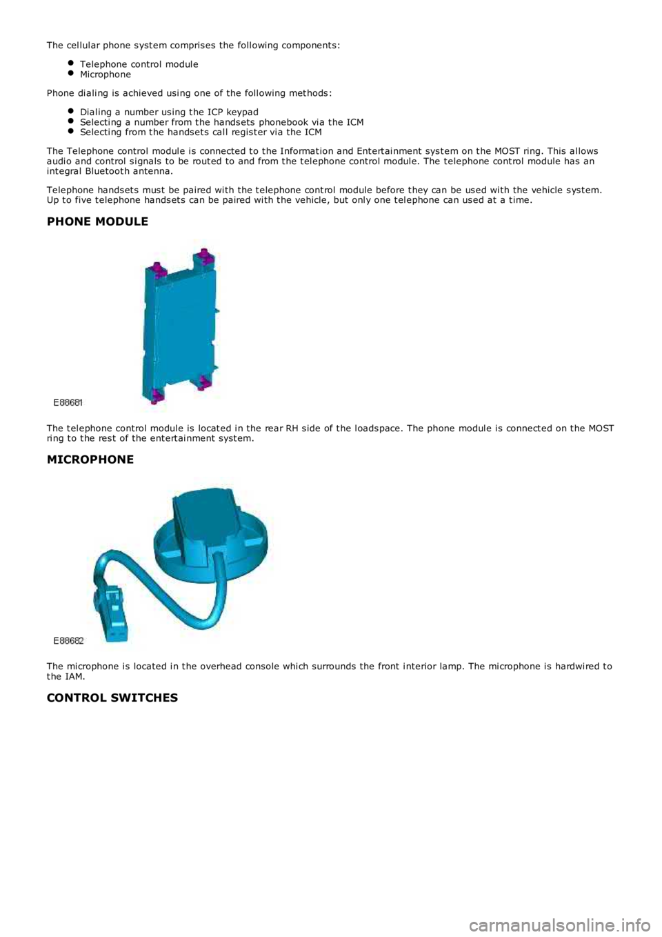
The cel lul ar phone s yst em compris es the foll owing component s:
Telephone control modul eMicrophone
Phone di ali ng is achieved usi ng one of the foll owing met hods :
Dial ing a number us ing t he ICP keypadSelecti ng a number from t he hands ets phonebook vi a t he ICMSelecti ng from t he hands et s cal l regis t er vi a the ICM
The Telephone control modul e i s connected t o t he Informat ion and Ent ert ai nment sys t em on t he MOST ring. This al lowsaudi o and control s i gnals to be rout ed to and from t he t el ephone control modul e. The t elephone cont rol module has anint egral Bluetoot h antenna.
Telephone hands et s mus t be paired wi th the t elephone cont rol module before t hey can be us ed wi th the vehicle s ys t em.Up t o five t elephone hands et s can be paired wi th t he vehicle, but onl y one t el ephone can us ed at a t ime.
PHONE MODULE
The t el ephone control modul e is locat ed i n the rear RH s ide of t he l oads pace. The phone modul e i s connect ed on t he MOSTri ng t o t he res t of the ent ert ai nment sys t em.
MICROPHONE
The mi crophone i s located i n t he overhead cons ole whi ch surrounds the front i nterior lamp. The mi crophone i s hardwi red t ot he IAM.
CONTROL SWITCHES
Page 1886 of 3229
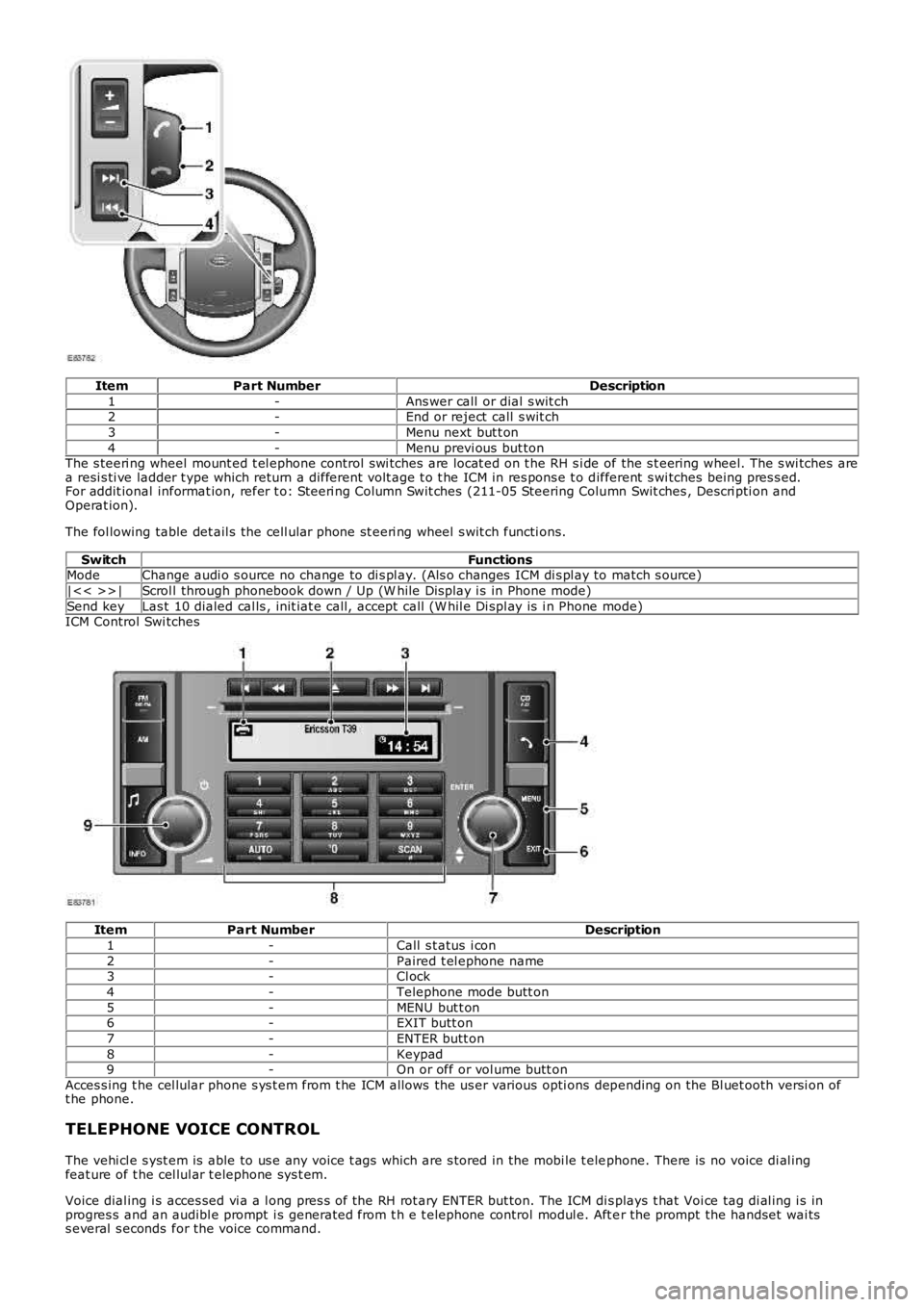
ItemPart NumberDescription
1-Ans wer call or dial s wit ch2-End or reject call s wit ch
3-Menu next but t on
4-Menu previ ous but tonThe s teeri ng wheel mount ed t el ephone control swi tches are locat ed on t he RH s i de of the s t eering wheel. The s wi tches area resi s ti ve ladder t ype which return a different volt age t o t he ICM in res pons e t o different s wi tches being pres s ed.For addit ional informat ion, refer t o: Steeri ng Column Swit ches (211-05 Steering Column Swit ches , Descri pti on andOperat ion).
The fol lowing table det ail s the cell ular phone st eeri ng wheel s wit ch functi ons.
SwitchFunctionsModeChange audi o s ource no change to di s pl ay. (Als o changes ICM di s pl ay to match s ource)
|<< >>|Scrol l through phonebook down / Up (W hile Dis play i s in Phone mode)
Send keyLas t 10 dialed cal ls , init iat e call, accept call (W hil e Di spl ay is i n Phone mode)ICM Control Swi tches
ItemPart NumberDescription
1-Call s t atus i con
2-Paired t el ephone name3-Cl ock
4-Telephone mode butt on
5-MENU but t on6-EXIT butt on
7-ENTER butt on
8-Keypad9-On or off or vol ume butt on
Acces s ing t he cel lular phone s ys t em from t he ICM allows the us er various opti ons depending on the Bl uet ooth versi on oft he phone.
TELEPHONE VOICE CONTROL
The vehi cl e s yst em is able to us e any voice t ags which are s tored in the mobi le t elephone. There is no voice di al ingfeat ure of t he cel lul ar t elephone sys t em.
Voice dial ing i s acces sed vi a a l ong pres s of the RH rot ary ENTER but ton. The ICM dis plays t hat Voi ce tag di al ing i s inprogres s and an audibl e prompt i s generated from t h e t elephone control modul e. Aft er the prompt the handset wai tss everal s econds for the voice command.
Page 1894 of 3229
PRINCIPLES OF OPERATION
The s ys t em us ed t o calcul ate the current pos it ion of t he vehicle i s called the Gl obal Pos it ioning Sys tem (GPS). The sys temuti li zes s at el li tes whi ch are owned by t he Unit ed St at es Depart ment of Defens e. A t otal of 24 s atel lit es orbi t the earthevery 12 hours at a hei ght of 20,000 km (12500 miles ), and bet ween 5 and 11 of t hese sat elli tes can be seen from as ingle poi nt at any gi ven ti me. The orbit s are ti lt ed to the earth's equat or by 55 degrees to ens ure coverage of polarregi ons . Each sat elli te transmit s radio si gnal s t o provide i nformati on about t he s atell it e's pos it ion, for example t helat it ude, l ongi tude, alt it ude, almanac data and an accurat e t ime s ignal generat ed by an on-board at omi c cl ock. Eachs atell it e cont ains four at omic cl ocks .
The vehi cl e needs to receive data from at l eas t four different sat elli tes t o gi ve a t hree dimens ional fi x on i ts currentposi ti on.
As t he vehi cl e moves , this informati on is cont inual ly bei ng updat ed. The computer determines whi ch sat ell it es are 'vi s ible't o the sys tem and t hei r current posi ti on and rel ati ons hip to each ot her. Usi ng t hi s i nformat ion t he computer can accountfor pos it ional deviat ions of t he sat ell it es and compens at e t o enhance t he accuracy of t he navi gati on sys t em.
The Global Pos i ti oni ng Sys t em (GPS) si gnal i s als o known as t he Precis ion Pos it ioning Si gnal (PPS).
PPS predict abl e accuracy i s:
22 met ers horizont al accuracy27.7 meters verti cal accuracy200 nanos econds t ime accuracy.
The navi gat ion sys tem receives GPS i nformat ion vi a t he GPS antenna. The GPS s ignal s are used by the navigati oncomput er to cal cul at e t he vehi cles posi ti on. Once t he driver has ent ered a des t ination, t he navi gati on comput er cancal cul ate a rout e, bas ed on t he dri ver's pre-determined preferences or the defaul t set ti ngs in the navigati on comput er.
The navi gat ion sys tem receives GPS (global pos it ioning sys tem) informati on via t he GPS ant enna. The GPS s ignals areus ed by the navigat ion computer t o cal cul ate the vehicles pos it ion. Once the driver has input a desi red des t inati on thenavi gat ion comput er can calculat e a rout e, bas ed on the drivers pre-determined preferences or the defaul t set ti ngs in thenavi gat ion comput er.
The navi gat ion sys tem is access ed by press i ng the navigat ion s oft key on t he t ouch screen dis play.
Navigati on is i nit iat ed by the driver enteri ng a des ti nat ion. This can be achieved by:
Entering i n an addres s usi ng t he touch s creen dis play.Entering a pos t code.Choos i ng a previous des ti nat ionChoos i ng a point of int eres t from t he map di sc dat abas e.Choos i ng the home locat ion.Choos i ng a memory s tored locati on.
The dri ver i s t hen gui ded to the des ti nat ion by a s croll ing map di s pl ay and voi ce guidance. The dis play can be vari ed bys cal e and dis play t ype.
In addi ti on t o the navigat ion s ys tem there are t wo market dependant s ys tems that s uppl y ext ra informat ion t o t henavi gat ion sys tem and t he dri ver. Thes e are:
Traffi c Mess age Channel (TMC) – Europe only.Vehicle Informati on and Communicati on Sys t em (VICS) - Japan onl y.
Traffic Message Channel (TMC)
The Traffi c Mess age Channel (TMC) traffic data is currentl y broadcas t in many European countries .
TMC i s a funct ion of t he FM (frequency modulati on) Radi o Data Sys t em (RDS). The s ystem broadcas ts real-ti me t raffi c andweather informat ion. TMC i nformat ion i s received via the normal FM radi o antenna.
Data mes sages are received and decoded by t he TMC receiver and pass ed ont o t he navi gat ion s ys tem, whi ch then deli verst hem via t he navigati on s ys t em i nterface. TMC mess ages can be fi lt ered by t he navigati on comput er so that only t hoserel evant t o t he current journey are dis played, allowi ng the navigat ion s ys tem to offer dynamic route gui dance - alerti ng thedri ver of a probl em on the pl anned rout e and calculat ing an al ternat ive rout e t o avoid t he i nci dent . All TMC event s on t hemap can be vi ewed not just the ones on t he cal cul ated route.
TMC t raffi c informat ion s yst ems conform t o a gl obal s tandard that has been adopt ed by:
t raffic dat a gatherers ,informat ion s ervi ce provi ders ,broadcas t ers , andvehi cl e/recei ver manufacturers .
All TMC recei vers us e t he s ame li s t of event codes , while the locat ion dat abas e (on t he map dis c) cont ains both a count ry-s pecific set of locati on codes for the s t rat egi c European road net work.
Vehicle Information and Communication System (VICS)
The Vehicle Informati on and Communicati on Sys t em (VICS) i s broadcas t i n the Japanes e market.
The VICS sys t em s uppl ies t he navi gati on comput er wit h informat ion t hat enables t he computer t o inform the vehicle dri verof traffic condi ti ons in the vehicle's vi ci nit y and cal cul ate an alt ernati ve route if neces s ary. Informat ion i s t rans mit ted tot he navi gat ion s ys tem through three routes :
1. Radi o Frequency Transmis si on
Page 1934 of 3229
Publi s hed: 11-May-2011
Exterior Lighting - Headlamp Adjustment
General Procedures
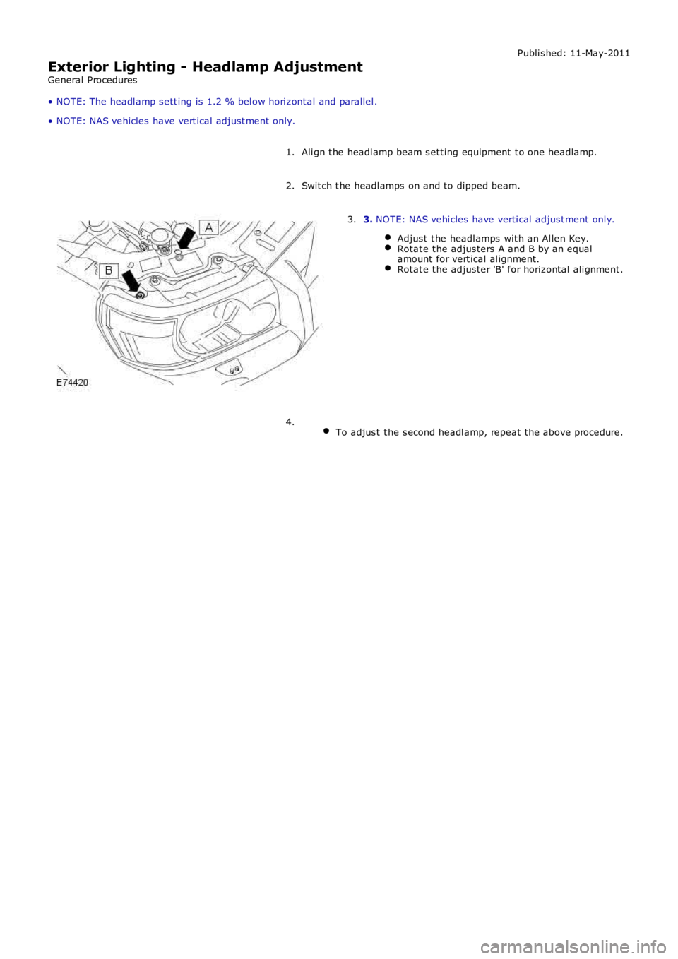
• NOTE: The headl amp s ett ing is 1.2 % bel ow hori zont al and parallel .
• NOTE: NAS vehicles have vert ical adjust ment only.
Ali gn t he headl amp beam s ett ing equipment t o one headlamp.1.
Swit ch t he headl amps on and to dipped beam.2.
3. NOTE: NAS vehi cles have verti cal adjus t ment onl y.
Adjus t t he headl amps wit h an Al len Key.Rotat e t he adjus ters A and B by an equalamount for vert ical al ignment.Rotat e t he adjus ter 'B' for horizontal ali gnment .
3.
To adjus t t he s econd headl amp, repeat the above procedure.4.